 Zhimin Li
 Zibin Lin1*
 Longsheng Zeng
 Xue-Feng Zhu
95% of researchers rate our articles as excellent or good
Learn more about the work of our research integrity team to safeguard the quality of each article we publish.
Find out more
ORIGINAL RESEARCH article
Front. Phys. , 29 June 2022
Sec. Physical Acoustics and Ultrasonics
Volume 10 - 2022 | https://doi.org/10.3389/fphy.2022.922010
This article is part of the Research Topic Advances in Phononic and Acoustic Metamaterials View all 7 articles
Manipulating underwater acoustic waves along the prescribed trajectory has great potential for various applications. Traditional metasurfaces for underwater acoustic modulation usually have complex structural designs and are complicated to manufacture. Here, we propose a simple strategy of embedding air bubbles of different sizes inside the polymer to freely manipulate the transmitted underwater acoustic wavefields. The transmitted phase shift covers the entire
As a kind of artificial microstructure material, metamaterial has exotic physical properties that are not seen in traditional materials, such as negative refractive index [1] and negative density [2]. Conventional metamaterials are usually limited by bulky structures and complicated manufacturing processes. To modulate waves in 2D scales, the concept of metasurfaces was proposed in optics [3] based on the generalized Snell’s law (GSL) [4]. With the advantage of ultrathin and lightweight compact structure, the acoustic metasurface has also attracted broad attention in the past decade [5–10]. By intriguingly designing the functional units, multiple functionalities can be realized, such as abnormal reflection [11, 12], negative refraction [13, 14], beam focusing [15], vortex sources and perfect absorption [16–19], and self-bending beams [20]. Li et al. [21] proposed the ultrathin planar acoustic metasurfaces with the phase shifts spanning over a full
In this article, we propose the bubble-arrayed acoustic metasurface (BAAM) by introducing air holes into the functional unit to manipulate the transmitted wave. First, a perforated unit cell with an air bubble inside a square structure was constructed. Second, we designed a bubble array functional unit composed of nine air bubbles with a diameter D. By changing the diameter D, the phase shift of
When an acoustic wave with an incident angle
where
We consider a perforated unit cell composed of an air hole (the diameter being D) inside a square polymer (the width being a), as shown in Figure 1A. Figures 1B and C present the functional unit with nine periodically arrayed unit cells and BAAM, respectively. The blue medium indicates the water, and the gray and white medium are polymer and water. By arranging the functional unit with different diameters D, the metasurface can be constructed to steer the transmitted wave field. The material properties and geometric parameters of the BAAM are listed in Tables 1 and 2, respectively. In this article, the full-wave simulations are performed using commercial finite element software COMSOL Multiphysics with a preset Pressure Acoustic and Solid Mechanics module. Figure 2A illustrates the strip model with a functional unit. Continuous periodic boundary conditions are applied on the two sides of the strip model to simulate a periodically arranged structure. Perfectly matched layers (PMLs) are adopted at the upper end to absorb the reflection from the boundaries. The normally incident plane wave is employed at the bottom end of the strip model. To evaluate the phase shift and the transmission ratio, we set a probe line in the near area of the upper end, as shown in Figure 2A. The detected transmission ratio is defined as:
where
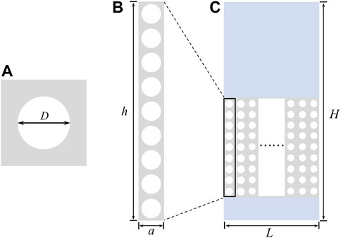
FIGURE 1. (A) The square unit cell with perforated air holes; (B) the functional unit with nine square units; and (C) the schematic diagrams of the bubble-arrayed metasurface.
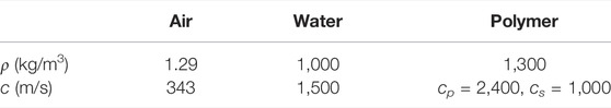
TABLE 1. Material properties.

TABLE 2. Geometric parameters (unit: mm).
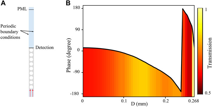
FIGURE 2. (A) The schematic diagrams of the functional model and (B) simulated phase shift and transmission ratio varying with the diameter D at f = 700 kHz.
From the GSL, we can conclude that the phase gradient plays a significant role in the wavefield manipulation. Thus, based on the relationship between the continuous phase shift and the diameter D, multiple functionalities of the proposed BAAM can be achieved, such as anomalous refraction and self-bending beams.
Assuming that the acoustic wave is normally incident on the designed structure, Eq. 3 can be rewritten as:
From Eq. 6, we can conclude that the transmitted angle varies with the phase shift, which indicates it is likely to steer the transmitted wave propagating along the direction as we want. Once we know the required phase shift and obtain the corresponding diameter D, the abnormal refraction will be achievable. This section performs the anomalous refraction effects of the proposed BAAM. Without loss of generality, we select three phase gradients:
FIGURE 3. (A–C) The relationship between phase shift and air hole diameter D with phase gradient of π/6, 2π/15, and π/9. (D–F) The corresponding transmitted wavefields of abnormal refraction with the refracted angles of 20.9°, 16.6°, and 13.8°, respectively.
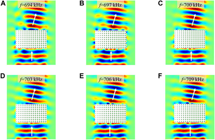
FIGURE 4. (A–F) Simulated pressure field of abnormal refraction with a phase shift
In order to further verify the feasibility of the proposed metasurface to manipulate the acoustic wave, two different cases of self-bending beam propagation trajectories will be presented: the Bezier beam and the bottle beam.
In this section, we use a third-order Bezier curve to designate the acoustic propagation path of the transmitted wavefield. The Bezier curve is a polynomial function concerning the parameter t, which is expressed as:
where P(t) is the specific expression of a Bezier curve and n = 3 is the order. It can be found that once a series of points from
Figure 5A illustrates the process of obtaining the phase profile in the y-direction. By substituting different parameter t into Eq. 8, we obtain the designed trajectory (red curve) owning the shape of the Bezier curve with
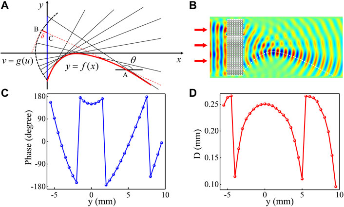
FIGURE 5. Self-bending beams for the Bezier curve trajectory at the frequency of 700 kHz. (A) Schematic illustrations of the self-bending beam; (B) numerically simulated sound pressure field of the Bezier beam; and (C–D) the theoretical phase shifts and the corresponding diameter D along the y-direction.
We present the tangential ray (red dash line) as an example, it intersects with the trajectory, wavefront, and y-axis at point
Since the acoustic rays are perpendicular to the wavefront, the relationship between the slope of points A and B can be expressed as:
By simplifying Eq. 11, we can obtain:
where
Combining Eqs 8–12, the relationship between the phase shift profile and the transmitted angle can be written as:
It can be found from Eq. 14 that once the desired beam path is determined, the phase shift to design the BAAM will be readily constructed. We use 31 functional units to build the BAAM to realize the Bezier beam effect. The simulated result of the acoustic pressure is provided in Figure 5B. The white dashed line represents the theoretical trajectory of the Bezier beam effect. It is easy to find that the simulated result is in good agreement with the theoretical value. Similar to the abnormal refracted, Figure 5C illustrates the desired phase distribution of 31 units obtained by Eq. 14. According to the relationship between the phase shift and the diameter D, the diameter D can be selected to design the BAAM consisting of 31 functional units. The distribution of the diameter D along the y-direction is shown in Figure 5D.
When the trajectory of the self-accelerating beam is a bottle trajectory, the transmitted acoustic wave propagates along a circular path, which is defined by:
where
where
Figure 6 (A) illustrates the schematic diagram of the circular trajectory described by
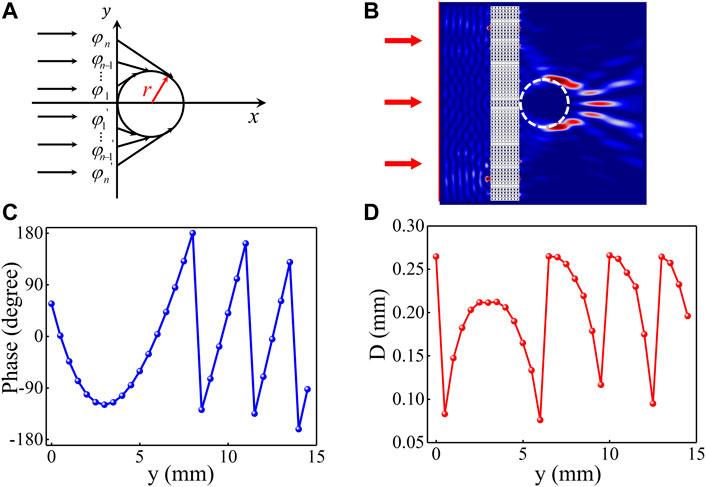
FIGURE 6. Self-bending beams for the acoustic bottle beam at f = 700 kHz. (A) Schematic illustrations of the acoustic bottom beam; (B) numerically simulated sound intensity field of the acoustic bottom beam; and (C–D) the theoretical phase shifts and the corresponding diameter D along the y-direction.
In summary, we numerically demonstrated a bubble-arrayed acoustic metasurface to manipulate the transmitted wave field by changing the diameter D of the air bubbles. The abnormal refraction, Bezier beams, and the acoustic bottle beam can be realized with the proposed metasurface, and the simulated results show good agreement with the theoretical predictions. The special feature of the BAAM is that air bubbles are introduced into the metasurface, which provides a unique design method to simplify the configurations with a relatively high transmission ratio. With the advantage of wavefield modulation of the transmitted wave over broadband frequencies, the compact and straightforward design of the proposed BAAM without complex manufacturing opens a new avenue for potential underwater applications in acoustic wave engineering manipulation and ultrasound imaging.
The raw data supporting the conclusions of this article will be made available by the authors, without undue reservation.
ZML: software, data curation, and writing—original draft. LSZ and HW: software and validation. ZBL and XFZ: supervised the study, funding acquisition, and writing—review and editing.
This work was supported by the National Key R&D Program of China (Grant Nos. 2020YFA0211400 and 2020YFA0211401).
The authors declare that the research was conducted in the absence of any commercial or financial relationships that could be construed as a potential conflict of interest.
All claims expressed in this article are solely those of the authors and do not necessarily represent those of their affiliated organizations, or those of the publisher, the editors, and the reviewers. Any product that may be evaluated in this article, or claim that may be made by its manufacturer, is not guaranteed or endorsed by the publisher.
1. Wen J, Shen H, Yu D, Wen X. Exploration of Amphoteric and Negative Refraction Imaging of Acoustic Sources via Active Metamaterials. Phys Lett A (2013) 377:2199–206. doi:10.1016/j.physleta.2013.06.016
2. Li J, Chan CT. Double-negative Acoustic Metamaterial. Phys Rev E Stat Nonlin Soft Matter Phys (2004) 70:055602. doi:10.1103/PhysRevE.70.055602
3. Yu N, Capasso F. Flat Optics with Designer Metasurfaces. Nat Mater (2014) 13:139–50. doi:10.1038/nmat3839
4. Yu N, Genevet P, Kats MA, Aieta F, Tetienne J-P, Capasso F, et al. Light Propagation with Phase Discontinuities: Generalized Laws of Reflection and Refraction. Science (2011) 334:333–7. doi:10.1126/science.1210713
5. Assouar B, Liang B, Wu Y, Li Y, Cheng J-C, Jing Y. Acoustic Metasurfaces. Nat Rev Mater (2018) 3:460–72. doi:10.1038/s41578-018-0061-4
6. Jia D, Wang Y, Ge Y, Yuan S-Q, Sun H-X. Tunable Topological Refractions in Valley Sonic Crystals with Triple Valley Hall Phase Transitions. Prog Electromagnetics Res (2021) 172. 13–22. doi:10.2528/pier21102002
7. Tsang L, Liao T-H, Tan S. Calculations of Bands and Band Field Solutions in Topological Acoustics Using the Broadband Green's Function-KKR-Multiple Scattering Method. Pier (2021) 171:137–58. doi:10.2528/pier21081706
8. Tang S, Ren B, Feng Y, Song J, Jiang Y. The Generation of Acoustic Airy Beam with Selective Band Based on Binary Metasurfaces: Customized on Demand. Appl Phys Lett (2021) 119:071907. doi:10.1063/5.0060032
9. Lin Z, Xu W, Xuan C, Qi W, Wang W. Modular Elastic Metasurfaces with Mass Oscillators for Transmitted Flexural Wave Manipulation. J Phys D: Appl Phys (2021) 54:255303. doi:10.1088/1361-6463/abee47
10. Zeng L-S, Shen Y-X, Fang X-S, Li Y, Zhu X-F. Experimental Realization of Ultrasonic Retroreflection Tweezing via Metagratings. Ultrasonics (2021) 117:106548. doi:10.1016/j.ultras.2021.106548
11. Li Y, Jiang X, Li R-q, Liang B, Zou X-y, Yin L-l, et al. Experimental Realization of Full Control of Reflected Waves with Subwavelength Acoustic Metasurfaces. Phys Rev Appl (2014) 2:064002. doi:10.1103/physrevapplied.2.064002
12. Chen H. Anomalous Reflection of Acoustic Waves in Air with Metasurfaces at Low Frequency. Adv Condensed Matter Phys (2018) 2018:1–7. doi:10.1155/2018/5452071
13. Mei J, Wu Y. Controllable Transmission and Total Reflection through an Impedance-Matched Acoustic Metasurface. New J Phys (2014) 16:123007. doi:10.1088/1367-2630/16/12/123007
14. Zhu H, Semperlotti F. Anomalous Refraction of Acoustic Guided Waves in Solids with Geometrically Tapered Metasurfaces. Phys Rev Lett (2016) 117:034302. doi:10.1103/PhysRevLett.117.034302
15. Tang K, Qiu C, Lu J, Ke M, Liu Z. Focusing and Directional Beaming Effects of Airborne Sound through a Planar Lens with Zigzag Slits. J Appl Phys (2015) 117:024503. doi:10.1063/1.4905910
16. Mei J, Ma G, Yang M, Yang Z, Wen W, Sheng P. Dark Acoustic Metamaterials as Super Absorbers for Low-Frequency Sound. Nat Commun (2012) 3:756–7. doi:10.1038/ncomms1758
17. Ye L, Qiu C, Lu J, Tang K, Jia H, Ke M, et al. Making Sound Vortices by Metasurfaces. Aip Adv (2016) 6:085007. doi:10.1063/1.4961062
18. Li Z, Liu W, Li Z, Tang C, Cheng H, Li J, et al. Tripling the Capacity of Optical Vortices by Nonlinear Metasurface. Laser Photon Rev (2018) 12:1800164. doi:10.1002/lpor.201800164
19. Fan S-W, Wang Y-F, Cao L, Zhu Y, Chen A-L, Vincent B, et al. Acoustic Vortices with High-Order Orbital Angular Momentum by a Continuously Tunable Metasurface. Appl Phys Lett (2020) 116:163504. doi:10.1063/5.0007351
20. Li X-S, Zhou H-T, Wang Y-F, Wang Y-S. Modulation of Acoustic Self-Accelerating Beams with Tunable Curved Metasurfaces. Appl Phys Lett (2021) 118:023503. doi:10.1063/5.0035286
21. Li Y, Liang B, Gu Z-m., Zou X-y., Cheng J-c. Reflected Wavefront Manipulation Based on Ultrathin Planar Acoustic Metasurfaces. Sci Rep (2013) 3:2546. doi:10.1038/srep02546
22. Xie Y, Wang W, Chen H, Konneker A, Popa BI, Cummer SA. Wavefront Modulation and Subwavelength Diffractive Acoustics with an Acoustic Metasurface. Nat Commun (2014) 5:5553–5. doi:10.1038/ncomms6553
23. Zhu X, Li K, Zhang P, Zhu J, Zhang J, Tian C, et al. Implementation of Dispersion-free Slow Acoustic Wave Propagation and Phase Engineering with Helical-Structured Metamaterials. Nat Commun (2016) 7:11731. doi:10.1038/ncomms11731
24. Zhang P, Li T, Zhu J, Zhu X, Yang S, Wang Y, et al. Generation of Acoustic Self-Bending and Bottle Beams by Phase Engineering. Nat Commun (2014) 5:4316. doi:10.1038/ncomms5316
25. Li Z, Yang S, Wang D, Shan H, Chen D, Fei C, et al. Focus of Ultrasonic Underwater Sound with 3D Printed Phononic crystal. Appl Phys Lett (2021) 119:073501. doi:10.1063/5.0058415
Keywords: underwater metasurface, acoustic wave, abnormal refraction, self-bending beams, Bezier beam
Citation: Li Z, Lin Z, Zeng L, Wu H and Zhu X-F (2022) Underwater Transmitted Wavefront Manipulation Based on Bubble-Arrayed Acoustic Metasurfaces. Front. Phys. 10:922010. doi: 10.3389/fphy.2022.922010
Received: 17 April 2022; Accepted: 16 May 2022;
Published: 29 June 2022.
Edited by:
Ying Li, Zhejiang University, ChinaCopyright © 2022 Li, Lin, Zeng, Wu and Zhu. This is an open-access article distributed under the terms of the Creative Commons Attribution License (CC BY). The use, distribution or reproduction in other forums is permitted, provided the original author(s) and the copyright owner(s) are credited and that the original publication in this journal is cited, in accordance with accepted academic practice. No use, distribution or reproduction is permitted which does not comply with these terms.
*Correspondence: Zibin Lin, bGluemliaW4uZWR1QGdtYWlsLmNvbQ==; Xue-Feng Zhu, eGZ6aHVAaHVzdC5lZHUuY24=
Disclaimer: All claims expressed in this article are solely those of the authors and do not necessarily represent those of their affiliated organizations, or those of the publisher, the editors and the reviewers. Any product that may be evaluated in this article or claim that may be made by its manufacturer is not guaranteed or endorsed by the publisher.
Research integrity at Frontiers
Learn more about the work of our research integrity team to safeguard the quality of each article we publish.