- Air and Missile Defense College, Air Force Engineering University, Xi’an, China
In this article, we combine the frequency diverse array (FDA) with the vortex electromagnetic wave theory and propose a beamforming method in the generation of range-time-dependent orbital angular momentum (OAM) based on the circular FDA (CFDA). First, we establish a CFDA-based OAM-generating structure, based on which the feasibility of CFDA to generate OAM is verified. Then, we analyze the range-time-dependent characteristics of the generated OAM. Furthermore, concerning the field of radar imaging and target detection, we investigate beamforming with the CFDA-based OAM. Two main issues are addressed: beam collimation and sidelobe suppression. Therefore, according to the derived angular offset between the mainlobe direction and the beam axis, we steer the beam at the target through the phase shifter. Moreover, the sidelobe is suppressed by selecting an appropriate antenna pattern. Finally, based on the analysis of beam collimation and sidelobe suppression, we establish the CFDA configuration for beamforming. Numerical examples and simulations show the superiority of the proposed beamforming method.
1 Introduction
Radar, an electronic device for detecting targets using electromagnetic waves, is widely used in military and civil fields [1]. After a long period of development, phased array radar (PAR), owing to its high-flexible and high-gain beam, has become the central radar system at present [2]; [3]. However, although PAR has been widely used in multitarget detection, imaging, target tracking, and interference suppression, it is still restricted by its limited controllable degrees of freedom (DoFs). Therefore, for further development, it is urgent to seek innovations in radar technology to expand the DoFs of radar.
The frequency diverse array (FDA) seems to be a feasible array that means to expand the DoF of the radar beam owing to its range-time-dependent beampattern [4]. Antonik first proposed FDA in 2006 [5], and since then, it has attracted considerable attention on the radar [6]. Unlike a phased array (PA), an FDA introduces frequency offsets far smaller than the carrier frequency between each array element and thus produces an S-shaped beam [7]. The range-dependent beampattern of FDA expands the DoF of radar beam in the range domain. However, the S-shaped beam demonstrates the range and angle-coupling problem for the beampattern [8]. Therefore, in recent years, the dot-shaped beamforming was investigated to decouple the beampattern. Furthermore, the current methods for dot-shaped beamforming include nonlinear frequency offset design and subaperture structure application. First, several functions were applied to design the nonlinear frequency offsets, such as logarithmic function [9], sine function [10], square function [11], cubic function [11], hyperbolic tangent function [12], Hamming window function [13], Tayler window function [14], and Costas coding [15]. In addition, [16]and [17] used a genetic algorithm (GA) and a particle swarm optimization (PSO) algorithm to design the frequency offsets, respectively. Moreover, the subaperture structure was applied to decouple the beampattern [18]; [19]; [20]. However, the beampattern is also time-varying due to the introduced frequency offsets. Therefore, to solve the time-varying problem with the beampattern of the FDA, the time-modulation frequency offsets were proposed [21]; [22]; [23]. Moreover, the filter for time modulation at the transmitter was proposed to suppress the time-varying beampattern in [17]. However, up to now, the time-independent beampattern is not achieved in practice [24]. Once solving the range-angle-coupling and time-varying beampattern, FDA demonstrates a high application prospect in joint range-angle estimation [4], imaging [25]; [26], mainlobe jamming suppression [27]; [28], and deceive jamming signal generation [29].
The vortex electromagnetic (EM) wave is also feasible to expand the DoF of the radar beam owing to the carrying orbital angular momentum (OAM) [30]. The study of vortex waves began early in the field of optics. In 1992, Allen et al. discovered that a laser with Laguerre–Gaussian (LG) amplitude distribution carries OAM and its phase distribution is spatial helical [31]. The OAM with adjustable modes enables the optical vortex to modulate and transmit information [32]. After that, many mature results have been obtained in vortex optical communication. From a physical point of view, light can also be considered an EM wave, and thus the study of vortex EM in microwave bands has also been concerned. The vortex EM wave was studied in communication [33] and radar [34] in recent years. The vortex EM demonstrates its application perspectives for imaging and detection in radar. [35] found that when the radiation field of the vortex EM wave irradiates the target, the echo signal received by the radar contains the azimuth information of the target. Therefore, when using vortex EM waves for radar imaging, the azimuth information of the target can be obtained from the echo signal through signal processing. In recent years, various radar imaging models using OAM have been proposed [36–38], and the corresponding radar imaging algorithms [39,40]; [41] have been proposed to achieve one-dimensional and two-dimensional imaging models. In theory, the rotating Doppler effect can be produced when the vortex EM wave is irradiated on a rotating object. Therefore, the vortex EM wave radar can detect both the target’s radial and angular motion. Furthermore, several studies have investigated target detection based on vortex EM waves [42]; [43].
The uniform circular array (UCA) can be applied to the generation of OAM owing to its high controllable and good beamforming ability [34]. The UCA generates OAM with multiple modes by shifting the proper phases of the array elements. Moreover, the FDA can also achieve phase shifts by changing the frequency offsets. Thus, the circular FDA (CFDA) has the potential to produce OAM. In addition, due to the introduction of frequency offset, the generated OAM may be range-time-dependent. Therefore, in the background of radar imaging and target detection, combining the FDA structure with the vortex EM wave concept, we propose a beamforming method to generate range-dependent OAM based on CFDA. Our main contributions are summarized as follows:
1) We establish an OAM-generating structure based on CFDA. Then, based on the proposed structure, we verify the feasibility of CFDA to generate OAM. Furthermore, the characteristics of the generated OAM are investigated by analyzing the periodicity and OAM spectrum.
2) The beamforming method for the CFDA-based OAM is proposed. The proposed beamforming method concerns the following two issues: beam collimation and sidelobe suppression. To achieve beam collimation, we derive the rotation angle of the beam axis and thus steer the signal at the target through the phase shifter. Furthermore, an appropriate antenna pattern is selected to suppress the sidelobe.
3) The CFDA configuration for beamforming is established. Based on the analysis of time modulation, beam collimation, and sidelobe suppression, the configuration of CFDA for beamforming is proposed.
The remainder of the article is organized as follows: Section 2 formulates the OAM-generating structure based on CFDA and analyzes the characteristics of the generated OAM. Section 3 proposes the beamforming for the CFDA-based OAM considering time modulation, beam collimation, and sidelobe suppression. Furthermore, the numerical simulation results are presented in Section 4. Finally, Section 5 draws conclusions.
2 Orbital Angular Momentum-Generating Structure Based on Circular FDA
2.1 Signal Model
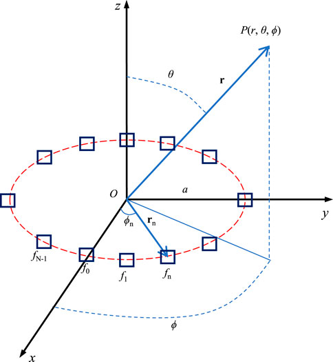
Figure 1 illustrates the N-antenna CFDA with radius a in the XOY plane. Generally, the directional array antennas are considered with uniform distribution. Hence, setting antenna 0 on the x-axis, antenna n is at azimuth
where f0 is the reference basic frequency, Δf denotes the tiny frequency offset satisfying Δf ≪ f0, and c is the speed of light.
For an arbitrary point
where
Under the equal-amplitude and equal-phase excitation assumption, we have an = a0 and φn = φ0. Moreover, the directional pattern is assumed to be stable, that is, fx3. Then, Eq. 3 can be rewritten as
In the far-field, we approximate the amplitude with |r − rn| ≈ r, and the phase with
with
Then, the equivalent electric field in the far-field can be approximately given by
where
Actually,
Thus, Eq. 8 can be further rewritten as
where the array factor AFFDA can be given by
When there are enough array antennas, the summation in the array factor AFFDA can be replaced by an integral, then Eq. 12 can be rewritten as
Let ψ′ = ϕ − ψ, while
where
In summary, the equivalent electric field produced by CFDA at
Equations 12 and 16 indicate that the CFDA can generate vortex EM waves owing to its vortex phase factor
2.2 Characteristics of the Generated Orbital Angular Momentum
From Eq. 10, the generated OAM modes can be further rewritten as
Furthermore, we have the following two remarks for the mode of the generated OAM:
1) The OAM mode generated by CFDA are range-time-dependent, and OAM mode is continuous with range and time. Then, we can learn that there are non-integer modes during the transmission of the generated vortex EM waves.
2) The vortex EM wave generated by the array is a discrete phase sampling. Thus, according to the Nyquist sampling theorem, we learn that the OAM mode does not increase indefinitely and is limited by the number of elements:
Therefore, considering the OAM mode period relative to range, we have
Thus,
Similarly, considering the OAM mode period relative to time, we have
Thus,
In addition, the OAM spectrum can be derived according to the Fourier transform relationship between the OAM distribution Al and azimuth phase
3 Beamforming for the Circular FDA-Based Orbital Angular Momentum
For CFDA radar, the quality of imaging and detection is closely related to the energy distribution, phase distribution, and OAM purity of the vortex EM wave. However, there are several problems with the CFDA-based OAM to address, such as the hollow beampattern, the mainlobe pointing changing with the OAM mode, and the high sidelobe energy. These problems bring some challenges to the application of OAM in radar. Therefore, concerning beam collimation and sidelobe suppression, we proposed a beamforming method for the CFDA-based OAM.
3.1 Beam Collimation
Unlike the traditional plane wave, the vortex EM wave has a hollow energy distribution and OAM mode-varying mainlobe direction. Therefore, turning to the application of OAM in radar detection and imaging, the beam collimation for the vortex EM wave should be considered.
For the CFDA, beamforming is a feasible method for beam collimation. In addition, considering the energy attenuation of the OAM with non-integer mode, we generally set the CFDA-generated OAM as the integer mode at the target point. Therefore, for the OAM with integer mode, the mainlobe direction θ0 can be derived based on the Bessel function by
Thus, at time t, we apply the phase shifter to steer the signal at the target with position
Then, the array factor after beam collimation (at time t) can be given by
For the simple expression, we set ɛ = k0a sin θ and
Comparing Eqs. 14 and 27, we can see that the integral term in Eq. 30 cannot be rewritten as the Bessel function due to the introduction of the steering vector. To further analyze the array factor after beam collimation, we introduce the Jacohi–Anger expansion given by
Then, Eq. 27 can be rewritten as
From Eq. 29, we can see that the generated OAM modes after beam collimation are a mixture of several integer modes. Moreover, the mode weights can be approximated by the term
3.2 Sidelobe Suppression
As we know, the beam of the vortex EM wave is annular around the direction axis with a higher sidelobe. The higher sidelobes cause a severe waste of emission energy. Therefore, sidelobe suppression must be considered in practical applications.
According to the radar radiation theory, an appropriate antenna pattern can effectively suppress the sidelobes. Therefore, in the article, we consider three typical antenna patterns as follows:
3.3 Circular FDA Configuration for Beamforming
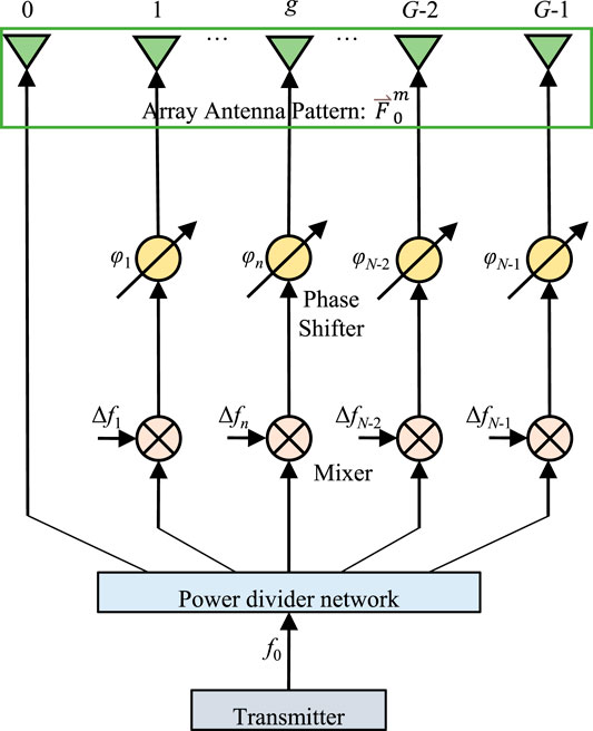
After time modulation, beam collimation, and sidelobe suppression, the equivalent electric field generated by CFDA can be given by
Therefore, based on the analysis of time modulation, beam collimation, and sidelobe suppression, the configuration of CFDA for beamforming is shown in Figure 2.
4 Simulation Results
In this section, several simulations are conducted to verify effectiveness of the proposed OAM beamforming based on the CFDA. Unless stated otherwise, the simulation parameters are set at: f0 = 20GHz, Δf = 10MHz,
4.1 Model Verification
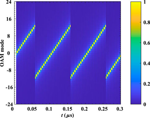
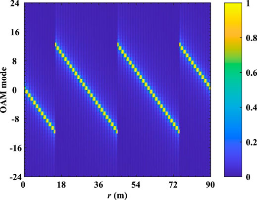
In the first example, the radiation characteristics of the generated OAM based on CFDA are demonstrated. The observation plane is set perpendicular to the beam axis (z-axis). Setting the observation distance at z = 60/N = 2.5m, Figure 3 shows the beam distribution and phase distribution of the CFDA-based OAM at different times. It can be seen that the mode of the CFDA-based OAM transfers with time varies. At certain times, the generated OAM shows integer modes. However, non-integer modes occur during the transmission. To further analyze the time-dependent characteristic and according to Eqs. 22 and 23, Figure 4 gives the CFDA-based OAM spectrum with time while r = 2.5m. We can see that at the fixed range, the mode of the CFDA-based OAM increases periodically with time, and the period is 0.1 µs
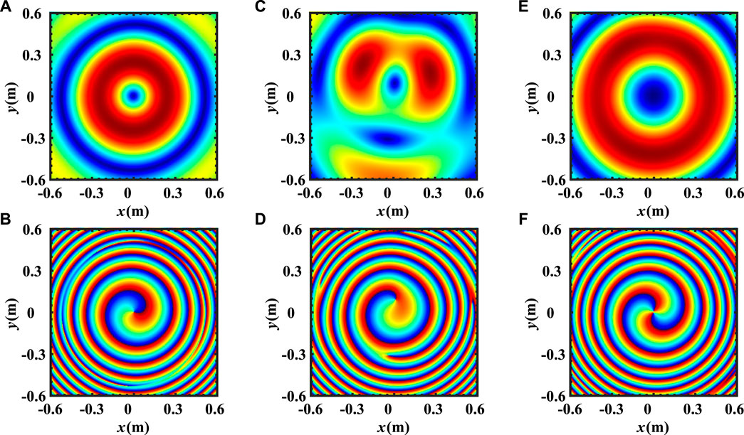
FIGURE 3. Beam distribution and phase distribution of the CFDA-based OAM at different times while z = 2.5m. (A) Beam distribution while t = 12.5ns; (B) phase distribution while t = 12.5ns; (C) beam distribution while t = 14.583ns; (D) phase distribution while t = 14.583ns; (E) beam distribution while t = 16.667ns; and (F) phase distribution while t = 16.667ns.
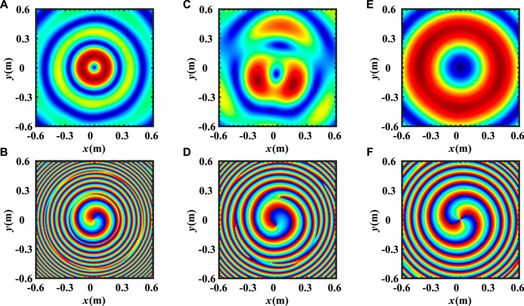
FIGURE 5. Beam distribution and phase distribution of the CFDA-based OAM at observation distances while t = 0.3 μs. (A) Beam distribution while z = 1.25m; (B) phase distribution while z = 1.25m; (C) beam distribution while z = 1.875m; (D) phase distribution while z = 1.875m; (E) beam distribution while z = 2.5m; (F) phase distribution while z = 2.5m.
4.2 Analysis of Beam Collimation
In this example, we analyze the effect of the beam collimation proposed in Section 3.1. It is remarked that the simulations are at fixed time t = 0.3 μs. Figure 7 compares the beampattern before and after beam collimation in the pitch dimension for the targets at

FIGURE 7. Phase distribution of the observation plane perpendicular to the Z-axis and the beam axis after beam collimation. (A) Observation plane perpendicular to the Z-axis for
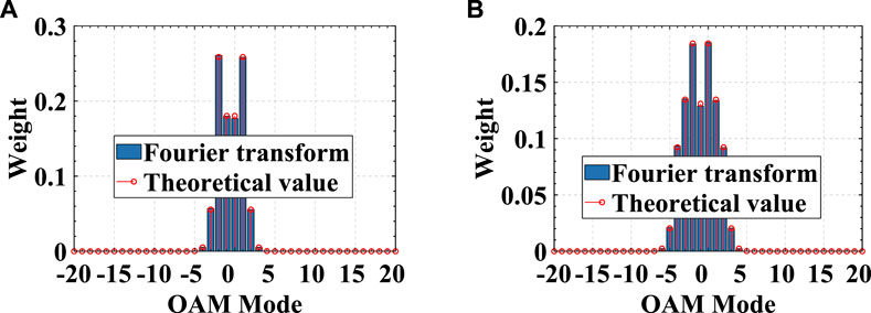
In addition, to investigate the OAM after beam collimation, Figure 8 compares the phase distribution of the observation plane perpendicular to the Z-axis and the beam axis after beam collimation. On the observation plane perpendicular to the original beam axis, the phase loses the spiral distribution characteristics. There is no prominent branch, and the phase distribution is close to the plane wave phase. However, the phase distribution still shows spiral characteristics on the observation plane perpendicular to the new beam axis, but the mode is impure. Therefore, Figure 9 compares the OAM spectrum of different targets after beam collimation. The theoretical value is approximated by the term

FIGURE 8. Beampattern before and after beam collimation in the pitch dimension. (A) Beampattern before beam collimation for
4.3 Analysis of Sidelobe Suppression
In this example, we analyze the effect of the sidelobe suppression proposed in Section 3.2. It is remarked that the simulations are based on time modulation and beam collimation. Figure 10 compares the beampattern of the CFDAs with different antenna patterns. We can see that the sidelobe suppression can be effectively realized by designing the antenna pattern. In particular, fx11 can significantly suppress the sidelobe.
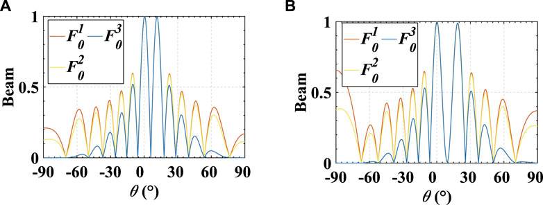
FIGURE 10. Beampattern of the CFDAs with different antenna patterns. (A) Beampattern for
5 Conclusion
In this article, combining the FDA structure with the vortex EM wave concept, we propose a beamforming method for the CFDA-based OAM. First, we establish a CFDA-based OAM-generating structure, based on which the feasibility of the CFDA to generate OAM is verified. Moreover, the generated OAM shows a range-time dependence owing to the introduced frequency offsets across the array antennas. Then, the characteristics of the generated OAM are investigated. Considering the application in radar imaging and target detection, the importance of beamforming is demonstrated. Therefore, for solving the mainlobe pointing changing with the OAM mode and the high sidelobe energy, we investigate the beamforming with the CFDA-based OAM. We calculate the angular offset of the mainlobe direction relative to the beam axis and thus achieve beam collimation by applying the steering vector to the array antennas. Furthermore, we select an appropriate antenna pattern for sidelobe suppression. The numerical results show the superior performance of the proposed beamforming method in the generation of range-time-dependent OAM based on CFDA. In future research, we will concentrate on applying the CFDA-based OAM in radar imaging and target detection.
Data Availability Statement
The original contributions presented in the study are included in the article/Supplementary Material. Further inquiries can be directed to the corresponding author.
Author Contributions
JG contributed to the conception and design of the study. JG and JX performed the statistical analysis. JG wrote the first draft of the manuscript. All authors contributed to manuscript revision, read, and approved the submitted version.
Conflict of Interest
The authors declare that the research was conducted in the absence of any commercial or financial relationships that could be construed as a potential conflict of interest.
Publisher’s Note
All claims expressed in this article are solely those of the authors and do not necessarily represent those of their affiliated organizations, or those of the publisher, the editors, and the reviewers. Any product that may be evaluated in this article, or claim that may be made by its manufacturer, is not guaranteed or endorsed by the publisher.
Acknowledgments
The authors would like to thank the Associate Editor and all the reviewers for their valuable and insightful comments and suggestions during the revision of this work.
References
1. Bahl P, Padmanabhan VN. Radar: An In-Building Rf-Based User Location and Tracking System. In: Proceedings IEEE INFOCOM 2000. Conference on computer communications. Nineteenth annual joint conference of the IEEE computer and communications societies (Cat. No. 00CH37064); March 2000; Tel Aviv, Israel. IEEE (2000). p. 775–84. vol. 2.
4. Yanhong Xu Y, Shi X, Xu J, Li P. Range-angle-dependent Beamforming of Pulsed Frequency Diverse Array. IEEE Trans Antennas Propagation (2015) 63:3262–7. doi:10.1109/tap.2015.2423698
5. Antonik P, Wicks MC, Griffiths HD, Baker CJ. Frequency Diverse Array Radars. In: Proceeding of the 2006 IEEE Conference on Radar; April 2006; Verona, NY, USA. IEEE (2006). p. 3.
6. Wang W-Q. Overview of Frequency Diverse Array in Radar and Navigation Applications. IET Radar, Sonar & Navigation (2016) 10:1001–12. doi:10.1049/iet-rsn.2015.0464
7. Huang J, Tong K-F, Woodbridge K, Baker C. Frequency Diverse Array: Simulation and Design. In: Proceeding of the 2009 IEEE Radar Conference; May 2009; Pasadena, CA, USA. IEEE (2009). p. 1–4. doi:10.1109/radar.2009.4976998
8. Antonik P. An Investigation of a Frequency Diverse Array. Ph.D. thesis. London: UCL University College London (2009).
9. Khan W, Qureshi IM, Saeed S. Frequency Diverse Array Radar with Logarithmically Increasing Frequency Offset. IEEE antennas wireless propagation Lett (2014) 14:499–502. doi:10.1109/lawp.2014.2368977
10. Wang B, Xie J-w., Zhang J, Ge J-a. Dot-shaped Beamforming Analysis of Subarray-Based Sin-Fda. Front Inf Tech Electron Eng (2019) 20:1429–44. doi:10.1631/fitee.1800722
11. Gao K, Wang W-Q, Cai J, Xiong J. Decoupled Frequency Diverse Array Range–angle-dependent Beampattern Synthesis Using Non-linearly Increasing Frequency Offsets. IET Microwaves, Antennas & Propagation (2016) 10:880–4. doi:10.1049/iet-map.2015.0658
12. Saeed S, Qureshi IM, Khan W, Salman A. Tangent Hyperbolic Circular Frequency Diverse Array Radars. J Eng (2016) 2016:23–8. doi:10.1049/joe.2015.0194
13. Basit A, Qureshi IM, Khan W, ur Rehman S, Khan MM. Beam Pattern Synthesis for an Fda Radar with Hamming Window-Based Nonuniform Frequency Offset. IEEE Antennas Wireless Propagation Lett (2017) 16:2283–6. doi:10.1109/lawp.2017.2714761
14. Liao Y, Tang H, Chen X, Wang W-Q. Frequency Diverse Array Beampattern Synthesis with taylor Windowed Frequency Offsets. IEEE Antennas Wireless Propagation Lett (2020) 19:1901–5. doi:10.1109/lawp.2020.3024710
15. Wang Z, Wang W-Q, Shao H. Range-azimuth Decouple Beamforming for Frequency Diverse Array with Costas-Sequence Modulated Frequency Offsets. EURASIP J Adv Signal Process (2016) 2016:1–9. doi:10.1186/s13634-016-0422-3
16. Xiong J, Wang W-Q, Shao H, Chen H. Frequency Diverse Array Transmit Beampattern Optimization with Genetic Algorithm. IEEE Antennas Wireless Propagation Lett (2016) 16:469–72. doi:10.1109/lawp.2016.2584078
17. Liao Y, Wang J, Liu QH. Transmit Beampattern Synthesis for Frequency Diverse Array with Particle Swarm Frequency Offset Optimization. IEEE Trans Antennas Propagation (2020) 69:892–901. doi:10.1109/tap.2020.3027576
18. Gui R, Wang W-Q, Pan Y, Xu J. Cognitive Target Tracking via Angle-Range-Doppler Estimation with Transmit Subaperturing Fda Radar. IEEE J Selected Top Signal Process (2018) 12:76–89. doi:10.1109/jstsp.2018.2793761
19. Wang W-Q, So H-C. Transmit Subaperturing for Range and Angle Estimation in Frequency Diverse Array Radar. IEEE Trans Signal Process (2014) 62:2000–11. doi:10.1109/tsp.2014.2305638
20. Wang W-Q. Subarray-based Frequency Diverse Array Radar for Target Range-Angle Estimation. IEEE Trans Aerospace Electron Syst (2014) 50:3057–67. doi:10.1109/taes.2014.120804
21. Khan W, Qureshi IM. Frequency Diverse Array Radar with Time-dependent Frequency Offset. IEEE Antennas Wireless Propagation Lett (2014) 13:758–61. doi:10.1109/lawp.2014.2315215
22. Chen K, Yang S, Chen Y, Qu S-W. Accurate Models of Time-Invariant Beampatterns for Frequency Diverse Arrays. IEEE Trans Antennas Propagation (2019) 67:3022–9. doi:10.1109/tap.2019.2896712
23. Tan M, Wang C, Li Z. Correction Analysis of Frequency Diverse Array Radar about Time. IEEE Trans Antennas Propagation (2020) 69:834–47. doi:10.1109/tap.2020.3016508
24. Chen B, Chen X, Huang Y, Guan J. Transmit Beampattern Synthesis for the Fda Radar. IEEE Antennas Wireless Propagation Lett (2018) 17:98–101. doi:10.1109/lawp.2017.2776957
25. Wang W-Q, So HC, Shao H. Nonuniform Frequency Diverse Array for Range-Angle Imaging of Targets. IEEE Sensors J (2014) 14:2469–76. doi:10.1109/jsen.2014.2304720
26. Lan L, Liao G, Xu J, Zhang Y, Liao B. Transceive Beamforming with Accurate Nulling in Fda-Mimo Radar for Imaging. IEEE Trans Geosci Remote Sensing (2020) 58:4145–59. doi:10.1109/tgrs.2019.2961324
27. Jingwei Xu J, Liao G, Zhu S, So HC. Deceptive Jamming Suppression with Frequency Diverse Mimo Radar. Signal Process. (2015) 113:9–17. doi:10.1016/j.sigpro.2015.01.014
28. Lan L, Xu J, Liao G, Zhang Y, Fioranelli F, So HC. Suppression of Mainbeam Deceptive Jammer with Fda-Mimo Radar. IEEE Trans Vehicular Tech (2020) 69:11584–98. doi:10.1109/tvt.2020.3014689
29. Ge J, Xie J, Wang B. A Cognitive Active Anti-jamming Method Based on Frequency Diverse Array Radar Phase center. Digital Signal Process. (2021) 109:102915. doi:10.1016/j.dsp.2020.102915
30. Tamburini F, Mari E, Sponselli A, Thidé B, Bianchini A, Romanato F. Encoding many Channels on the Same Frequency through Radio Vorticity: First Experimental Test. New J Phys (2012) 14:033001. doi:10.1088/1367-2630/14/3/033001
31. Allen L, Beijersbergen MW, Spreeuw R, Woerdman J. Orbital Angular Momentum of Light and the Transformation of Laguerre-Gaussian Laser Modes. Phys Rev A (1992) 45:8185. doi:10.1103/physreva.45.8185
32. Mari E, Spinello F, Oldoni M, Ravanelli RA, Romanato F, Parisi G. Near-field Experimental Verification of Separation of Oam Channels. IEEE Antennas Wireless Propagation Lett (2014) 14:556–8. doi:10.1109/lawp.2014.2369536
33. Mohammadi SM, Daldorff LK, Bergman JE, Karlsson RL, Thidé B, Forozesh K, et al. Orbital Angular Momentum in Radio—A System Study. IEEE Trans Antennas Propagation (2009) 58:565–72. doi:10.1109/tap.2009.2037701
34. Yuan T, Cheng Y, Wang H, Qin Y. Beam Steering for Electromagnetic Vortex Imaging Using Uniform Circular Arrays. IEEE Antennas Wireless Propagation Lett (2016) 16:704–7. doi:10.1109/lawp.2016.2600404
35. Liu K, Cheng Y, Yang Z, Wang H, Qin Y, Li X. Orbital-angular-momentum-based Electromagnetic Vortex Imaging. IEEE Antennas Wireless Propagation Lett (2014) 14:711–4. doi:10.1109/lawp.2014.2376970
36. Liu H, Liu K, Cheng Y, Wang H. Microwave Vortex Imaging Based on Dual Coupled Oam Beams. IEEE Sensors J (2019) 20:806–15. doi:10.1109/jsen.2019.2943698
37. Liu K, Cheng Y, Li X, Jiang Y. Passive Oam-Based Radar Imaging with Single-In-Multiple-Out Mode. IEEE Microwave Wireless Components Lett (2018) 28:840–2. doi:10.1109/lmwc.2018.2852146
38. Liu H, Wang Y, Wang J, Liu K, Wang H. Electromagnetic Vortex Enhanced Imaging Using Fractional Oam Beams. IEEE Antennas Wireless Propagation Lett (2021) 20:948–52. doi:10.1109/lawp.2021.3067914
39. Liu K, Cheng Y, Gao Y, Li X, Qin Y, Wang H. Super-resolution Radar Imaging Based on Experimental Oam Beams. Appl Phys Lett (2017) 110:164102. doi:10.1063/1.4981253
40. Liu K, Li X, Gao Y, Cheng Y, Wang H, Qin Y. High-resolution Electromagnetic Vortex Imaging Based on Sparse Bayesian Learning. IEEE Sensors J (2017) 17:6918–27. doi:10.1109/jsen.2017.2754554
41. Zeng Y, Wang Y, Chen Z, Zhang J, Zhang J. Two-dimensional Oam Radar Imaging Using Uniform Circular Antenna Arrays. In: 2020 14th European Conference on Antennas and Propagation (EuCAP); March 2020; Copenhagen, Denmark. IEEE (2020). p. 1–4. doi:10.23919/eucap48036.2020.9135917
42. Ghaleh SR, Ahmadi-Kandjani S, Kheradmand R, Olyaeefar B. Improved Edge Detection in Computational Ghost Imaging by Introducing Orbital Angular Momentum. Appl Opt (2018) 57:9609–14. doi:10.1364/ao.57.009609
Keywords: vortex electromagnetic (EM) wave, orbital angular momentum (OAM), frequency diverse array (FDA), circular FDA (CFDA), beamforming
Citation: Ge J and Xie J (2022) Beamforming in the Generation of Range-Time-Dependent Orbital Angular Momentum Based on the Circular Frequency Diverse Array. Front. Phys. 10:900665. doi: 10.3389/fphy.2022.900665
Received: 21 March 2022; Accepted: 12 May 2022;
Published: 05 July 2022.
Edited by:
Nanrun Zhou, Nanchang University, ChinaReviewed by:
Sushank Chaudhary, Quanzhou Institute of Equipment manufacturing (CAS), ChinaHasan Mir, American University of Sharjah, United Arab Emirates
Copyright © 2022 Ge and Xie . This is an open-access article distributed under the terms of the Creative Commons Attribution License (CC BY). The use, distribution or reproduction in other forums is permitted, provided the original author(s) and the copyright owner(s) are credited and that the original publication in this journal is cited, in accordance with accepted academic practice. No use, distribution or reproduction is permitted which does not comply with these terms.
*Correspondence: Jiaang Ge, Z2VqaWFhbmcwMzEzQDE2My5jb20=
 Jiaang Ge
 Junwei Xie