 Bailin Lin1
 Xinqi Chen
- 1School of Physics and Mechanical Electrical Engineering, Hubei University of Education, Wuhan, China
- 2School of Mathematics and Physics, Jingchu University of Technology, Jinmen, China
- 3Hubei Engineering Technology Research Center of Environmental Purification Materials, Institute of Materials Research and Engineering, Hubei University of Education, Wuhan, China
In this experiment, the stable output of a dual-frequency laser source is obtained by an acousto-optic modulator due to the Bragg diffraction effect. Furthermore, the non-polarized dual-laser heterodyne interferometer is designed to measure the micro-movement of stacked piezoelectric (PZT) ceramic. This micro-movement can be dynamically determined by comparing the phase difference between the conference beam and measuring beam. The results indicate that the micro-movement of PZT ceramic changes linearly with the driven-voltage in the range of 0–30 V and the sensitivity of movement to voltage is 58.3 nm/V, which is very close to the theoretical value and this laser heterodyne interferometer can be applied for calibrating parameters of PZT ceramic.
Introduction
The laser heterodyne interferometer can measure the displacement, velocity, and acceleration of vibration target in real-time [1–3]. It has the characteristics of non-contact, anti-interference, high precision, and so on, and has been widely used in the precision displacement measurement of micro-nano devices [4,5]. At present, the principle of a laser interferometer for measuring length (displacement or distance) is still based on the Michelson interferometer. For a single-frequency laser interferometer, the beam from the laser is collimated and divided into two channels by a beam-splitter, and then reflected from a fixed mirror and a movable mirror respectively. When the movable mirror moves, the intensity change of interference fringes is transformed into a voltage signal by the photoelectric conversion element (photoelectric sensor) and an electronic circuit (signal amplifier). Then, after shaping and amplifying the input signal acquisition system, the phase difference is calculated. Finally, the displacement of the movable mirror is calculated by the phase difference. Phase measurement of single-frequency laser interferometer belongs to optical intensity measurement, many internal (electronic noise and long-term drift, etc.) and external factors environmental changes, such as temperature, atmospheric pressure, refractive index changes will affect the measurement results [6,7].
Compared with single-frequency laser interferometry, the displacement is determined by measuring the phase difference of two signals directly. The displacement (i.e., the optical path difference) information is contained in the beat signal produced by the interference of the two frequency beams, which has higher accuracy and can overcome the DC drift of the single-frequency interferometer [8]. At present, the Zeeman Effect and Acousto-Optical Modulators (AOM) are the main methods to obtain dual-frequency laser output [9]. In general, compared with Zeeman Effect method, the frequency difference of the acousto-optic modulation method is relatively large (up to 20 MHz), and its frequency stability is relatively high. In practice, the laser diffracted by the acousto-optic modulator has the disadvantages of diffraction secondary and frequency shift. Also, have an impact on the measurement accuracy of nanometer level, an effective method is to use the method of double acousto-optic modulation, of course, this light path collimation adjustment and optimization put forward higher requirements [10].
In this experiment, the He-Ne laser is used as the light source and two acousto-optic modulators of the same model are used. A two-frequency laser with a tunable frequency difference in the range of 2 MHz was obtained and used to measure the micro displacement of stacked PZT ceramics. The stable and reliable experimental results were obtained, and the sensitivity of micro-movement of PZT ceramics to voltage and the linear operating voltage range were obtained.
Materials and Methods
The formation of the optical beat requires that the two beams superimposed on each other have a small frequency difference. To obtain two beams with such characteristics, the laser beam can be managed to produce a fixed frequency shift. This experiment is realized by the interaction of ultrasonic and laser in the medium. When the ultrasonic propagates in the medium (RF signal applied to the medium), it will cause the elastic strain of the medium to change periodically in time and space, and also lead to the corresponding periodic change of refractive index. When the light beam passes through the medium with an ultrasonic wave, it will produce a diffraction phenomenon. This acousto-optic effect is essentially a special kind of elastic-optic effect. In this case, the ultrasonic medium can be regarded as an individual grating, the grating spacing is equal to the wavelength of the acoustic wave.
According to the ultrasonic frequency and the length of acousto-optic interaction, acousto-optic diffraction can be classified into three categories: Raman-Nath diffraction, Bragg diffraction, and mixed diffraction. Bragg diffraction occurs when the ultrasonic frequency is high, the acousto-optic region is long, and the incident light incidence is inclined to a certain angle. By controlling the incident ultrasonic power and incidence angle, all incident light power can be converted to the first-order diffraction light power. The frequency of the zero-order beam is the same as the frequency f of the incoming beam, while the frequencies of the +1 and -1 orders are f0+fm and f0-fm, respectively, (fm is the frequency shift generated by the incident light passing through the acousto-optic crystal), and when the angle between incident light and the acoustic plane satisfies certain conditions, The diffracted light in the medium will interfere with each other, and each higher-order will cancel each other. Only 0 order, + 1 order (or -1 order) exit light will appear.
For the first-order Bragg diffraction angle, the angle satisfied can be expressed as
Where λC and λS are the wavelengths of incident laser and ultrasonic waves, respectively.
In the experiment, the working voltage of the acousto-optic modulator is 24 V, and we take +1 order diffraction for both beams, as shown in Figure 1. One of the acousto-optic modulators is applied with a frequency of 80 MHz, and the other acousto-optic modulator is applied with a frequency of 82 MHz so that the frequency difference between the two beams after +1-order diffraction is 2 MHz.
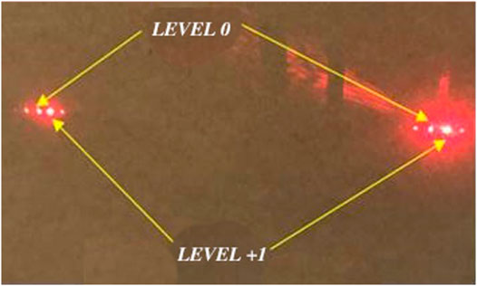
FIGURE 1. Acousto-optic diffraction produced by He-Ne laser passing through an acousto-optic modulator.
A schematic diagram of a non-polarized laser heterodyne interferometer based on the acousto-optic effect and a diagram of an experimental device is shown in Figures 2A,B, respectively, wherein the mirror is fixed to an adjustable frame by a stacked PZT ceramic (as seen in Figure 2B). The laser beam from the He-Ne laser is divided into two beams by the beam splitter BS, and the beam with frequency f1 and f2 is generated by the acousto-optic frequency shifter. The two beams of light are respectively divided into two beams by the beam splitter, and the upward reflecting frequency f1 and f2 beams are reflected by the beam-splitter to form a reference beam and receive the interference signal through the photoelectric detector PD1. In addition, the directly transmitted f1 and f2 beams pass through the mirrors M1 and M2 respectively and then are reflected downwards by the spectroscope to produce interference, forming the measuring beam, and receiving the interference signal by the photoelectric detector PD2. At this time, the reference beam and the measuring beam have a constant phase difference, and when the mirror located in the measuring path moves (e.g., M2 moves back and forth), When the optical path of the measuring light is changed, its phase is also changed, so the phase of the interference beat measurement signal is changed. By comparing the phase difference between the reference beam signal and the measured beam signal on an oscilloscope, the variation of the optical path difference of the two arms of the interferometer and the displacement of the movable mirror can be obtained.
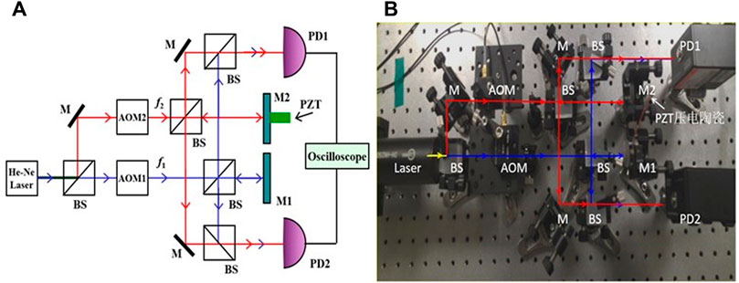
FIGURE 2. (A) Schematic diagram of optical path and (B) experimental setup diagram of non-polarized laser heterodyne interference. BS: Beam splitter, M: Reflector, AOM: acousto-optic modulator, PD: Photo-detector.
For the reference beam, the electric fields of frequencies f1 and f2 can be expressed as [11],
Where φr1, φr2 are the corresponding phases. Thus obtaining the composite intensity of the reference beam,
Because the frequency of the first three terms in formula 3 is very high, beyond the frequency response range of the general photoelectric detector, the former three terms can only output (time) average value, for direct flow. The last term is the interference term, which is the beat signal formed by the interference of two laser beams, the intensity signal received by the detector is,
Where φ01-φ02 is the initial phase difference.
For the measurement signal, the interference signal generates an extra optical path difference due to the difference in the optical path and the optical path change caused by the movement of the mirror M2, the light intensity can be expressed as,
Where Δϕ = 4 πn (L1/λ1 - L2/λ2), n is the refractive index of the environment (the refractive index of air n ≈ 1).
When the frequency f1 and f2 are not much different, it can be assumed that λ1≈λ2≈λ; comparing the phase of the reference signal and the measured signal, the phase difference is:
In the experiment, a digital oscilloscope can be used to observe and measure the phase difference between the reference signal and the measurement signal to obtain the optical path difference, and then obtain the movement of the mirror M2 △L. When a different DC voltage is applied to the PZT ceramics, △L changes, so that the phase difference between the two also changes. The relationship between the phase difference and the voltage is measured, and the relationship between the tiny displacement of the PZT ceramic and the voltage can be obtained.
Experimental Results and Data Analysis
To observe a stable beat signal in the experiment, the collimation adjustment of the optical path is extremely important. Starting from the placement of the laser light source, every time an optical lens is inserted, a fixed height aperture diaphragm must be moved back and forth to check the collimation of the light path. When the light path is collimated, the two beat frequency signals observed by the oscilloscope are shown in Figure 3A. The acousto-optic frequency shifter YSGMN-2 used in the experiment can produce a frequency shift of about 80 MHz for the He-Ne laser based on the original frequency. Set the parameters of the two acousto-optic frequency shifters, so that the frequency difference between f1 and f2 is 2 MHz. The frequency difference setting value of the frequency converter is almost the same, the waveform is stable, and the signal-to-noise ratio is high, indicating that the optical path design and collimation adjustment are reasonable. Figure 3A shows the result of real-time sampling. To facilitate the measurement, the sampling can be averaged to make the waveform more stable and reduce the error of the phase measurement. Figure 3B shows the result obtained after eight samplings are averaged, and the measurement result of the phase difference is given.
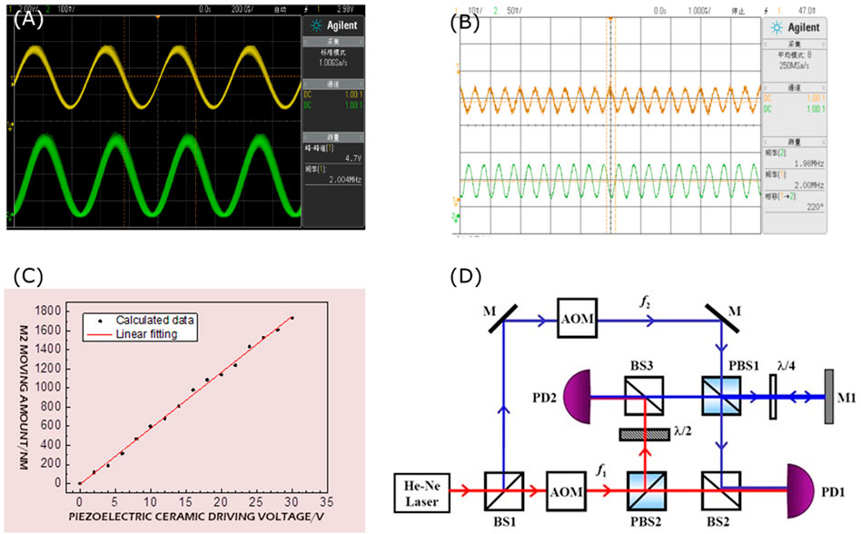
FIGURE 3. (A) Measurement results from real-time sampling, and (B) measurements after eight averaging. (C) The relationship between the amount of movement of the mirror M2 and the voltage. (D) Optical path of polarization dual-frequency laser interference system. PBS: Polarization beam splitter, λ/2: half-wave plate, λ/4: quarter-wave plate.
Calibrate the initial phase difference as the starting point, apply different DC drive voltages to the PZT ceramics, observe the movement of the measured signal waveform and record the corresponding phase difference. The movement of the mirror M2 can be calculated by Eq 7 (here, the laser wavelength takes 632.8 nm), which is the expansion and contraction value of PZT ceramics. The measurement was carried out 3 times, with 15 sets of data each time, and the results are shown in Table 1.
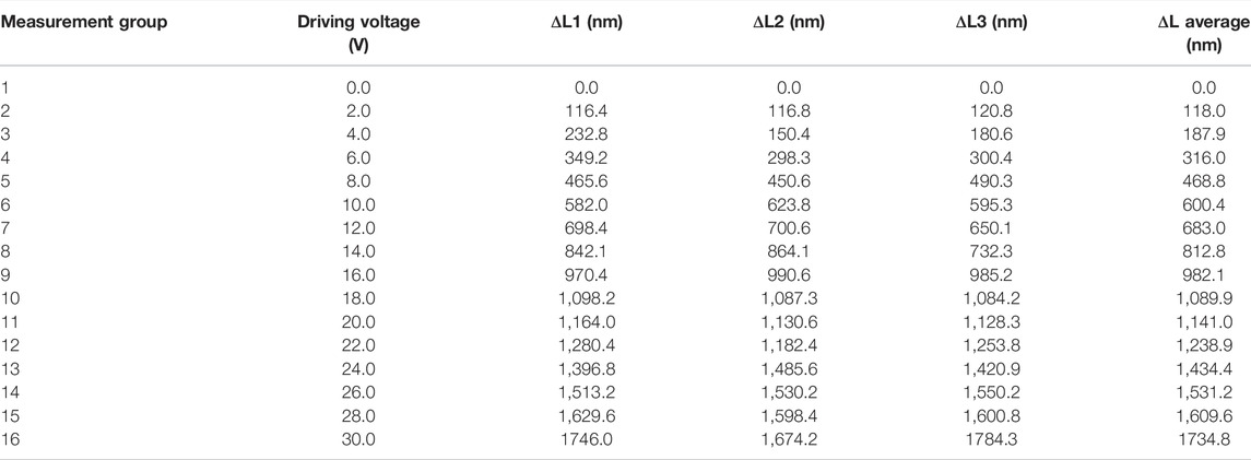
TABLE 1. Measurement results of the movement of the mirror M2.
Figure 3C shows the relationship between the movement of the mirror M2 and the voltage. Through linear fitting, the relationship between the PZT ceramic expansion and contraction ΔL and the driving voltage V is given as follows:
The results show that in the range of 0–30 V, the PZT ceramic expansion and contraction ΔL have a good linear relationship with the driving voltage. The linear correlation coefficient is 0.987, and the sensitivity of ΔL to voltage is about 58.3 nm/V. The stacked PZT ceramic model used here is RP150/10, its theoretical reference value is 60 nm/V, and the allowable error fluctuation range is ±10%. It can be seen that our actual measurement results are controlled within the error range, indicating that the experimentally designed dual-frequency heterodyne interferometer based on the acousto-optic effect has good measurement accuracy and can be used for PZT coefficients in PZT ceramic experimental applications. Parameter calibration.
In the tactual measurement, it is difficult to accurately read the phase difference. The fluctuation and pulsation of numerical value are obvious, which requires high stability of the environment and optical platform. At the same time, many factors affect the measurement of small displacement, including the quality of laser source, the diffraction efficiency of acousto-optic frequency shifter, the response sensitivity of photoelectric detector, and the nonlinear error caused by optical transmission [12]. In addition, the use of a non-polarized beam splitter in the experiment may produce birefringence, when the direction of birefringence is inconsistent with the two polarization directions of the laser beam, the beam will change from linear polarization to elliptic polarization after passing the beam splitter, resulting in errors in the measured phase changes [13].
To further improve the measurement accuracy, consider designing an optical path based on polarization-based heterodyne interference, as shown in Figure 3D. The basic process is similar to non-polarized heterodyne interference, except that the beam splitter uses a polarizing beam splitter PBS. The laser is divided into two beams by BS1, and the beams with frequencies f1 and f2 are generated by the acousto-optic frequency shifter. After the beam of frequency f1 passes through the polarizing beam splitter PBS2, the S-polarized light (perpendicular to the plane of lightwave incidence and reflection) is reflected (f1S), and the light transmitted through PBS2 is P-polarized (f1P). The beam of frequency f2 passes through the mirror M and then passes through the polarizing beam splitter PBS1. The transmitted P-polarized light (f2P) is reflected by the beam splitter BS2 and forms a beat with the P-polarized light (f1P) of frequency f1 transmitted through BS2. The frequency signal, received by the photo-detector PD1, is the reference beam. The S-polarized light reflected by PBS2 at frequency f1 passes through the half-wave plate and becomes P-polarized light (f1P); the S-polarized light (f2S) at frequency f2 reflected by PBS1 passes through the quarter-wave plate and becomes circularly polarized light., and then reflected by the mirror M1 that can move back and forth, when it passes through the quarter-wave plate, it becomes P-polarized light (f2P), after passing through the polarization beam splitter PBS1 and beam splitter BS3, and the frequency reflected by BS3. The P-polarized light (f1P) of f1 together forms a beat signal, which is received by the photo-detector PD2 as the measuring beam. There are many other schemes for the measurement optical path of polarization-based dual-frequency laser interference, and the principles are almost the same, so we will not describe them here.
Conclusion
The laser heterodyne interference technology based on the acousto-optic effect is an effective method to measure a small amount of movement. The frequency difference generated by it is greater than the frequency difference generated by the Zeeman Effect. The Bragg diffraction effect of the double acousto-optic frequency shifter can be used for two beams. The frequency difference of the laser can be adjusted, and the measurement of the small amount of movement can be realized through the ordinary digital oscilloscope. In this experiment, the relationship between the expansion and contraction of PZT ceramics and the voltage is measured, and the result is consistent with the theoretical reference value, and the measurement accuracy is high. The optical path collimation adjustment and related laser interference principles involved in this experiment will greatly promote the cultivation of the optical path design ability of undergraduates majoring in physics, optoelectronics, and mechanics.
Data Availability Statement
The original contributions presented in the study are included in the article/Supplementary Material, further inquiries can be directed to the corresponding author.
Author Contributions
All authors listed have made a substantial, direct, and intellectual contribution to the work, and approved it for publication.
Funding
National Natural Science Foundation of China (51702091) and the Research Start-up Funding of Hubei University of Education (19RC02). Innovation and Entrepreneurship Training program for College students (S202114099050).
Conflict of Interest
The authors declare that the research was conducted in the absence of any commercial or financial relationships that could be construed as a potential conflict of interest.
Publisher’s Note
All claims expressed in this article are solely those of the authors and do not necessarily represent those of their affiliated organizations, or those of the publisher, the editors and the reviewers. Any product that may be evaluated in this article, or claim that may be made by its manufacturer, is not guaranteed or endorsed by the publisher.
References
1. Gelmini E., Minoni U., Docchio F. Tunable, Double-Wavelength Heterodyne Detection Interferometer for Absolute-Distance Measurements. Opt Lett (1994) 19(3):213–215. doi:10.1364/OL.19.000213
2. Takita A., Ebara H., Fujii Y. Dual Beat-Frequencies Laser Doppler Interferometer. Rev Scientific Instr (2011) 82(12):123111. doi:10.1063/1.3669785
3. Wang L.-J., Zhang M., Zhu Y., Lu S., Yang K.-M. A Displacement Measurement System for Ultra-precision Heterodyne Littrow Grating Interferometer. Guangxue Jingmi Gongcheng/Optics Precision Eng (2017) 25(12):2975–2985. doi:10.3788/ope.20172512.2975
4. Lou Y., Li Z., Yan L., Chen B., Jian J. A Phase Differential Heterodyne Interferometer for Simultaneous Measurement of Straightness Error and Displacement. Opt Commun (2021) 497:127195. doi:10.1016/j.optcom.2021.127195
5. Fomiryakov E., Kharasov D., Nikitin S., Nanii O., Treshchikov V. New Approach to Laser Characterization Using Delayed Self-Heterodyne Interferometry. J Lightwave Technol (2021) 39(15):5191–5196. doi:10.1109/JLT.2021.3082263
6. Zhang P., Wu J., Huang G. Active Compensation Method for Nonlinear Error of Single-Frequency Laser Interferometer Vibrometer. Prog Laser Optoelectronics (2018) 55(8):318–325. doi:10.3788/lop55.081204
7. Chen X.-Q., Fan S.-J., Han C., Wu T., Wang L.-J., Jiang W, et al. Multiscale Architectures Boosting Thermoelectric Performance of Copper Sulfide Compound. Rare Met (2021) 40(8):2017–2025. doi:10.1007/s12598-020-01698-6
8. Jin Y., Zhang S., Li Y., Guo J., Li J. Zeeman-birefringence He-Ne Dual Frequency Lasers. Chin Phys Lett (2001) 18(4):533–536.
9. Suo R., Fan Z., Li Y., Zhang S. Dual-frequency Laser Interferometer Present State and Development. Laser and Infrared (2004) 34(4):251–253.
10. Li Y., Xiang L., Zhang W., Huang M., Wu Z., Kong X. Frequency Difference Detection of Dual Acousto-Optic Modulators Based on Spectrum Correction. Prog Laser optoelectronics (2015) 52(5):116–121. doi:10.3788/lop52.051205
12. Zhao Y., Zhou T., Li D. Influence of Acousto-Optic Modulator Characteristics on Measurement Accuracy in Heterodyne Interferometer. Acta Optica Sinica (1999) 19(10):1368–1374.
Keywords: acousto-optic modulator, heterodyne interference, phase difference, laser, piezoelectric ceramic
Citation: Lin B, Dai W, Sun J, Xiao M, He Z, Wu J and Chen X (2022) Micro-Movement Measured by Laser Heterodyne Interferometer Based on Acousto-Optic Effect. Front. Phys. 10:890194. doi: 10.3389/fphy.2022.890194
Received: 05 March 2022; Accepted: 29 April 2022;
Published: 16 May 2022.
Edited by:
Jifeng Liu, Dartmouth College, United StatesReviewed by:
Chen Qing, Yunnan Normal University, ChinaGuang Yang, Al-Mustansiriya University, Iraq
Jie Yang, Wuhan University of Technology, China
Yanhui Niu, Guizhou Education University, China
Wending Zhang, Northwestern Polytechnical University, China
Copyright © 2022 Lin, Dai, Sun, Xiao, He, Wu and Chen. This is an open-access article distributed under the terms of the Creative Commons Attribution License (CC BY). The use, distribution or reproduction in other forums is permitted, provided the original author(s) and the copyright owner(s) are credited and that the original publication in this journal is cited, in accordance with accepted academic practice. No use, distribution or reproduction is permitted which does not comply with these terms.
*Correspondence: Xinqi Chen, Y2hlbnhpbnFpQGh1ZS5lZHUuY24=