 Wenxing An
 Xiaochi Zhang1
 Yu Luo
 Jian Wang
- 1The Tianjin Key Laboratory of Imaging and Sensing Microelectronic Technology, School of Microelectronics, Tianjin University, Tianjin, China
- 2The Department of Electronic Engineering, Tsinghua University, Beijing, China
Abstract—A novel double-layer transmitarray element is presented at 60 GHz with linearly- and circularly-polarized characteristics. A planar frequency-selective structure using the complementary design is adopted to augment the element performance for millimeter-wave applications. By integrating two different types of structure, i.e. cross and slot type, the compensation phase range is extended effectively with a satisfactory transmission magnitude. A transmitarray prototype is fabricated and tested to verify this double-layer complementary design. The measured gain at 60.5 GHz is 33.1 dBi with an aperture efficiency of 42.15%. Low side-lobe and cross-polarization levels are obtained. The proposed double-layer complementary design can reduce the structure complexity effectively and offer a high aperture efficiency at a low cost, which can be a potential candidate for the millimeter-wave transmitarray.
1 Introduction
Recently, transmitarray antenna has become a popular research item. Compared with the traditional lens antenna, the transmitarray aperture can be a planar frequency-selective surface, which makes it easy integration, visual invisibility, and economical fabrication with PCB technology. Many transmitarray antennas have been investigated with diverse performances such as wideband [1], multiple bands [2], low profile [3], multiple beams [4], and beam scanning [5].
Many devices have been reported for the millimeter-wave band near 60 GHz [6–8]. A three-layer linearly polarized transmitarray antenna was presented in [9] for millimeter-wave applications. Employing a slot-coupling method, a triple-layer linearly polarized transmitarray was proposed in [10]. Although satisfactory performances have been realized, these designs have at least three metallic layers that make the structure relatively complicated. A dual-layer transmitarray was proposed for the 77-GHz automotive radar applications [11]. However, the proposed element can only provide 0° and 180° phase differences, which would result in a relatively large phase error and lower aperture efficiency. A dual linearly polarized transmitarray was presented at D-band with a peak gain of 32 dBi and aperture efficiency of 32% at 150 GHz [12]. It is discussed in [13] that at least three metallic layers are required to achieve a compensation phase range of nearly 360°and -1-dB magnitude simultaneously. To reduce the structural complexity, the double-layer element has been investigated and reported. A double-layer transmitarray element with metallic vias was proposed [14, 15]. It was further investigated in [16–18] with improved performance. A two-layer linearly-polarized metal-only TA was presented in [19].
For the 60-GHz millimeter-wave and even higher frequency band, transmitarrays with a simple structure are desired for easy fabrication and low cost. Then, some double-layer designs without vias are investigated. A double-layer planar lens antenna was presented in [20] using a gradient metasurface structure with a measured aperture efficiency of 24.6%. A double-layer design from [21] can achieve a high aperture efficiency of 60.2% using a circular polarization conversion approach for circular polarization. Recently, a conformal transmitarray was developed in [22] using a dual-layer Huygens element with single linear polarization. It has a measured gain of 20.6 dBi with an aperture efficiency of 47%. Although the above designs have achieved satisfactory performance, it is still difficult to accommodate both linear and circular polarizations simultaneously to meet the application requirements of different occasions. Recently, a planar transmitarray element based on a complementary frequency-selective structure was reported in [23] with an extended compensation phase range. It can be adapted potentially for millimeter-wave applications.
A complementary double-layer transmitarray element is presented for the millimeter-wave band in this letter. The element performance is improved effectively based on the hybrid design combining cross and slot-type structures with linear and circular polarization characteristics. Then, a transmitarray antenna is fabricated for verification. Satisfactory radiation performance has been achieved with a measured gain of 33.1 dBi. The measured aperture efficiency is 42.15% with low side-lobe and cross-polarization levels.
2 Proposed Double-Layer Complementary Element
The double-layer complementary element is shown in Figure 1. The element size is 2.98 mm in the X- and Y-directions. Two identical metallic structures are printed on the top and bottom of the Rogers-5880 substrate with a thickness of 20 mil. The detailed parameters are in Table 1.
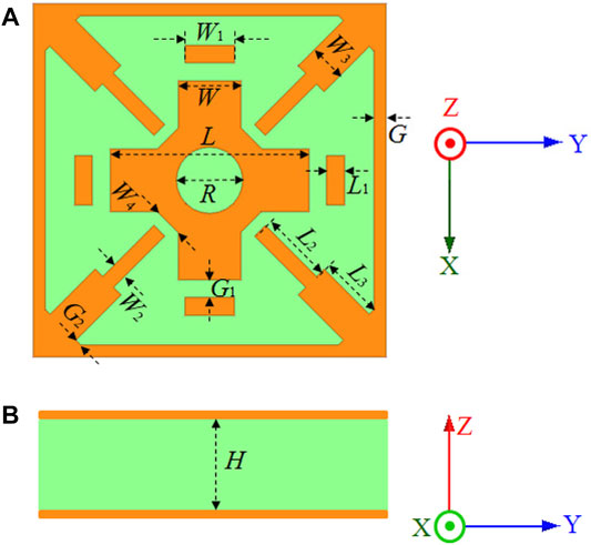
FIGURE 1. Structure of the double-layer element. (A) Top view, (B) Side view.

TABLE 1. Antenna element parameters (mm).
The metallic structure consists of modified cross, slot, and parasitic structures. The slot-type structure has four stubs at the corners with lengths L2, L3, and widths W2, W3. The cross has the length L and width W with a circular slot carved at the center. Four parasitic rectangular patches with the sizes of L1 and W1 are distributed around the cross with a gap of G1. All metallic structures are distributed symmetrically. The central symmetry structure makes it suitable for both linear and circular polarizations.
Using structural design freedom, two complementary elements with different stub and cross sizes are utilized to extend the compensation phase range, as shown in Figure 2. For element 1, the stub is relatively short with L2 = 0.37 mm and L3 = 0.05 mm, respectively. The diameter of the central slot is with the equation D = –1.75L2+4.52L–2.17. The phase range is obtained by changing the cross length L from 0.9 to 1.67 mm. For element 2, the stub lengths L2 and L3 are 0.61 and 0.54 mm, respectively. D is with the equation of D=(1.96 mm–L)×2. The L varies between 1.68 and 1.9 mm. The element performances with a normal incidence at 60 GHz are plotted in Figure 2. The phase range of element 1 is from −59° to −141° with a transmission magnitude better than −1.5 dB. For element 2, the −1.5-dB phase range is from 40° to 133°. The phase range between −180° and 180° can be covered with a maximum phase error of 55° based on these two elements. So a double-layer complementary element with an extended phase range is realized for the 60-GHz millimeter-wave band.
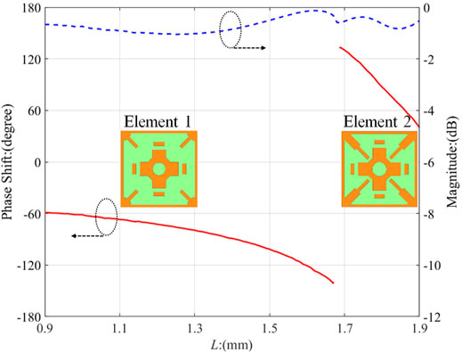
FIGURE 2. Phase and magnitude performance of the complementary element at 60 GHz with normal incidence.
3 Antenna Analysis
The element performances under oblique incidence are simulated with the TE and TM sources. The phase and magnitude performances are plotted in Figure 3 and. 4. It is observed in Figure 3A that the maximum phase error for TE source is 61° between the normal and oblique incidence with θ = 25° and φ = 45°. For the TM source in Figure 3B, the maximum phase error is 49° between the normal and oblique incidence with θ = 25° and φ = 0°. In Figure 4, the maximum magnitude error for TE source is −1.18 dB between the normal and oblique incidence with θ = 25° and φ = 45° while the maximum magnitude error for TM source is −2.5 dB between the normal and oblique incidence with θ = 25° and φ = 0°.
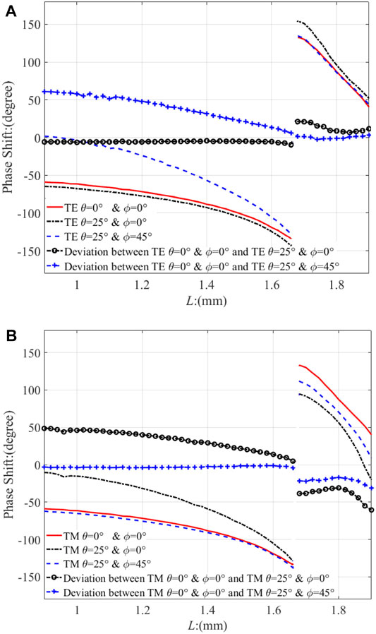
FIGURE 3. Phase performance under oblique incidence: (A) TE, (B) TM.
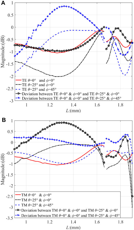
FIGURE 4. Magnitude performance under oblique incidence: (A) TE, (B) TM.
As elements 1 and 2 can cover the phase ranges from −180° to 0° and from 0° to 180° respectively, the effective current distributions are plotted for analysis, which is depicted in Figure 5 with the cross length L = 1.68 mm.
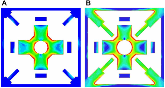
FIGURE 5. Effective current distributions with L = 1.68 mm: (A) Element 1, (B) Element 2.
For element 1, it is observed in Figure 5A that most currents distribute on the cross while there are few currents on the slot-type structure due to a relatively small stub length. The slot-type structure has little effect on the element performance when the stub length is electrically small, so the slot-type structure has limited influence on element 1.
In Figure 5B, the currents are on cross and slot-type structures of element 2. The slot-type structure affects the element performance when the stub length is comparable to the wavelength. The instantaneous current distributions are in Figure 6. The cross is excited at the reference time point of t in Figure 6A. The slot-type structure is excited at the time point of t + T/6 in Figure 6B where T represents one cycle. It is noticed that the slot-type and cross structures are not excited simultaneously but with a time interval of T/6. The introduced slot-type structure can offer an extra phase shift compared with element 1, so the transmission phase is shifted from the negative range to the positive range, as shown in Figure 2. It can be concluded that the cross is responsible for the performance of element 1. Both the cross and slot-type structures affect the performance of element 2. They are stimulated successively within half cycle.
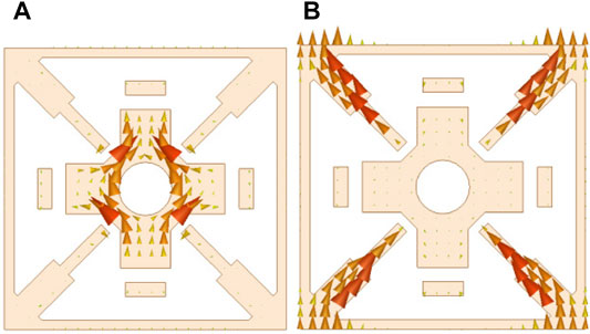
FIGURE 6. Instantaneous current distributions of element 2 with L = 1.68 mm at different time points: (A) t, (B) t+T/6.
4 Experimental Verification
To verify the proposed double-layer frequency-selective structure, a transmitarray antenna with a diameter of 113 mm is designed and fabricated, as shown in Figure 7. It includes 1,060 elements with a cross length varying between 0.9 and 1.89 mm. A linearly-polarized horn antenna with a gain of 18.25 dBi at 60 GHz is employed to illuminate the antenna aperture in the normal direction. The height is optimized to be 140 mm. Based on the element and feed characteristics, the compensation phase of each element is calculated [24]. A full-wave simulation is conducted using CST software. The calculated radiation patterns are plotted in Figure 8. In Figure 9, the antenna gain at 60 GHz is calculated to be 33.16 dBi with the simulated aperture efficiency of 43.7% [25].
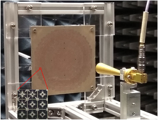
FIGURE 7. Antenna prototype based on the proposed double-layer complementary element.

FIGURE 8. Measured and simulated patterns at 60 GHz: (A) E-plane, (B) H-plane.

FIGURE 9. Measured and simulated gains.
An LPKF ProtoLaser system is employed for the aperture fabrication while the antenna prototype is assembled and tested in an anechoic chamber. The measured radiation patterns and gain are plotted in Figures 8, 9, respectively. The measured gain at 60 GHz is 31.95 dBi with an aperture efficiency of 34.5% while the maximum gain is 33.1 dB at 60.5 GHz with an aperture efficiency of 42.15%. The 3-dB-gain bandwidth is from 58.4 to 61.9 GHz with a relative bandwidth of 5.9%. It is observed in Figure 8 that the measured main beam almost overlaps with the simulation result. The measured side-lobe levels are below −24.2 dB at E-plane and −22.3 dB at H-plane while the maximum cross-polarization level is -29.1 dB. It is observed that the measured gain is 1.2 dB lower than the simulated one at 60 GHz while the simulated and measured gains are almost equal at 60.5 GHz.
There are certain discrepancies between the simulation and measurement results. Firstly, certain elements are not etched precisely. It would introduce additional phase and magnitude errors. Secondly, the tramsmitarray prototype is assembled manually, the assembly errors with the radiation aperture and feeding horn are inevitable. Finally, the antenna is supported by a metallic frame. It would introduce more reflections and refractions, resulting in certain influences on the radiation patterns.
The proposed transmitarray is compared with some existing millimeter-wave designs in Table 2. Based on the traditional three-layer frequency-selective structure [9, 10], aperture efficiency of more than 42% has been realized with 3-dB-gain bandwidths of more than 15%. However, they are only suitable for linear-polarized applications with a relatively complex structure. A linearly-polarized dual-layer transmitarray was proposed [11] at 77 GHz with a relatively lower aperture efficiency of 19.3%. A triple-layer transmitarray antenna has been presented at D-band with both linear and circular polarization characteristics [12]. The measured gain is 32 dBi with an aperture efficiency of 32%. To improve the aperture efficiency and to reduce the structural complexity, a double-layer complementary frequency-selective structure is designed in this work. The measured aperture efficiency is improved to be 42.15%, which is close to the triple-layer designs of [9, 10]. Furthermore, the proposed element is suitable for linear and circular polarizations. It can fulfill various requirements and extend its application scenarios.
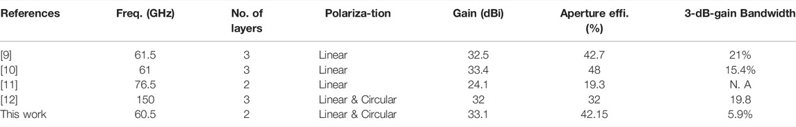
TABLE 2. Comparison of the proposed antenna with existing designs.
5 Conclusion
A double-layer complementary transmitarray structure is studied at 60 GHz for linear and circular polarizations. Combining the cross and slot-type structure, a double-layer frequency-selective element has been designed with good transmission phase and magnitude performances. The working principle of this complementary structure has been investigated and a prototype has been fabricated for verification. The measured antenna gain is 33.1 dB at 60.5 GHz with an aperture efficiency of 42.15%. The antenna structural complexity and cost have been reduced effectively. With these favorable advantages, this double-layer transmitarray antenna should have broad application prospects in the future.
Data Availability Statement
The raw data supporting the conclusion of this article will be made available by the authors, without undue reservation.
Author Contributions
WA prepared the idea and the original manuscript. XZ conducted the simulation and measurement, YL provided the instruction. LX provided and optimized. JW provided the fabrication and final manuscript.
Funding
This work was supported in part by National Natural Science Foundation of China (Grant no. 61701339), in part by National Natural Science Foundation of China for Key Project Grant no. 61831017).
Conflict of Interest
The authors declare that the research was conducted in the absence of any commercial or financial relationships that could be construed as a potential conflict of interest.
Publisher’s Note
All claims expressed in this article are solely those of the authors and do not necessarily represent those of their affiliated organizations, or those of the publisher, the editors and the reviewers. Any product that may be evaluated in this article, or claim that may be made by its manufacturer, is not guaranteed or endorsed by the publisher.
References
1. Abdelrahman AH, Nayeri P, Elsherbeni AZ, Yang F. Bandwidth Improvement Methods of Transmitarray Antennas. IEEE Trans Antennas Propagat (2015) 63(7):2946–54. doi:10.1109/tap.2015.2423706
2. Aziz A, Yang F, Xu S, Li M. An Efficient Dual-Band Orthogonally Polarized Transmitarray Design Using Three-Dipole Elements. IEEE Antennas Wireless Propag Lett (2018) 17(2):1452–7. doi:10.1109/lawp.2017.2788412
3. Rahmati B, Hassani HR. Low-profile Slot Transmitarray Antenna. IEEE Trans Antennas Propag (2015) 63(1):178–80. doi:10.1109/tap.2014.2368576
4. Hou Y, Chang L, Li Y, Zhang Z, Feng Z. Linear Multibeam Transmitarray Based on the Sliding Aperture Technique. IEEE Trans Antennas Propagat (2018) 66(8):3948–58. doi:10.1109/tap.2018.2835506
5. Nicholls JG, Hum SV. Full-space Electronic Beam-Steering Transmitarray with Integrated Leaky-Wave Feed. IEEE Trans Antennas Propag (2016) 64(4):3410–22. doi:10.1109/tap.2016.2576502
6. Xu K-D, Weng X, Li J, Guo Y-J, Wu R, Cui J, et al. 60-GHz Third-Order On-Chip Bandpass Filter Using GaAs pHEMT Technology. Semicond Sci Technol (2022) 2022. doi:10.1088/1361-6641/ac5bf8
7. Xu K-D, Guo Y-J, Liu Y, Deng X, Chen Q, Ma Z. 60-GHz Compact Dual-Mode On-Chip Bandpass Filter Using GaAs Technology. IEEE Electron Device Lett (2021) 42(8):1120–3. doi:10.1109/led.2021.3091277
8. Xu K-D, Xia S, Jiang Y, Guo Y-J, Liu Y, Wu R, et al. Compact Millimeter-Wave On-Chip Dual-Band Bandpass Filter in 0.15-μm GaAs Technology. IEEE J Electron Devices Soc (2022) 10:152–6. doi:10.1109/jeds.2022.3143999
9. Jouanlanne C, Clemente A, Huchard M, Keignart J, Barbier C, Le Nadan T, et al. Wideband Linearly-Polarized Transmitarray Antenna for 60 GHz Backhauling. IEEE Trans Antennas Propag (2017) 65(3):1440–5. doi:10.1109/TAP.2017.2655018
10. Dussopt L, Moknache A, Säily J, Lamminen A, Kaunisto M, Aurinsalo J, et al. A V-Band Switched-Beam Linearly Polarized Transmit-Array Antenna for Wireless Backhaul Applications. IEEE Trans Antennas Propagat (2017) 65(12):6788–93. doi:10.1109/tap.2017.2723921
11. Yeap SB, Qing X, Chen ZN. 77-GHz Dual-Layer Transmit-Array for Automotive Radar Applications. IEEE Trans Antennas Propagat (2015) 63(6):2833–7. doi:10.1109/tap.2015.2419691
12. Saleh W, Letestu Y, Sauleau R, Cruz EM. Design and Measurements of a High-Performance Wideband Transmitarray Antenna for D-Band Communications. Antennas Wirel Propag Lett (2021) 20(9):1765–9. doi:10.1109/lawp.2021.3096743
13. Abdelrahman AH, Elsherbeni AZ, Yang F. Transmission Phase Limit of Multilayer Frequency-Selective Surfaces for Transmitarray Designs. IEEE Trans Antennas Propagat (2014) 62(2):690–7. doi:10.1109/tap.2013.2289313
14. An W, Xu S, Yang F, Li M. A Double-Layer Transmitarray Antenna Using Malta Crosses with Vias. IEEE Trans Antennas Propag (2016) 64(3):1120–5. doi:10.1109/TAP.2015.2513427
15. Yang F, An W, Xu S, Li M. Double-layer Planar Phase Modulation Device. U.S. patent no. US10193232B2 (2019).
16. Yi X, Su T, Li X, Wu B, Yang L. A Double-Layer Wideband Transmitarray Antenna Using Two Degrees of freedom Elements Around 20 GHz. IEEE Trans Antennas Propagat (2019) 67(4):2798–802. doi:10.1109/tap.2019.2893265
17. Cai M-B, Yan Z-H, Fan F-F, Yang S-Y, Li X. Double-Layer 45° Linearly Polarized Wideband and Highly Efficient Transmitarray Antenna. IEEE Open J Antennas Propag (2021) 2:104–9. doi:10.1109/ojap.2020.3046474
18. Yang S, Yan Z, Cai M, Fan F, Zhang T. A High-Efficiency Double-Layer Transmitarray Antenna Using Low-Loss Dual-Linearly Polarized Elements. Antennas Wirel Propag Lett (2020) 19(12):2378–82. doi:10.1109/lawp.2020.3033460
19. Hu W, Dong J, Luo Q, Cai Y, Liu X, Wen L, et al. A Wideband Metal-Only Transmitarray with Two-Layer Configuration. Antennas Wirel Propag Lett (2021) 20(7):1347–51. doi:10.1109/lawp.2021.3081445
20. Li H, Wang G, Liang J, Gao X, Hou H, Jia X. Single-layer Focusing Gradient Metasurface for Ultrathin Planar Lens Antenna Application. IEEE Trans Antennas Propag (2017) 65(3):1452–7. doi:10.1109/TAP.2016.2642832
21. Zhang X, Yang F, Xu S, Aziz A, Li M. Dual-layer Transmitarray Antenna with High Transmission Efficiency. IEEE Trans Antennas Propagat (2020) 68(8):6003–12. doi:10.1109/tap.2020.2989555
22. Song L-Z, Qin P-Y, Guo YJ. A High-Efficiency Conformal Transmitarray Antenna Employing Dual-Layer Ultrathin Huygens Element. IEEE Trans Antennas Propagat (2021) 69(2):848–58. doi:10.1109/tap.2020.3016157
23. An W, Hong L, Li S. A Double-Layer Transmitarray Element Based on Complementary FSS Structure. In: Proceedings of the 2018 Cross Strait Quad-Regional Radio Science and Wireless Technology Conference; September 2018; Xuzhou, China (2018). p. 1–2.
24. Nayeri P, Elsherbeni AZ, Yang F. Radiation Analysis Approaches for Reflectarray Antennas [Antenna Designer's Notebook]. IEEE Antennas Propag Mag (2013) 55(1):127–34. doi:10.1109/map.2013.6474499
Keywords: high gain, double-layer, transmitarray, antenna, millimeter (MM) wave
Citation: An W, Zhang X, Luo Y, Wang J and Xiong L (2022) 60-GHz Double-Layer Transmitarray Antenna Using Complementary Structure. Front. Phys. 10:883686. doi: 10.3389/fphy.2022.883686
Received: 25 February 2022; Accepted: 18 March 2022;
Published: 06 April 2022.
Edited by:
Kai-Da Xu, Xi’an Jiaotong University, ChinaReviewed by:
Huanhuan Yang, Air Force Engineering University, ChinaZihao Chen, Harbin Institute of Technology, China
Copyright © 2022 An, Zhang, Luo, Wang and Xiong. This is an open-access article distributed under the terms of the Creative Commons Attribution License (CC BY). The use, distribution or reproduction in other forums is permitted, provided the original author(s) and the copyright owner(s) are credited and that the original publication in this journal is cited, in accordance with accepted academic practice. No use, distribution or reproduction is permitted which does not comply with these terms.
*Correspondence: Yu Luo, yluo@tju.edu.cn; Jian Wang, wangjian16@tju.edu.cn