- School of Physics and Optoelectronic Engineering, Yangtze University, Jingzhou, China
A scheme for the coherent control of perfect optical vortex (POV) in an asymmetric semiconductor double quantum well (SDQW) nanostructure is proposed by exploiting the tunneling-induced highly efficient four-wave mixing (FWM). The orbital angular momentum (OAM) is completely transferred from a unique POV mode to the generated FWM field. Using experimentally achievable parameters, we identify the conditions under which resonant tunneling allows us to improve the quality of the vortex FWM field and engineer helical phase wave front beyond what is achievable in the absence of resonant tunneling. Furthermore, we find that the intensity and phase patterns of the vortex FWM field are sensitive to the detuning of the probe field but rather robust against the detuning of the coupling field. Subsequently, we perform the coaxial interference between the vortex FWM field and a same-frequency POV beam and show interesting interference properties, which allow us to measure the topological charge of the output POV beam. Our result may find potential applications in quantum technologies based on POV in solids.
1 Introduction
In the past several decades, the study of optical vortices has been one of the hot spots in optics due to their potential applications in particle manipulation [1, 2], optical communication [3, 4], and quantum information processing [5–16]. Note that an optical vortex beam with a helical phase factor eilθ carries OAM of lℏ per photon, where l and θ are the topological charge (TC) and azimuthal angle, respectively [17–19]. Conventional optical vortex beams such as Laguerre–Gaussian (LG) beam [20], Bessel–Gauss (BG) beam [21], and high-order Bessel beam [22] exhibit the concentric ring intensity pattern at the transverse distribution. However, the ring radii of this kind of optical vortices is proportional to TCs, which make them face difficulties in actual applications requiring a small vortex diameter and a large topological charge [3] or spatial superposition of vortex beams with different TCs [4]. In order to overcome this challenge, Ostrovsky et al. first proposed the concept of the POV beam, whose ring radius is completely independent of its TC [23]. Since then, significant efforts have been made to explore the generation and detection of the POV beam [24–28]. For instance, different kinds of POV beams have been experimentally generated via using spatial light modulator [28, 29], polymer-based phase plate [30], strongly scattering media [31], single-layer dielectric metasurface [32], etc. In situ measurements for TC of POV beams have been realized via exploiting the phase shift method [33], optical modal decomposition [34], and hybrid angular gradient phase grating [35]. Quite recently, Dai et al put forward a scheme for the fractional OAM conversion of an asymmetric POV beam by using second-harmonic generation [31].
On the other hand, based on the combination of electromagnetically induced transparency (EIT) and standing waves, spatially dependent light-matter interaction has led to many interesting quantum optical phenomena such as atom localization [36, 37], electromagnetically induced grating [38], and controllable photonic band gaps [39]. In 2015, Radwell et al experimentally observed spatially dependent electromagnetically induced transparency via utilizing optical vortex beams to drive cold rubidium atoms [40]. Subsequently, numerous schemes for the spatially dependent light-matter interaction induced by LG beams have been proposed in cold atomic ensembles [41], rare-earth–doped crystal [42], two-dimensional array of metal-coated dielectric nanosphere [43], semiconductor quantum dots [44], and molecular magnets [45]. Meanwhile, many intriguing quantum optical phenomena have been discovered such as vortex-induced spatial absorption [46, 47], spatially structured Kerr nonlinearity [39], ultraprecise Rydberg atomic localization [48], vortex four-wave mixing (FWM) [44, 45, 49, 50, 51, 52], and spatially dependent hyper Raman scattering [53]. Recently, semiconductor quantum wells (SQWs) have been exploited to explore the transfer and control of mid-infrared LG beams due to their inherent advantages such as high nonlinear optical coefficient and large electric dipole moments of intersubband transitions [54, 55, 56]. As far as we know, no reports have been proposed for the investigation of the conversion and manipulation of a POV beam in SDQWs.
In this study, we investigate the conversion and manipulation of a POV beam in an asymmetric SDQW nanostructure via resonant tunneling. The OAM of a unique POV mode can be completely transferred to the generated FWM field via the tunneling-induced highly efficient FWM process. Differing from previous studies in solids [44, 54, 55, 56], the distinguishing features of this scheme are given as follows: First and foremost, we are interested in showing the conversion and manipulation of the mid-infrared perfect optical vortex (POV) beam, which has different vortex characteristics from LG beams in Refs. [54, 55, 56]. Second, our scheme combines the advantages of the four-level ladder-type scheme [55] and tunneling-induced constructive interference [57, 58]. With resonant tunneling, the FWM field is closer to an ideal POV beam, which is a significant advantage of our scheme compared with Ref. [55]. Third, the detunings of probe and coupling fields have different influences on the intensity and phase of the FWM field. Differing from previous schemes [54, 55, 56], the vortex properties of the FWM field are rather robust against the detuning of the strong continuous-wave (CW) coupling field. Furthermore, we show the coaxial interference between the vortex FWM field and a same-frequency POV beam and focus on the influence of the TC of the vortex FWM field on the interference pattern. The interference results illustrate that the interference intensity and phase patterns are determined by the TC of the FWM field, which allows us to measure the TC of the generated POV field.
2 Models and Equations
As shown in Figure 1A, we consider an n-doped asymmetric SDQW nanostructure, which can be grown by molecular-beam epitaxy (MBE) on a semi-insulating GaAs substrate [59]. After a buffer layer, the active region shown in Figure 1A is grown. It consists of a 118 Å wide deep well layer (GaAs) and a 130 Å wider shallow well layer (Al0.10Ga0.90As). The two well layers are separated by a 32 Å wide thin potential barrier (Al0.485Ga0.515As). Then, the growth is finished with a thick capping layer. The corresponding electron wave functions are shown via color-coded solid lines, and the energy levels are shown via blue dashed lines. The electron motion in the z-direction is limited by the potential barrier of the SDQW and obeys the one-dimensional effective mass Schr
where
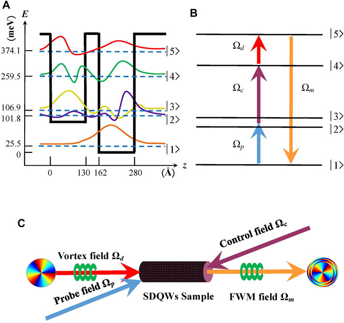
FIGURE 1. (A,B) Schematic of diagram of an asymmetric SDQW nanostructure with five subbands. The solid curves represent the schematics of the corresponding electronic wave functions. (C) A simple block diagram of the SDQW nanostructure sample with four optical fields, in which the driving field is a POV beam.
In the interaction picture and under the rotating-wave approximation, the Hamiltonian of this system is given by:
where
Defining the electronic energy state as
where γi (i = 2, 3, 4, 5) is added phenomenologically to describe the overall decay rate of the subbands |i⟩, (i = 2, 3, 4, 5). In order to simplify the calculation, we assume the phase matching condition, that is,
The following Maxwell equations describe the propagation equations of the probe and FWM fields:
where ζp = ζ21(31) = 2Nωp|μ21(31)|2/(ℏɛ0c), ζm = ζ51 = 2Nωm|μ51|2/(ℏɛ0c) are two constants, which are related to the frequently used oscillator strengths of the subband transitions |1⟩ ↔ |2 (3)⟩ and |1⟩ ↔ |5⟩. N is the electron sheet density. The transverse derivatives
In the limit of the weak probe and FWM fields, most of the electrons remain in the subband |1⟩, that is, |A1|2 ≈ 1. Taking Fourier transform of Eqs 3–6 and 7, 8, we obtain
where d2 = ω + Δp + iγ2, d3 = ω + Δp − δ + iγ3, d4 = ω + Δp + Δc + iγ4, d5 = ω + Δm + iγ5, ω is the Fourier variable.
where Dp1 = Dp1(ω), Dp2 = Dp2(ω), Dm1 = Dm1(ω), Dm2 = Dm2(ω), D = D(ω), Dp1(ω) = d5 (α − β)2|Ωc|2 − (d2α2 + d3) (d4d5 − |Ωd|2), Dp2(ω) = −(d2αβ + d3)ΩcΩd,
By substituting Eqs 15, 16 into Eqs 13, 14 and using the initial condition
where
where K± = K±(0), η± = t − z/Vg±, and
with
It is worth noting that the modulation term S, which is independent of the propagation distance L, can also influence the output of the FWM field, that is, the modulation term S appears once the FWM process takes place. Thus, S is the inherent attribute for the SDQW-based FWM system. S is a complex function of the radial position r due to the existence of the POV driving field and can modify the intensity and phase patterns of the generated FWM field. In order to compare with the modal phase shift Re(K+) and modal absorption Im (K+), we introduce a factor Q to replace S by setting S = eiQL = ei Re(Q)L− Im(Q)L. In this sense, the inherent phase shift and absorption induced by S can be represented by Re(Q) and Im(Q). Thus, Re(Q) and Im(Q) are called as the inherent phase shift per unit length and absorption coefficient of the SDQW-based FWM system. Using K+ = Re(K+) + i Im (K+), Eq. 19 can be rewritten as
where the intensity of the vortex FWM field is
3 Results and Discussions
In this section, the focus is on investigating the coherent control of the generated POV beam via FWM process in an asymmetric SDQW nanostructure. As we know, the structure of a SQW determines its properties such as resonant tunneling and subband decay rates. In other words, these properties of the SQW are determined once it is fabricated. Thus, the values of the decay rates may be different for the cases with and without resonant tunneling. In the proposed asymmetric SDQW nanostructure, resonant tunneling exists, that is, α = −0.11, β = 0.98, and δ = 5.1 meV, and the decay rates are γ2 = γ3 = 1 meV and γ4 = γ5 = 0.1 meV [58]. For comparative analysis, we consider the case without resonant tunneling by directly taking α = β = 0 and δ = 0. This approach has been used to investigate tunneling-induced highly efficient FWM [57,58].
The influence of the resonant tunneling on the intensity and phase of the generated FWM field is explored first. Here, the driving field Ωd (r, θ) is a POV beam with the TC l = 3, and the corresponding intensity and phase profiles are plotted in Figures 2A,D, respectively. The intensity distribution of the driving field in Figure 2A exhibits a ring pattern at the radial position r = 2 mm with a full width at half maximum (FWHM) of ΔωH = 0.402 mm. Meanwhile, the helical phase profile in Figure 2D displays three periods along the azimuthal direction, and the phase of each period is 2π. Based on Eq. 21, the intensity and phase profiles of the generated FWM field are also plotted in Figure 2. As shown in Figures 2B,E, in the absence of resonant tunneling, that is, α = β = 0 and δ = 0, the intensity distribution also displays a ring pattern at r = 2 mm with an increased FWHM of ΔωH = 0.606 mm (see Figure 2B), while the helical phase twists in the clockwise direction [see Figure 2E]. When considering the existence of resonant tunneling, that is, α = −0.11, β = 0.98 and δ = 5.1 meV [58], as shown in Figures 2C,F, the intensity of the vortex FWM field is almost unchanged, and FWHM of the intensity pattern decreases from 0.606 to 0.384 mm, while the helical phase twists in the opposite direction compared with the case in Figures 2B,E. More interestingly, the phase distortion is significantly enhanced at two edges of the intensity pattern. For a POV beam, the FWHM of the intensity pattern can be adopted in appraising the quality of POV, where ΔωH = 0 corresponds to an ideal POV beam [23]. The direct comparison between the aforementioned two cases implies that the resonant tunneling makes the generated vortex FWM field closer to an ideal POV beam and modifies the wave front of the helical phase. Actually, the resonant tunneling can lead to the symmetric and asymmetric wave functions of subbands |2⟩ and |3⟩ in the SDQW nanostructure (i.e., αβ < 0). Therefore, the optical nonlinear properties of the SDQW nanostructure can be modified by the resonant tunneling, which results in the different findings in Figure 2.
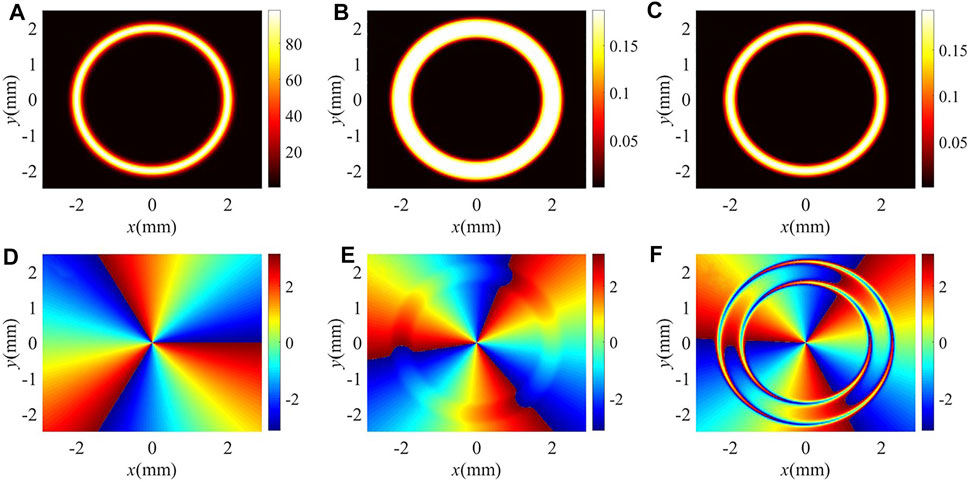
FIGURE 2. (A,D) Intensity and phase profiles of the drive field with POV. (B,C) Intensity and (E,F) phase profiles of the FWM field for different values of α, β, and δ: (B,E) α = β = 0, δ = 0 meV; (C,F) α = −0.11, β = 0.98, δ = 5.1 meV. The other parameters are ζp = ζm = 9.2 × 10⁻³ meV/μm, L = 100 μm, l = 3, wg = 200 μm, λ = 10.83 μm, R = 2 mm, f = 11.69 mm, Ωp = 1 meV, Ωc = 14 meV, Ωd0 = 10 meV, Δp = 16 meV, and Δc = Δm = 0 meV.
In order to inspect the effect of the resonant tunneling, the radial distributions of the imaginary and real parts of Q and K+ are plotted in Figure 3. Note that the inherent absorption Im(Q) and modal absorption Im (K+) at r = 2 mm determine the output intensity of the vortex FWM field. Without and with resonant tunneling, the total absorption coefficients at r = 2 mm are 57.77 μm−1 and 57.56 μm−1, respectively. In the two cases, the total absorption coefficients are nearly equal so that the intensity of the FWM field remains nearly constant. In addition, the inherent absorption Im(Q) and modal absorption Im (K+) determine the intensity distribution of the generated vortex FWM field, while the inherent phase shift Re(Q) and modal phase shift Re(K+) determine the wave front distribution of the helical phase. Without the resonant tunneling, the inherent absorption Im(Q) dominates in tailoring the intensity profile of the FWM field [see blue lines in Figures 3A,C]. The ring pattern of the FWM field becomes flat in the vortex transfer processing due to the existence of the strong inherent absorption peak at r = 2 mm. Thus, the FWHM of the vortex FWM field increases compared with the driving field with POV. The appearance of peaks of both the inherent and modal phase shifts at r = 2 mm results in the helical phase twisted in the clockwise direction (see red lines in Figures 3A,C). With the resonant tunneling, the FWM field suffers stronger inherent and modal absorption at two edges of the intensity pattern (see blue lines in Figures 3B,D). In this case, the edge energy of the vortex FWM field can be easily dissipated, resulting in the width of the intensity pattern becoming narrower. The double-valley pattern of the dominated modal phase shift around r = 2 mm gives rise to two tremendous distortions in the anticlockwise direction (see red lines in Figures 3B,D).
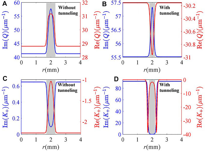
FIGURE 3. Real and imaginary parts of (A,B) Q and (C,D) K+ versus radius r for different values of α, β, and δ: (A,C) α = β = 0, δ = 0 meV; (B,D) α = −0.11, β = 0.98, δ = 5.1 meV. Other parameters are the same as in Figure 2.
We then examine in Figure 4 the influence of the detuning Δp of the probe field on the intensity and helical phase of the vortex FWM field in the presence of the resonant tunneling. The corresponding radial distributions of the imaginary and real parts of Q and K+ are shown in Figure 5. One can find that the total absorption (including inherent and modal absorption) at the center of the light ring increases when increasing Δp from −4 to 8 meV (see blue lines in Figure 5). Correspondingly, the intensity of the vortex FWM field decreases (see Figures 4A–C). In the case of Δp = −4 meV, one can find from Figures 4A,D that the FWHM of the light ring is wide (ΔωH = 0.416 mm) while the distortion of the helical phase is almost invisible. The reason is that the vortex FWM field suffers a strong inherent absorption at the center of the light ring and a small total phase shift (including inherent and modal phase shifts) (Figures 5A,D). When the probe detuning is varied from −4 to 4 meV, the vortex FWM field suffers stronger inherent and modal absorption at the edges of the intensity pattern (see Figure 5B), and there are single peaks of inherent phase shift and double peaks of modal phase shift (Figure 5E). Therefore, the FWHM of the intensity pattern decreases to 0.196 mm (Figure 4B), and the helical phase twists in the clockwise direction (Figure 4E). More importantly, the twisted helical phase wave front is flat because of complementation between inherent and modal phase shifts. As the probe detuning increases to 8 meV, as shown in Figures 4C,F, 5C,F, the FWHM of the intensity slightly increases to 0.264 mm due to the wider transparent window in modal absorption spectrum. Meanwhile, the helical phase twists anticlockwise because of the existence of a single valley of inherent phase shift and double valleys of modal phase shift. Therefore, one can conclude that the detuning of the probe field can manipulate the helical phase wave front of the generated FWM field in an effective manner.
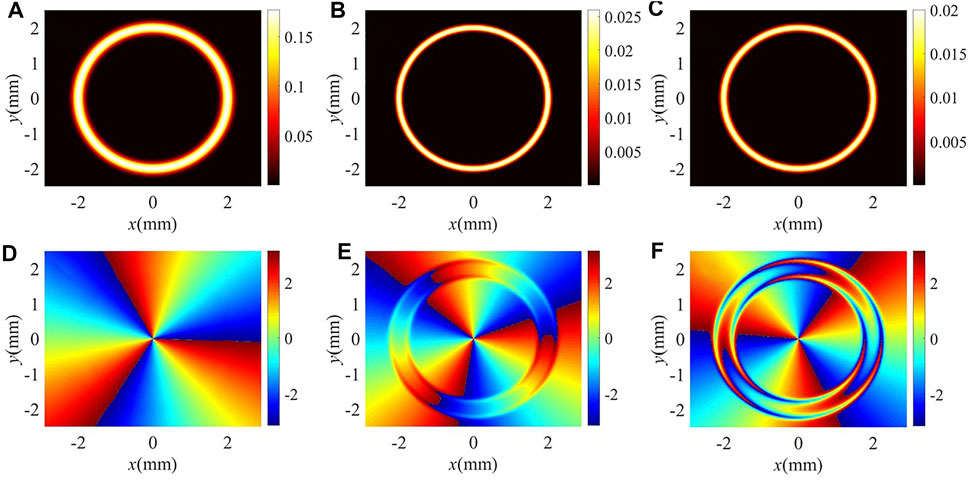
FIGURE 4. (A–C) Intensity and (D–F) phase profiles of the FWM field for different probe detuning Δp: (A,D) Δp = −4 meV; (B,E) Δp = 4 meV; (C,F) Δp = 8 meV. Other parameters are the same as in Figure 2C.
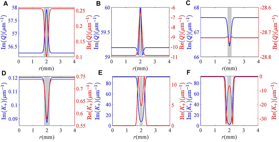
FIGURE 5. Real and imaginary parts of (A–C) Q and (D–F) K+ versus radius r for different probe detuning Δp: (A,D) Δp = −4 meV; (B,E) Δp = 4 meV; (C,F) Δp = 8 meV. Other parameters are the same as in Figure 2C.
We further investigate the dependence of the intensity and helical phase of the vortex FWM field on the detuning Δc of the coupling field in Figures 6, 7. It can be seen from Figure 6 that the intensity, width, and phase of the vortex FWM field are not very sensitive to the coupling detuning Δc. The results can be explained that the impact of the coupling detuning on the absorption and phase properties of the FWM field is weak. At the center of the light ring, the modal absorption remains unchanged and the inherent absorption decreases slowly with the increase of Δc (see blue lines in Figure 7), so we can find that the intensity of the vortex FWM field increases limitedly in Figures 6A–C. However, the FWHM of the intensity pattern is kept at 0.216 mm because of the strong inherent and modal absorption at the two edges of the intensity pattern. At the same time, the modal phase shift dominates in modulating the helical phase wave front of the FWM field (see red lines in Figure 7). As shown in Figures 6D–F, the near-identical double valleys of the modal phase shift result in almost the same double distortions for the helical phase wave front. Therefore, the generated vortex FWM field has good robustness on the detuning of the coupling field.
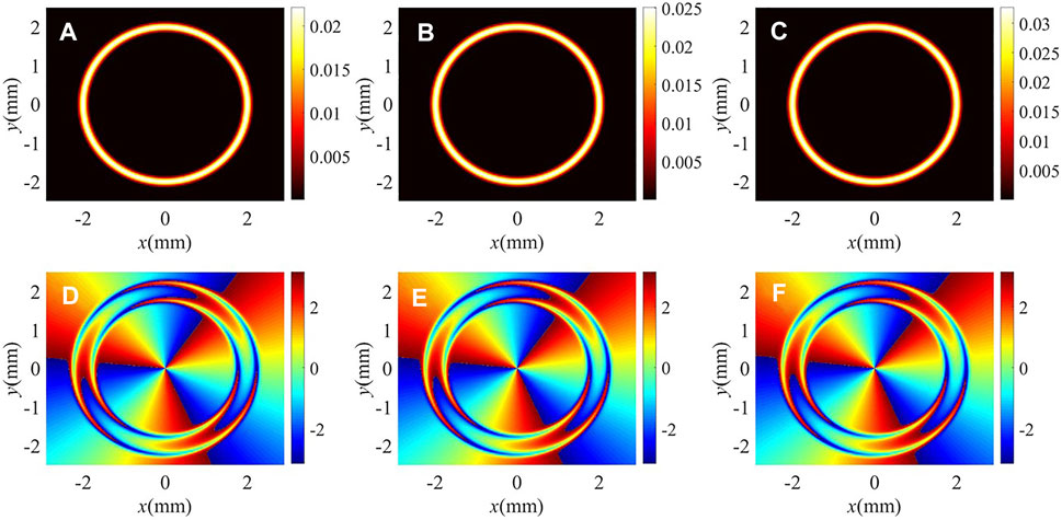
FIGURE 6. (A–C) Intensity and (D–F) phase profiles of the FWM field for different coupling detuning Δc: (A,D) Δc = 4 meV; (B,E) Δc = 8 meV; (C,F) Δc = 16 meV. Other parameters are the same as in Figure 4C.
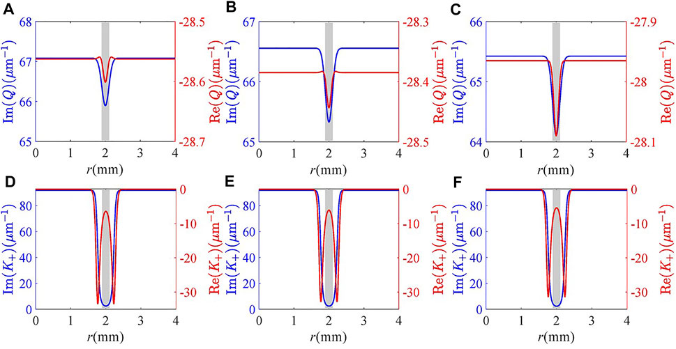
FIGURE 7. Real and imaginary parts of (A–C) Q and (D–F) K+ versus radius r for different coupling detuning Δc: (A,D) Δc = 4 meV; (B,E) Δc = 8 meV; (C,F) Δc = 16 meV. Other parameters are the same as in Figure 4C.
Now, we analyze the influence of the conventional LG beam and POV beam with higher order TC on the intensity and phase patterns of the vortex FWM field in Figure 8. In the former case, we select the traditional single-ring LG beam
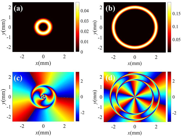
FIGURE 8. (A,B) Intensity and (C,D) phase profiles of the FWM field for different beams. (A,C) LG beam with p = 0, l = 3, and wLG = 0.5 mm; (B,D) POV beam with l = 6. Other parameters are the same as in Figure 2C.
We note that, very recently, some theoretical schemes for exploring the vortex FWM process in SQWs have been proposed [54, 55, 56]. In these schemes, SQWs were used to explore the transfer and control of mid-infrared conventional LG beams [54, 55] and inner–outer ring LG beams [56]. In comparison with these schemes, the major differences in our proposal are the following: First, the main difference between our scheme and Refs. [54, 55, 56] is that we focus on the conversion and manipulation of the mid-infrared POV beam, while previous studies are focused on the control of the mid-infrared LG beams. Second, our scheme takes the advantages of the four-level ladder-type scheme [55] and tunneling-induced constructive interference [57, 58]. For example, resonant tunneling can effectively open the channel for the FWM process and modify the spatial distribution of the FWM field. Third, with the presence of resonant tunneling, both the intensity and phase patterns are insensitive to the detuning of the coupling field. The findings are quite different from the results obtained in Ref. [55], where the intensity pattern and phase distortion strongly depend on the detuning of the corresponding field.
Finally, we perform the coaxial interference between the vortex FWM field and a same-frequency POV beam
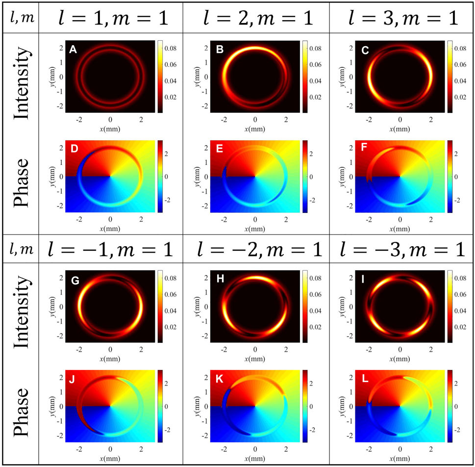
FIGURE 9. Interference intensity [(A–C) and (G–I)] and phase [(D–F) and (J–L)] profiles of different values of TC of the FWM field. ΩG0 = 0.16 meV, m = 1, and other parameters are the same as in Figure 4C.
4 Conclusion
We mainly focus on the condition of low temperatures up to 10 K, and have neglected other many-body effects such as the depolarization effect, which renormalizes the free-carrier and carrier-field contributions. These contributions and their interplay have been investigated quite thoroughly in Ref. [60]. Note that due to the low electron sheet density considered here, these effects only give a negligible correction.
In conclusion, a scheme for transferring and manipulating POV in an asymmetric SDQW nanostructure is theoretically suggested. The OAM of a unique POV mode is completely transferred to the generated FWM field via a tunneling-induced highly efficient FWM process. It is demonstrated that resonant tunneling plays an important role in the manipulation of the intensity and phase distribution of the vortex FWM field. With the presence of resonant tunneling, the generated FWM field is closer to an ideal POV beam and exhibits an enhanced phase distortion at two edges of the intensity pattern. Furthermore, we find that the intensity and phase profiles of the vortex FWM field are sensitive to the detuning of the weak probe field but rather robust against the detuning of the strong coupling field. These results can be reasonably explained via the combination of inherent and modal dispersion relation. Subsequently, the coaxial interference between the vortex FWM field and a same-frequency POV beam is studied. It is found that the interference intensity and phase patterns are determined by TC of the vortex FWM field, which allows us to measure TC of the FWM field with POV. Our proposal may provide an avenue for the coherent control of POV and a possibility for the TC measurement of a POV beam.
Data Availability Statement
The raw data supporting the conclusion of this article will be made available by the authors, without undue reservation.
Author Contributions
The idea was first conceived by W-XY. XD was responsible for the physical model, numerical calculations, and writing most of the manuscript. TS contributed to writing the manuscript and verified the calculated results.
Funding
The National Natural Science Foundation of China (11774054, 12075036, 12104067); the Science and Technology Research Project of Education Department of Hubei Province (Q20211314).
Conflict of Interest
The authors declare that the research was conducted in the absence of any commercial or financial relationships that could be construed as a potential conflict of interest.
Publisher’s Note
All claims expressed in this article are solely those of the authors and do not necessarily represent those of their affiliated organizations or those of the publisher, the editors, and the reviewers. Any product that may be evaluated in this article, or claim that may be made by its manufacturer, is not guaranteed or endorsed by the publisher.
Acknowledgments
XD thanks Chun Meng, Yi Song, and Tong Zhang for helpful discussions.
References
1. Arita Y, Chen M, Wright EM, Dholakia K. Dynamics of a Levitated Microparticle in Vacuum Trapped by a Perfect Vortex Beam: Three-Dimensional Motion Around a Complex Optical Potential. J Opt Soc Am B (2017) 34:C14–C19. doi:10.1364/josab.34.000c14
2. Liang Y, Lei M, Yan S, Li M, Cai Y, Wang Z, et al. Rotating of Low-Refractive-index Microparticles with a Quasi-Perfect Optical Vortex. Appl Opt (2018) 57:79–84. doi:10.1364/AO.57.000079
3. Yan H, Zhang E, Zhao B, Duan K. Free-space Propagation of Guided Optical Vortices Excited in an Annular Core Fiber. Opt Express (2012) 20:17904–15. doi:10.1364/OE.20.017904
4. Li S, Wang J. Multi-orbital-angular-momentum Multi-Ring Fiber for High-Density Space-Division Multiplexing. IEEE Photon J (2013) 5:7101007. doi:10.1109/jphot.2013.2272778
5. Leach J, Jack B, Romero J, Jha A, Yao A, Franke-Arnold S, et al. Quantum Correlations in Optical Angle-Orbital Angular Momentum Variables. Science (2010) 329:662–5. doi:10.1126/science.1190523
6. Fickler R, Lapkiewicz R, Plick W, Krenn M, Schaeff C, Ramelow S, et al. Quantum Entanglement of High Angular Momenta. Science (2012) 338:640–3. doi:10.1126/science.1227193
7. Ding D, Zhou Z, Shi B, Guo G. Single-photon-level Quantum Image Memory Based on Cold Atomic Ensembles. Nat Commun (2013) 4:2527. doi:10.1038/ncomms3527
8. Nicolas A, Veissier L, Giner L, Giacobino E, Maxein D, Laurat J. Quantum Memory for Orbital Angular Momentum Photonic Qubits. Nat Photon (2014) 8:234–8. doi:10.1038/nphoton.2013.355
9. Parigi V, D’Ambrosio V, Arnold C, Marrucci L, Sciarrino F, Laurat J. Storage and Retrieval of Vector Beams of Light in a Multiple-Degree-Of-freedom Quantum Memory. Nat Commun (2015) 6:706. doi:10.1038/ncomms8706
10. Wang X, Luo Y, Huang H, Chen M, Su Z, Liu C, et al. 18-qubit Entanglement with Six Photons’ Three Degrees of freedom. Phys Rev Lett (2018) 120:260502. doi:10.1103/PhysRevLett.120.260502
11. Luo Y, Zhong H, Erhard M, Wang X, Peng L, Krenn M, et al. Quantum Teleportation in High Dimensions. Phys Rev Lett (2019) 123:070505. doi:10.1103/PhysRevLett.123.070505
12. Pan X, Yu S, Zhou Y, Zhang K, Zhang K, Lv S, et al. Orbital-angular-momentum Multiplexed Continuous-Variable Entanglement from Four-Wave Mixing in Hot Atomic Vapor. Phys Rev Lett (2019) 123:070506. doi:10.1103/PhysRevLett.123.070506
13. Zhang S, Zhou Y, Mei Y, Liao K, Wen Y, Li J, et al. δ-Quench Measurement of a Pure Quantum-State Wave Function. Phys Rev Lett (2019) 123:190402. doi:10.1103/PhysRevLett.123.190402
14. Li S, Pan X, Ren Y, Liu H, Yu S, Jing J. Deterministic Generation of Orbital-Angular-Momentum Multiplexed Tripartite Entanglement. Phys Rev Lett (2020) 124:083605. doi:10.1103/PhysRevLett.124.083605
15. Zhang K, Wang W, Liu S, Pan X, Du J, Lou Y, et al. Reconfigurable Hexapartite Entanglement by Spatially Multiplexed Four-Wave Mixing Processes. Phys Rev Lett (2020) 124:090501. doi:10.1103/PhysRevLett.124.090501
16. Liu S, Lou Y, Jing J. Orbital Angular Momentum Multiplexed Deterministic All-Optical Quantum Teleportation. Nat Commun (2020) 11:3875. doi:10.1038/s41467-020-17616-4
17. Allen L, Beijersbergen MW, Spreeuw RJC, Woerdman JP. Orbital Angular Momentum of Light and the Transformation of Laguerre-Gaussian Laser Modes. Phys Rev A (1992) 45:8185–9. doi:10.1103/physreva.45.8185
18. Padgett M, Courtial J, Allen L. Light’s Orbital Angular Momentum. Phys Today (2004) 57:35–40. doi:10.1063/1.1768672
19. Molina-Terriza G, Torres J, Torner L. Twisted Photons. Nat Phys (2007) 3:305–10. doi:10.1038/nphys607
20. Allen L, Padgett MJ, Babiker M. Iv the Orbital Angular Momentum of Light. Prog Opt (1999) 39:291–372. doi:10.1016/S0079-6638(08)70391-3
21. Gori F, Guattari G, Padovani C. Bessel-gauss Beams. Opt Commun (1987) 64:491–5. doi:10.1016/0030-4018(87)90276-8
22. Sepulveda K, Chávez V, Cerda S, Arlt J, Dholakia K. Orbital Angular Momentum of a High-Order Bessel Light Beam. J Opt B Quan Semiclass. Opt (2002) 4:S82. doi:10.1088/1464-4266/4/2/373
23. Ostrovsky A, Rickenstorff-Parrao C, Arrizón V. Generation of the “Perfect” Optical Vortex Using a Liquid-crystal Spatial Light Modulator. Opt Lett (2013) 38:534–6. doi:10.1364/OL.38.000534
24. Kotlyar V, Kovalev A, Porfirev A. Optimal Phase Element for Generating a Perfect Optical Vortex. J Opt Soc Am (2016) 33:2376–84. doi:10.1364/JOSAA.33.002376
25. Karahroudi M, Parmoon B, Qasemi M, Mobashery A, Saghafifar H. Generation of Perfect Optical Vortices Using a Bessel-Gaussian Beam Diffracted by Curved fork Grating. Appl Opt (2017) 56:5817–23. doi:10.1364/AO.56.005817
26. Jabir M, Chaitanya NA, Aadhi A, Samanta G. Generation of “Perfect” Vortex of Variable Size and its Effect in Angular Spectrum of the Down-Converted Photons. Sci Rep (2016) 6:21977. doi:10.1038/srep21877
27. Garcia-Garcia J, Rickenstorff-Parrao C, Ramos-Garcia R, Arrizon V, Ostrovsky A. Simple Technique for Generating the Perfect Optical Vortex. Opt Lett (2014) 39:5305–8. doi:10.1364/OL.39.005305
28. Vaity P, Rusch L. Perfect Vortex Beam: Fourier Transformation of a Bessel Beam. Opt Lett (2015) 40:597–600. doi:10.1364/OL.40.000597
29. Du Y, Liu D, Fu S, Wang Y, Qin Y. Reconfigurable Generation of Double-Ring Perfect Vortex Beam. Opt Express (2021) 29:17353–64. doi:10.1364/OE.424664
30. Guo Z, Liu H, Xiang L, Chen L, Yang J, Wen J, et al. Generation of Perfect V Ortex Beams with Polymer-Based Phase Plate. IEEE Photon Technol Lett (2020) 32:565–8. doi:10.1109/LPT.2020.2985745
31. Dai K, Miller J, Li W, Watkins R, Johnson E. Fractional Orbital Angular Momentum Conversion in Second-Harmonic Generation with an Asymmetric Perfect Vortex Beam. Opt Lett (2021) 46:3332–5. doi:10.1364/OL.428859
32. Zhou Q, Liu M, Zhu W, Chen L, Ren Y, Lezec H, et al. Generation of Perfect Vortex Beams by Dielectric Geometric Metasurface for Visible Light. Laser Photon Rev (2021) 15:2100390. doi:10.1002/lpor.202100390
33. Ma H, Li X, Tai Y, Li H, Wang J, Tang M, et al. In Situ measurement of the Topological Charge of a Perfect Vortex Using the Phase Shift Method. Opt Lett (2017) 42:135–8. doi:10.1364/OL.42.000135
34. Pinnell J, Rodríguez-Fajardo V, Forbes A. Quantitative Orbital Angular Momentum Measurement of Perfect Vortex Beams. Opt Lett (2019) 44:2736–9. doi:10.1364/ol.44.002736
35. Chu C, Gao S, Liu Z, Tu J, Yang J, Hao C, et al. Hybrid Angular Gradient Phase Grating for Measuring the Orbital Angular Momentum of Perfect Optical Vortex Beams. IEEE Photon J (2020) 12:1. doi:10.1109/jphot.2020.2986266
36. Jiang X, Li J, Sun X. Two-dimensional Atom Localization Based on Coherent Field Controlling in a Five-Level M-type Atomic System. Opt Express (2017) 25:31678–87. doi:10.1364/OE.25.031678
37. Tian Y, Wang X, Yang W, Shui T, Li L, Li X, et al. High-precision Three Dimensional Atom Localization via Multiphoton Quantum Destructive Interference. Opt Express (2020) 28:25308–18. doi:10.1364/OE.396973
38. Zhou F, Qi Y, Sun H, Chen D, Yang J, Niu Y, et al. Electromagnetically Induced Grating in Asymmetric Quantum wells via Fano Interference. Opt Express (2013) 21:12249–59. doi:10.1364/oe.21.012249
39. Che J, Zhao P, Ma D, Zhang Y. Kerr-nonlinearity-modulated Dressed Vortex Four-Wave Mixing from Photonic Band gap. Opt Express (2020) 28:18343–50. doi:10.1364/oe.395426
40. Radwell N, Clark T, Piccirillo B, Barnett S, Franke-Arnold S. Spatially Dependent Electromagnetically Induced Transparency. Phys Rev Lett (2015) 114:123603. doi:10.1103/PhysRevLett.114.123603
41. Han L, Cao M, Liu R, Liu H, Guo W, Wei D, et al. Identifying the Orbital Angular Momentum of Light Based on Atomic Ensembles. EPL (2012) 99:34003. doi:10.1209/0295-5075/99/34003
42. Wang L, Zhang X, Li A, Kang Z, Wang H, Gao J. Controlled-Not Gate with Orbital Angular Momentum in a Rare-Earth-Ion-Doped Solid. J Lumin (2020) 228:117628. doi:10.1016/j.jlumin.2020.117628
43. Hamedi H, Yannopapas V, Paspalakis E. Spatially Structured Optical Effects in a Four-Level Quantum System Near a Plasmonic Nanostructure. Ann Phys (2021) 533:2100117. doi:10.1002/andp.202100117
44. Rahmatullah, , Abbas M, Ziauddin, , Qamar S. Spatially Structured Transparency and Transfer of Optical Vortices via Four-Wave Mixing in a Quantum-Dot Nanostructure. Phys Rev A (2020) 101:023821. doi:10.1103/PhysRevA.101.023821
45. Mahdavi M, Sabegh Z, Hamedi H, Mahmoudi M. Orbital Angular Momentum Transfer in Molecular Magnets. Phys Rev B (2021) 104:094432. doi:10.1103/PhysRevB.104.094432
46. Hamedi H, Kudriasov V, Ruseckas J, Juzeliunas G. Azimuthal Modulation of Electromagnetically Induced Transparency Using Structured Light. Opt Express (2018) 26:28249–62. doi:10.1364/OE.26.028249
47. Dai X, Hao X, Jin R, Peng C, Ding C. Controllable Probe Absorption Spectrum via Vortex Beams Excitation in a Cascaded Atomic System. J Appl Phys (2021) 129:224303. doi:10.1063/5.0050488
48. Jia N, Qian J, Kirova T, Juzeliunas G, Hamedi H. Ultraprecise Rydberg Atomic Localization Using Optical Vortices. Opt Express (2020) 28:36936–52. doi:10.1364/OE.411130
49. Yu C, Wang Z. Engineering Helical Phase via Four-Wave Mixing in the Ultraslow Propagation Regime. Phys Rev A (2021) 103:013518. doi:10.1103/PhysRevA.103.013518
50. Qiu J, Wang Z, Ding D, Huang Z, Yu B. Control of Space-dependent Four-Wave Mixing in a Four-Level Atomic System. Phys Rev A (2020) 102:033516. doi:10.1103/PhysRevA.102.033516
51. Hamedi H, Ruseckas J, Juzeliūnas G. Exchange of Optical Vortices Using an Electromagnetically-Induced-Transparency–Based Four-Wave-Mixing Setup. Phys Rev A (2018) 98:013840. $\\bar{\\mathrm{u}}$. doi:10.1103/physreva.98.013840
52. Hong Y, Wang Z, Ding D, Yu B. Ultraslow Vortex Four-Wave Mixing via Multiphoton Quantum Interference. Opt Express (2019) 27:29863–74. doi:10.1364/OE.27.029863
53. Chen J, Wang Z, Yu B. Spatially Dependent Hyper-Raman Scattering in Five-Level Cold Atoms. Opt Express (2021) 29:10914–22. doi:10.1364/oe.420015
54. Qiu J, Wang Z, Ding D, Li W, Yu B. Highly Efficient Vortex Four-Wave Mixing in Asymmetric Semiconductor Quantum wells. Opt Express (2020) 28:2975–86. doi:10.1364/OE.379245
55. Zhang Y, Wang Z, Qiu J, Hong Y, Yu B. Spatially Dependent Four-Wave Mixing in Semiconductor Quantum wells. Appl Phys Lett (2019) 115:171905. doi:10.1063/1.5121275
56. Wang Z, Zhang Y, Paspalakis E, Yu B. Efficient Spatiotemporal-Vortex Four-Wave Mixing in a Semiconductor Nanostructure. Phys Rev A (2020) 102:063509. doi:10.1103/PhysRevA.102.063509
57. Sun H, Fan S, Zhang H, Gong S. Tunneling-induced High-Efficiency Four-Wave Mixing in Asymmetric Quantum wells. Phys Rev B (2013) 87:235310. doi:10.1103/PhysRevB.87.235310
58. Sun D, Zhang H, Sun H, Li X, Li H. Tunneling-induced Highly Efficient Four-Wave Mixing in Asymmetric Double Quantum wells. Laser Phys Lett (2018) 15:045208. doi:10.1088/1612-202X/aaa9c8
59. Schmidt H, Campman K, Gossard A, Imamolu A. Tunneling Induced Transparency: Fano Interference in Intersubband Transitions. Appl Phys Lett (1997) 70:3455–7. doi:10.1063/1.119199
Keywords: perfect optical vortex, coherent control, resonant tunneling, four-wave mixing, quantum well
Citation: Deng X, Shui T and Yang W-X (2022) Coherent Control of Perfect Optical Vortex Through Four-Wave Mixing in an Asymmetric Semiconductor Double Quantum Well. Front. Phys. 10:877859. doi: 10.3389/fphy.2022.877859
Received: 17 February 2022; Accepted: 16 March 2022;
Published: 19 April 2022.
Edited by:
Guangling Cheng, East China Jiaotong University, ChinaReviewed by:
Yandong Peng, Shandong University of Science and Technology, ChinaChunling Ding, Wuhan Institute of Technology, China
Copyright © 2022 Deng, Shui and Yang. This is an open-access article distributed under the terms of the Creative Commons Attribution License (CC BY). The use, distribution or reproduction in other forums is permitted, provided the original author(s) and the copyright owner(s) are credited and that the original publication in this journal is cited, in accordance with accepted academic practice. No use, distribution or reproduction is permitted which does not comply with these terms.
*Correspondence: Tao Shui, YWh1c2h1aXRhb0AxMjYuY29t; Wen-Xing Yang, d2VueGluZ3lhbmcyQDEyNi5jb20=
 Xu Deng
 Tao Shui
 Wen-Xing Yang