- Key Laboratory of Conveyance and Equipment, Ministry of Education, East China Jiaotong University, Nanchang, China
In the transmission process of gear system, the change of load will make the system in different states of motion, which affects the transmission efficiency of gear system. It is important to investigate the nonlinear dynamic characteristics of gear system under different load states. Using straight cylindrical gears as the object of study, the concentrated mass method is used to establish a dynamic model that takes into account nonlinear factors such as tooth side clearance, time-varying meshing stiffness and transmission errors. The differential equations of the system are solved by the Longe-Kutta method to obtain the bifurcation diagram, the maximum Lyapunov exponent diagram and the phase plane diagram of the gear system to analyze the effect of the meshing damping ratio on the dynamic characteristics of the system under different load states. The results show that the influence of the engagement damping ratio on the dynamic characteristics of the system is greater under light load conditions, showing different states of motion as the engagement damping ratio gradually increases. Under heavy load conditions, the effect of the engagement damping ratio on the dynamic characteristics of the system is small. Appropriately increasing the mesh damping ratio is beneficial to the gear system to avoid the chaotic zone and maintain a stable cyclic motion state. The results of the study provide a reference for the design of gear systems with variable loads.
Introduction
As one of the most commonly used forms of mechanical transmission, gear systems are used in a large number of applications in various fields because of their constant power and smooth speed. Gear systems are subjected to complex and variable loads during work engineering, and different loads can lead to the existence of unstable motion in the system, and can even lead to an increase in transmission errors and noise as well as the decay of gear life. Therefore, the study of the dynamic behavior of the gear system under different load states and the analysis of the influence law of each parameter on the stability of the system can effectively improve the working condition of the gear and prolong the working life.
In order to study the nonlinear dynamics of gear systems in depth, many scholars have introduced new methods and theories to investigate the generation and influencing factors of the nonlinear dynamics behavior of gear systems. Chen et al [1] established a gear model for single tooth deformation, optimized the tooth side clearance, and provided theoretical guidance for the selection of gear dynamics models. Cai et al [2] proposed a generalized nonlinear dynamics model based on Lagrange Bond diagrams and verified the validity of the model through relevant experiments. Chen et al [3] proposed a model including tooth surface morphology parameters and verified the validity of the Section model through a series of simulations. Chen et al [4] developed an improved model based on the redefined gap equation, and the validity of the model was verified by theoretical and experimental data. Atanasiu et al [5] established an improved meshing stiffness model by introducing specific meshing characteristics of helical gear pairs, and numerically analyzed the model to obtain the variation law of dynamic transmission errors. Lai et al [6, 7] propose a new chaotic system and illustrate the bifurcation and chaotic properties of the system by numerical analysis. Wang et al [8] verified the effectiveness and feasibility of removing chaos through feedback and non-feedback control methods. Lai et al [9] designed a controller based on the passive control method, which is able to maintain the stability of the system when it is used. In addition, many other scholars have modeled and analyzed gear systems in different devices. Huang et al [10, 11] modeled the dynamics for micro-segment gear pairs and analyzed the effect of different parameters on the dynamic characteristics of the system using numerical analysis. Srikanth et al [12] developed a dynamic model based on wind turbine drive train considering bearing stiffness and torsional shaft stiffness, and solved the coupled dynamic model to obtain the time and frequency domain response of the drive train. Chen Sheng et al [13, 14] developed a gear dynamics model for the coal mining machine drive system and analyzed the effect of temperature as well as other nonlinear parameters on the stability of the system, respectively. Yang et al [15] analyzed the effect of different trim parameters on the dynamic characteristics of the system for cycloidal cam gears. Several scholars have developed gear dynamics models considering various nonlinear factors and analyzed the nonlinear dynamical behavior of gear systems with different parameter variations by different solving methods [16–19]. Li et al [20] developed a gear model considering the nonlinear effects of both gears and bearings, and verified the dynamics of the model by numerical simulation calculations. Wang et al [21, 22] developed a torsional model of a coupled gear-rotor drive system and analyzed various nonlinear dynamic characteristics of the system by means of global bifurcation and other methods. Hortel et al [23] analyzed the effect of all parameter variables on the internal dynamics of a nonlinear system with time-varying damping. Many scholars have developed different models to study the effect of friction and engagement damping ratios on the dynamic characteristics of the system by numerical analysis methods [24–27].
From the literature, it can be seen that scholars at home and abroad have conducted a lot of research on the dynamic characteristics, but there is less research on the dynamics bifurcation and chaos of the transmission system under different load states. When the gear system is in different load states, it will show different motion characteristics. When the motion characteristics of the gear system are in the chaotic zone, it will cause serious impact on the system noise, operation reliability, and even lead to gear destruction. Therefore, it is necessary to carry out a detailed study of the dynamics of the gear system under different loads.
In this paper, a gear system dynamics model considering tooth side clearance, time-varying meshing stiffness and transmission error is developed using the concentrated mass method. The stability of the system is analyzed by solving the differential equations of motion of the system by the Lundgren-Kutta method and obtaining bifurcation diagrams, maximum Lyapunov exponent diagrams and phase plane diagrams to study the bifurcation and chaotic characteristics of the gear system under different load conditions. The results of the analysis can provide a theoretical reference for the design of gear systems with variable loads.
Dynamics Modeling
Due to the influence of many non-linear factors, the vibration of the gear system is complicated and presents a non-linear vibration condition. Therefore, to analyze the nonlinear kinematic characteristics of the gear system, it is necessary to consider the effects of nonlinear factors such as tooth side clearance, integrated errors and time-varying meshing stiffness, and to establish an overall vibration analysis model from the system as a whole by using the concentrated mass method.
Gear Dynamics Modeling
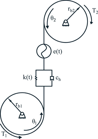
The gearing system operates with a concentrated mass as a whole, so the concentrated mass method can be used to model the nonlinear dynamics of the gearing system. The following assumptions need to be made when modeling: the gears have only torsional motion during operation; the frictional influence of the support bearings is not considered; and the direction of the gear meshing force is always acting on the meshing line. Then the dynamics model of a pair of involute gear pairs is represented as shown in the Figure 1.
According to the kinetic model, the set of differential equations of motion can be deduced using Newton’s law as:
Where k(t) is the time-varying meshing stiffness; ch is the meshing damping coefficient; e(t) is the gear meshing error;
Gear Meshing Stiffness
When the gear meshes, its meshing stiffness is not constant but is constantly changing with time, this change is the time-varying stiffness, the excitation phenomenon caused by it is called gear stiffness excitation.
Since gearing is a periodic motion, the meshing stiffness is a periodic function with certain laws. When the same gear pair is meshed, the frequency of stiffness change is the same as the frequency of internal excitation, so the meshing stiffness can be expressed in the form of Fourier series:
Where, km refers to the average meshing stiffness; ωh refers to the meshing frequency of the gear; kj refers to the amplitude of the meshing stiffness.
Now taking the first-order harmonic component of the stiffness, the time-varying meshing stiffness is:
Tooth Side Gap
Tooth side clearance is caused by manufacturing and assembly and is a strong nonlinear factor in dynamics studies. During the motion of the gear pair, the meshing trajectory changes continuously due to the tooth-side clearance, which affects the gear meshing accuracy and life under repeated loads. Therefore, it is necessary to consider the effect of tooth side clearance when studying the dynamic characteristics of gear systems.
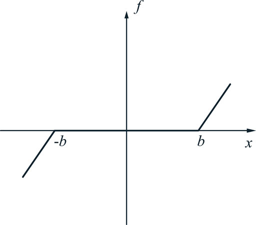
The gear side clearance function is a non-linear meshing force displacement function of the gear when there is side clearance, as a segmented function. Assuming a side gap of 2b, the segmentation function f (x(t)) can be expressed as [28]:
If the gap is symmetric, then
Gear Meshing Error
When the actual meshing position of the gear profile deviates from the ideal position, displacement excitation, also called error excitation, is formed.
The error of a gear varies periodically as it meshes, so for analysis, a Fourier series expansion of the gear meshing frequency can be performed as follows [29]:
Where, em is the average error; ej is the harmonic component of the error amplitude.
Since the static transmission error is small, only the first-order harmonic components are considered for ease of analysis. Taking em = 0 when considering only the first order, the first-order harmonic component of the meshing error is:
Define the displacements of the two gears along the meshing line as x1 and x2, and x1 represents the active wheel displacement and x2 represents the driven wheel displacement. Then it is obtained that:
The dynamic transmission error of the gear system is
Then the difference between the dynamic transmission error and the static transmission error of the system, i.e., the combined transmission error, is:
Dynamical Model Dimensionless Processing
Dividing equations in Eq. 1 by rb1 and rb2, respectively, and substituting Eq. 7 to simplify gives:
Where: mi (i = 1,2) are the equivalent masses of the master and driven wheels, expressed as
In order to eliminate the effect of stiffness displacement, the transmission error of Eq. 9 is substituted into Eq. 10 to organize the following:
Where: me is the equivalent mass of the gear;
Substituting Eqs 3, 13 into Eq. 11 yields:
To facilitate the computational study of the dynamical properties of gear systems, the dynamical differential equations need to be dimensionless. Assume that the inherent frequency of the gear system model is:
Defining the quantization time as
From this, the dimensionless analytical model of the differential equations of the dynamics model of the gear system can be derived as follows.
Nonlinear Dynamics Characterization
The load state to which the gear system is subjected has a large influence on its dynamics, so it is necessary to study the dynamics of the gear system under light and heavy load conditions. The load state is expressed as the ratio of the external moment load Fm to the error amplitude Fh. The larger the ratio, the greater the load on the gear system. Therefore, when Fm takes a fixed value, the value of Fh is inversely proportional to the load, so when Fh = 0.1, the gear system is in heavy load; when Fh = 0.3, the gear system is in light load. The remaining system parameters take the following values: The average load Fm = 0.1; the time-varying meshing stiffness coefficient s = 0.1; the tooth side clearance b = 0.5; the dimensionless frequency
In this paper, the dynamics equations of the gear system are solved numerically by the Lundgren-Kutta method. Based on the steady-state response, the bifurcation diagram, the maximum Lyapunov exponent diagram and the phase diagram are used as analytical tools to study the dynamics of the gear system under light and heavy load conditions, respectively.
Effect of Damping Ratio on System Characteristics Under Light Load Condition
When the gear system is under light load, the relevant parameters are taken as follows: error amplitude Fh = 0.3; average load Fm = 0.1; time-varying meshing stiffness coefficient s = 0.1; tooth side clearance b = 0.5; dimensionless frequency
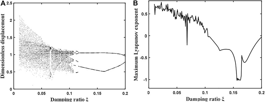
FIGURE 3. (A) Bifurcation diagram of the system with the variation of damping ratio under light load condition. (B) Plot of the maximum Lyapunov index.
By observing Figure 3, it can be found that with the gradual increase of the damping ratio, the gear system first shows a complex chaotic motion until the damping ratio is 0.11, then the system enters the proposed periodic motion, and then enters a short 4 times the proposed periodic motion, and the damping ratio continues to increase, the gear system enters a stable 2 times the periodic motion. Therefore, when the mesh damping ratio gradually increases from 0.01 to 0.2, the overall gear system undergoes a change of “chaotic motion—2 times anthropomorphic periodic motion—4 times anthropomorphic periodic motion—2 times anthropomorphic periodic motion”, and its corresponding maximum Lyapunov exponent graph also undergoes an overall change of “positive—zero—negative".
When the damping factor ξ = 0.05, the dynamics of the gear system is shown in Figure 4, the time domain diagram has no obvious periodicity, the phase plane diagram does not repeat and fills a closed area, the frequency spectrum is a continuous frequency band, and the Poincare section diagram consists of patches of dense points, so the system is in a complex chaotic motion at this time. When the damping factor ξ = 0.11, the dynamics of the gear system is shown in Figure 5, and its time domain diagram has regular peaks and presents a certain periodicity, the phase diagram is presented as a closed curve band, the spectrum diagram is discrete, and the Poincare section diagram is composed of 2 point sets, so the system is in a 2-fold proposed periodic motion at this time.
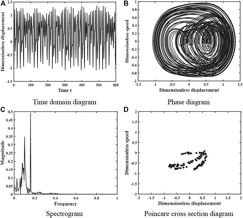
FIGURE 4. Dynamics of the gear system at ξ = 0.05 under light load (A) Time domain diagram. (B) Phase diagram. (C) Spectrogram. (D) Poincare cross section diagram.
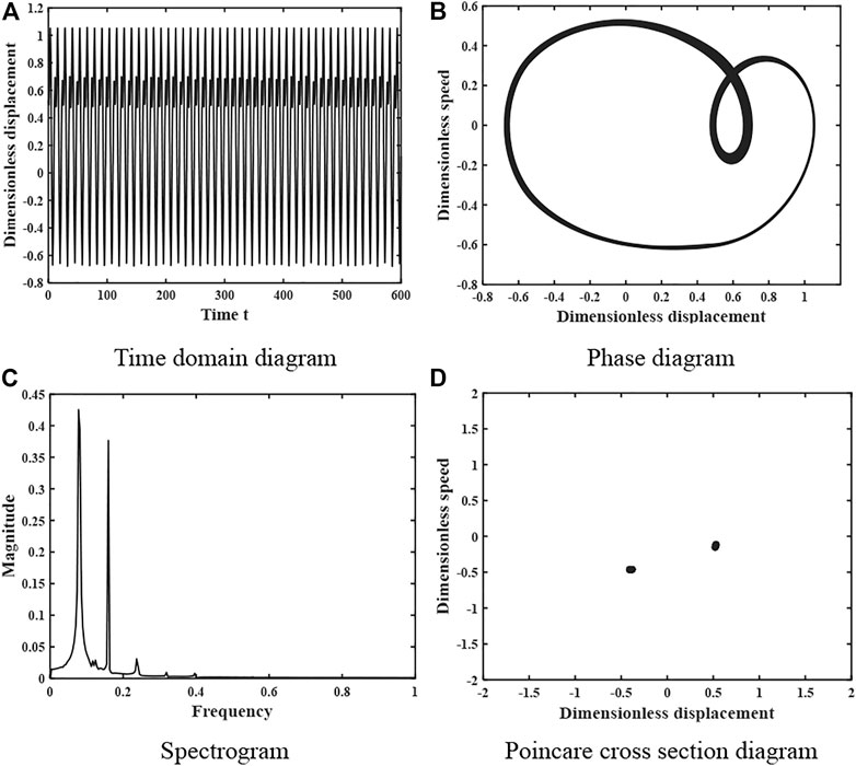
FIGURE 5. Dynamics of the gear system at ξ = 0.11 under light load (A) Time domain diagram. (B) Phase diagram. (C) Spectrogram. (D) Poincare cross section diagram.
When the damping factor ξ = 0.113, the dynamics of the gear system is shown in Figure 6, whose time domain diagram is a periodic curve with regular peaks, the phase diagram shows a closed curve, the spectrum diagram is discrete, and the Poincare cross-sectional diagram consists of several point sets and the number of point sets is 4. Therefore, the system is in a 4-fold proposed periodic motion at this time. When the damping factor ξ = 0.16, the motion characteristics of the gear system are shown in Figure 7. The time domain diagram has certain periodicity and the peak value remains stable, the phase diagram shows a closed curve, the spectrum diagram is discrete, and the Poincare section diagram consists of 2 points, so the system is in a 2-fold periodic motion at this time.
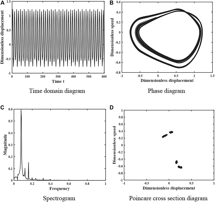
FIGURE 6. Dynamics of the gear system at ξ = 0.113 under light load (A) Time domain diagram. (B) Phase diagram. (C) Spectrogram. (D) Poincare cross section diagram.
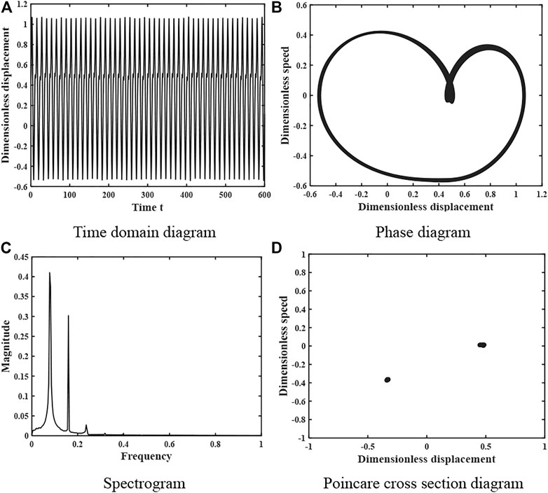
FIGURE 7. Dynamics of the gear system at ξ = 0.16 under light load (A) Time domain diagram. (B) Phase diagram. (C) Spectrogram. (D) Poincare cross section diagram.
The kinematic characteristics of the system presented in Figures 4–7 are consistent with the overall kinematic characteristics that vary with the damping ratio shown in Figure 3.
The results show that the variation of the damping ratio coefficient has a large effect on the nonlinear dynamic characteristics of the system when the gear system is under light load. Therefore, when analyzing and verifying the gear system under light load, the stability of the system can be enhanced by increasing the damping ratio coefficient to avoid the chaotic motion.
Effect of Damping Ratio on System Characteristics Under Heavy Load
When the gear system is under heavy load, the relevant parameters of the system are taken as follows: error amplitude Fh = 0.1; average load Fm = 0.1; time-varying meshing stiffness coefficient s = 0.1; tooth side clearance b = 0.5; dimensionless frequency
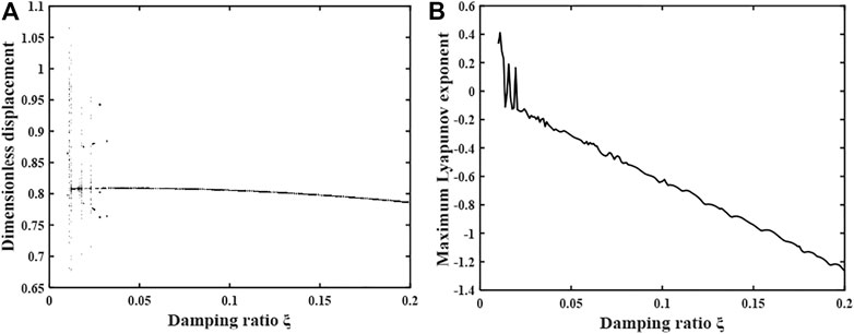
FIGURE 8. (A) Bifurcation diagram of the system with the variation of damping ratio under heavy load condition. (B) Plot of the maximum Lyapunov index.
By observing Figure 8, it can be found that with the gradual increase of the damping ratio, the gear system first enters a brief chaotic motion state, followed by alternating single-fold periodic motion and chaotic motion states. Until the damping ratio increases to 0.028, the system enters into a brief triple anthropomorphic periodic motion, and as the damping ratio continues to increase, the system changes to a single periodic motion state and remains stable. The maximum Lyapunov exponent undergoes a general change of “positive-zero-negative-zero-positive-zero-negative”, which is consistent with the change of motion shown in the bifurcation diagram.
When the damping ratio ξ = 0.01, the motion characteristics of the gear system are shown in Figure 9, the time domain diagram has no obvious periodicity, the peak is not regular, the phase plane diagram does not repeat and fills a closed area, the spectrum diagram is a continuous curve, and the Poincare section diagram is composed of a piece of dense points, so the system is in a complex chaotic motion state at this time. When the damping ratio coefficient increases to ξ = 0.021, the motion characteristics of the system are shown in Figure 10, the time domain diagram shows obvious periodicity and the peak has regularity, the phase diagram is a closed curve band, the spectrum diagram is a discrete curve, and the Poincare section diagram consists of 1 point, so the system is in a single periodic motion at this time.
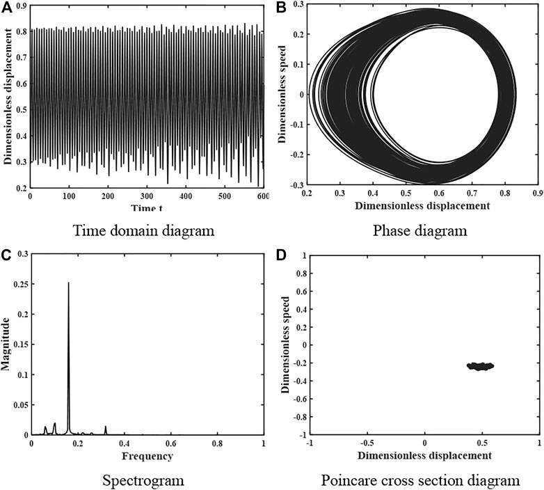
FIGURE 9. Dynamics of the gear system at ξ = 0.01 under heavy load (A) Time domain diagram. (B) Phase diagram. (C) Spectrogram. (D) Poincare cross section diagram.
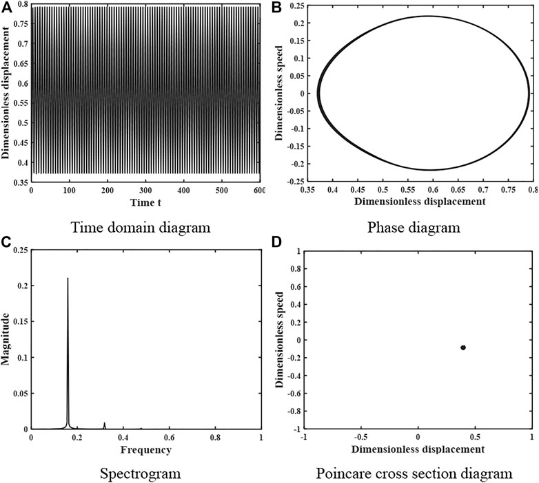
FIGURE 10. Dynamics of gear system at heavy load condition ξ = 0.021 (A) Time domain diagram. (B) Phase diagram. (C) Spectrogram. (D) Poincare cross section diagram.
When the damping ratio coefficient continues to increase to ξ = 0.032, the motion characteristics of the system are shown in Figure 11. The time domain diagram is a periodic curve with peak law, the phase diagram is a closed circular curve, the spectrum diagram is a curve with three peaks, and the Poincare cross-sectional diagram consists of three point sets, so the system is in a 3-fold proposed periodic motion at this time. When the damping ratio coefficient ξ = 0.16, the motion characteristics of the system are shown in Figure 12. The time domain diagram shows an obvious periodicity, and the peak is kept stable, the phase diagram is a closed curve, the spectrum diagram is a discrete curve with a single peak, and the Poincare cross-section diagram consists of a single point, so the system is in a stable single-fold periodic motion at this time.
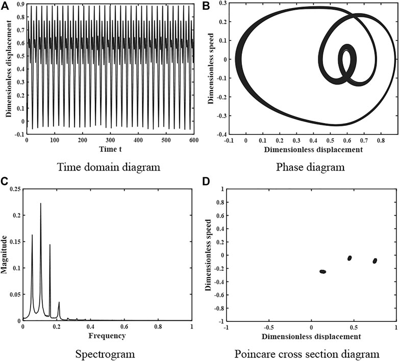
FIGURE 11. Dynamics of the gear system at ξ = 0.028 under heavy load. (A) Time domain diagram. (B) Phase diagram. (C) Spectrogram. (D) Poincare cross section diagram.
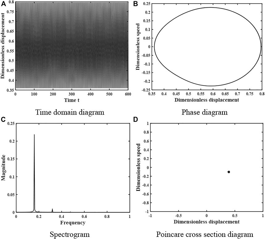
FIGURE 12. Dynamics of the gear system at ξ = 0.16 under heavy load. (A) Time domain diagram. (B) Phase diagram. (C) Spectrogram. (D) Poincare cross section diagram.
The changes in the kinematic state of the gear system shown in Figures 9–12 are consistent with the effect of the damping ratio coefficient ξ on the system stability obtained in Figure 8, verifying the accuracy of the analysis process and results.
The results show that the variation of the damping ratio coefficient of the gear system under heavy load condition has less effect on the stability of the system.
Conclusion
In this paper, a nonlinear dynamics model of the gear system is established, and the differential equations of the model are solved numerically using the Lundgren-Kutta method to obtain the nonlinear dynamics behavior and bifurcation chaos characteristics of the system. The stability of the system is analyzed by bifurcation diagram, maximum Lyapunov exponent diagram and phase plane diagram, and the following conclusions are obtained.
1) In the light load condition, the change of meshing damping ratio has a greater impact on the gear system. Under the premise of ensuring the transmission efficiency, the increase of the engagement damping ratio can make the system gradually change from the hybrid motion state to the proposed periodic and multi-cycle motion state. Therefore, the design and lubrication of the gear system under light load condition can significantly improve the nonlinear dynamic response of the system by appropriately increasing the meshing damping ratio of the system under the premise of ensuring the transmission efficiency.
2) Under heavy load conditions, the change in the engagement damping ratio has less effect on the system. The system alternates between chaotic and periodic motion states only when the engagement damping ratio is taken to be less than 0.04. As the damping ratio continues to increase, the system enters a single-fold periodic motion state and remains stable. Therefore, when designing and lubricating the heavy-duty gear system, a larger mesh damping ratio can be taken, which can make the system avoid the chaotic zone and be in a stable single cycle motion.
According to the research results, it is known that when designing the gear transmission system, it is suitable to adjust the meshing damping ratio, which can make the gear system move more smoothly. However, there are still some issues to be further thought and explored, for example, the gear system affects the gear transmission performance because of thermal deformation during operation, and the influence of temperature change should be considered when establishing the model; in addition, strong nonlinear factors affecting the gear system such as bearing lubrication should be considered.
Data Availability Statement
The original contributions presented in the study are included in the article/Supplementary Material, further inquiries can be directed to the corresponding author.
Author Contributions
JW, manuscript revisement; ZS, system analysis, draft written; SC, numerical analysis.
Funding
This research was supported by the National Natural Science Foundation of China (Grant No.51765020), and the Natural Science Foundation of Jiangxi Province (Grant No. 20161BAB206153).
Conflict of Interest
The authors declare that the research was conducted in the absence of any commercial or financial relationships that could be construed as a potential conflict of interest.
Publisher’s Note
All claims expressed in this article are solely those of the authors and do not necessarily represent those of their affiliated organizations, or those of the publisher, the editors and the reviewers. Any product that may be evaluated in this article, or claim that may be made by its manufacturer, is not guaranteed or endorsed by the publisher.
Acknowledgments
The authors would like to thank reviewers for their helpful comments and suggestions to improve the manuscript.
References
1. Chen Z, Ning J, Wang K, Zhai W. An Improved Dynamic Model of spur Gear Transmission Considering Coupling Effect between Gear Neighboring Teeth. Nonlinear Dyn (2021) 106(1):339–57. doi:10.1007/s11071-021-06852-y
2. Cai Z, Lin C. Dynamic Model and Analysis of Nonlinear Vibration Characteristic of a Curve-Face Gear Drive. SV-JME (2017) 63(3):161–70. doi:10.5545/sv-jme.2016.3859
3. Chen Q, Wang Y, Tian W, Wu Y, Chen Y. An Improved Nonlinear Dynamic Model of Gear Pair with Tooth Surface Microscopic Features. Nonlinear Dyn (2019) 96(2):1615–34. doi:10.1007/s11071-019-04874-1
4. Chen Q, Zhou J, Khushnood A, Wu Y, Zhang Y. Modelling and Nonlinear Dynamic Behavior of a Geared Rotor-Bearing System Using Tooth Surface Microscopic Features Based on Fractal Theory. Aip Adv (2019) 9(1):015201. doi:10.1063/1.5055907
5. Atanasiu V, Doroftei I, Iacob MR, Leohchi D. Nonlinear Dynamics of Steel/Plastic Gears of Servomechanism Structures. Materiale Plastice (2011) 48(1):98–103.
6. Lai Q, Wan Z, Kamdem Kuate PD. Modelling and Circuit Realisation of a New No‐equilibrium Chaotic System with Hidden Attractor and Coexisting Attractors. Electron Lett (2020) 56(20):1044–6. doi:10.1049/el.2020.1630
7. Lai Q, Wan Z, Kengne LK, Kamdem Kuate PD, Chen C. Two-Memristor-Based Chaotic System with Infinite Coexisting Attractors. IEEE Trans Circuits Syst (2021) 68(6):2197–201. doi:10.1109/tcsii.2020.3044096
8. Wang J, Wang H, Guo L. Analysis of Nonlinear Dynamics and Chaos Control in Gear Transmission System with Stochastic Perturbation. Mech (2017) 23(2):236–46. doi:10.5755/j01.mech.23.2.13576
9. Lai Q, Norouzi B, Liu F. Dynamic Analysis, Circuit Realization, Control Design and Image Encryption Application of an Extended Lü System with Coexisting Attractors. Chaos, Solitons & Fractals (2018) 114:230–45. doi:10.1016/j.chaos.2018.07.011
10. Xiong Y, Huang K. Bifurcation and Chaos Characteristic Analysis of spur Micro-segment Gear Pair. J Vibroeng (2016) 18(7):4792–811. doi:10.21595/jve.2016.17129
11. Huang K, Xu F, Xiong Y, Sang M, Yi Y. Nonlinear Dynamic Analysis of a Microsegment Gear System with a Time-Varying Base circle. Trans Can Soc Mech Eng (2020) 44(2):279–93. doi:10.1139/tcsme-2019-0086
12. Srikanth P, Sekhar A. Dynamic Analysis of Wind Turbine Drive Train Subjected to Nonstationary Wind Load Excitation. Proc Inst Mech Eng C: J Mech Eng Sci (2015) 229(3):429–46. doi:10.1177/0954406214536547
13. Chen J, Li W, Xin G, Sheng L, Jiang S, Li M. Nonlinear Dynamic Characteristics Analysis and Chaos Control of a Gear Transmission System in a Shearer under Temperature Effects. Proc Inst Mech Eng Part C: J Mech Eng Sci (2019) 233(16):5691–709. doi:10.1177/0954406219854112
14. Sheng L, Li W, Wang Y, Fan M, Yang X. Nonlinear Dynamic Analysis and Chaos Control of Multi-freedom Semi-direct Gear Drive System in Coal Cutters. Mech Syst Signal Process (2019) 116:62–77. doi:10.1016/j.ymssp.2018.06.043
15. Yang R, Han B, Xiang J. Nonlinear Dynamic Analysis of a Trochoid Cam Gear with the Tooth Profile Modification. Int J Precis Eng Manuf (2020) 21(12):2299–321. doi:10.1007/s12541-020-00417-6
16. Chen Y, Zhu RP, Xiong YP, Jin GH. Bifurcation and Chaotic Characteristics of Bevel Gears System Considering Multiple Dynamic Factors. J Vibration Eng Tech (2017) 5(5):467–76.
17. Li Y, Chen T, Wang X. Non-linear Dynamics of Gear Pair with Dynamic Backlash Subjected to Combined Internal and External Periodic Excitations. J Vibration Control (2016) 22(6):1693–703. doi:10.1177/1077546314544350
18. Xia Y, Wan Y, Liu Z. Bifurcation and Chaos Analysis for a spur Gear Pair System with Friction. J Braz Soc Mech Sci Eng (2018) 40(11):19. doi:10.1007/s40430-018-1443-7
19. Xiang L, Gao N, Hu A. Dynamic Analysis of a Planetary Gear System with Multiple Nonlinear Parameters. J Comput Appl Maths (2018) 327:325–40. doi:10.1016/j.cam.2017.06.021
20. Li Z, Peng Z. Nonlinear Dynamic Response of a Multi-Degree of freedom Gear System Dynamic Model Coupled with Tooth Surface Characters: a Case Study on Coal Cutters. Nonlinear Dyn (2016) 84(1):271–86. doi:10.1007/s11071-015-2475-5
21. Wang S, Zhu R. Nonlinear Torsional Dynamics of Star Gearing Transmission System of GTF Gearbox. Shock and Vibration (2020) 2020:1–15. doi:10.1155/2020/6206418
22. Wang J, Wang H, Wang H, Guo L. Influence of the Random System Parameters on the Nonlinear Dynamic Characteristics of Gear Transmission System. Int J Nonlinear Sci Numer Simulation (2017) 18(7-8):619–30. doi:10.1515/ijnsns-2016-0119
23. Hortel M, Škuderová A. Nonlinear Time Heteronymous Damping in Nonlinear Parametric Planetary Systems. Acta Mech (2014) 225(7):2059–73. doi:10.1007/s00707-013-1041-9
24. Hou J, Yang S, Li Q, Liu Y. Nonlinear Dynamic Analysis of spur Gear System Based on Fractional-Order Calculus. Mod Phys Lett B (2020) 34(36):2050420. doi:10.1142/s0217984920504205
25. Shi Z, Lim TC. Modeling of Impact Damping Effect on Hypoid Gear Dynamic Response. J Vibration Acoustics-Transactions Asme (2019) 141(6):14. doi:10.1115/1.4044658
26. Cui LL, Xu H, Shang DG, Xu YG. Study on Coupling Effect between the Time-Varying Gear Backlash and the Different Time-Varying Mesh Parameters on the Gear System. J Vibroeng (2017) 19(8):5874–91. doi:10.21595/jve.2017.18200
27. Yang Z, Shang J-z., Luo Z-r. Effect Analysis of Friction and Damping on Anti-backlash Gear Based on Dynamics Model with Time-Varying Mesh Stiffness. J Cent South Univ (2013) 20(12):3461–70. doi:10.1007/s11771-013-1870-7
28. Xiao Z, Jianwei L, Zuoyun W, Huimin X. Dynamic Modeling and Analysis on Gear Transmission System with Consideration of the Tooth Surface Friction and thermal Deformation. J Vibration Shock (2017) 36(10):207–231. doi:10.13465/j.cnki.jvs.2017.10.033
29. Wang J, He G, Zhang J, Zhao Y, Yao Y. Nonlinear Dynamics Analysis of the spur Gear System for Railway Locomotive. Mech Syst Signal Process (2017) 85:41. doi:10.1016/j.ymssp.2016.08.004
Keywords: nonlinear dynamics, bifurcation, chaos, engagement damping ratio, maximum lyapunov index
Citation: Wang J, Shan Z and Chen S (2022) Bifurcation and Chaos Analysis of Gear System With Clearance Under Different Load Conditions. Front. Phys. 10:838008. doi: 10.3389/fphy.2022.838008
Received: 17 December 2021; Accepted: 11 February 2022;
Published: 01 March 2022.
Edited by:
Xiao-Wen Zhao, Hefei University of Technology, ChinaReviewed by:
Qing Yun Wang, Beihang University, ChinaJinman He, Zhongyuan University of Technology, China
Copyright © 2022 Wang, Shan and Chen. This is an open-access article distributed under the terms of the Creative Commons Attribution License (CC BY). The use, distribution or reproduction in other forums is permitted, provided the original author(s) and the copyright owner(s) are credited and that the original publication in this journal is cited, in accordance with accepted academic practice. No use, distribution or reproduction is permitted which does not comply with these terms.
*Correspondence: Jungang Wang, bWV3amdAZWNqdHUuZWR1LmNu
 Jungang Wang
 Zheng’ang Shan