 Minqiang Liu
 Xianguo Xu*
95% of researchers rate our articles as excellent or good
Learn more about the work of our research integrity team to safeguard the quality of each article we publish.
Find out more
BRIEF RESEARCH REPORT article
Front. Phys. , 28 October 2022
Sec. Optics and Photonics
Volume 10 - 2022 | https://doi.org/10.3389/fphy.2022.1035846
This article is part of the Research Topic Physical Model and Applications of High-Efficiency Electro-Optical Conversion Devices, volume II View all 11 articles
The TID (total ionizing dose) in-situ experiments of LC1020B, an anti-fuse FPGA (Field Programmable Gate Array) device, were designed and carried out under different dose rates, and the influence of dose rate on the TID effect of FPGA was studied. The experimental results show that: 1) the TID irradiation failure of the FPGA under different dose rates has nothing to do with the input voltage parameter exceeding the standard. 2) with the decrease of cobalt source irradiation dose rate [171, 26.83, and 2.68 mGy(Si)/s], the TID effect failure dose threshold [168, 229, and 334 Gy(Si), respectively] of the FPGA gradually increased, showing obvious attenuation of low dose rate damage. Theoretical analysis suggests that, compared with the space charge limitation effect, the oxide charge annealing effect plays a dominant role, and longer irradiation time is beneficial to the oxide charge annealing. And based on the experimental data, an FPGA TID analytical model with power consumption current as the damage characterization parameter is established, which lays a foundation for scientific evaluation of radiation effect of anti-fuse FPGAs.
BECAUSE the electronic devices used in aerospace electronic system will be bombarded by high-energy particles when they work in the radiation environment, their working parameters and service life will inevitably be affected, and system failure or even accidents may be caused in serious cases [1, 2]. FPGA (Field Programmable Gate Array) has a wide application in satellite [3] and other aerospace fields [4] because of its high reliability, strong performance, good flexibility, low power consumption and short development cycle. During the early 1970s, radiation hardened CMOS integrated circuits began to be developed [5]. The international research on the TID effect of FPGA has been carried out in the 1990s [6], and a profound understanding of the test methods [7], sensitive parameters [8], failure law [9] and simulation model [10] of the TID effect of FPGA devices has been obtained. And a large number of experimental data on TID effect of FPGA have been accumulated [11].
Previous research shows that TID experimental results obtained by different researchers for samples of the same type differs from each other as a result of the different dose rates utilized, sometimes the difference is very great [12, 13]. Therefore, some researchers have carried out targeted studies about the influence of dose rate on the TID effect of MOS devices [14], analyzed the influence of dose rate on the sensitive electrical parameters of MOS devices [15], and found the damage enhancement effect of low dose rate [16]. However, for complex digital devices such as anti-fuse FPGA, there is still a lack of scientific understanding about the influence of dose rate on TID effect of FPGA.
In this paper, for a typical anti-fuse FPGA sample, the power consumption current was selected as its TID effect sensitive parameter and the functional failure dose was selected as the failure threshold. The degradation of electrical properties of FPGA devices under different irradiation dose rates was studied. The phenomenon of low dose rate attenuation was found, and the underlying physical mechanism was considered to be the oxide charge annealing effect. Based on the experimental data, the TID effect analysis model of FPGA power consumption current is established, which lays a foundation for the scientific evaluation of TID radiation effect of anti-fuse FPGAs.
The principle of FPGA TID irradiation experiment under different dose rates is shown in Figure 1. In terms of the realization of the irradiation dose rate, the cobalt source is located at a fixed position. Based on the inverse ratio of the irradiation dose rate to r2 (r is the distance between A and B), different irradiation dose rates [171, 26.83, and 2.68 mGy(Si)/s] can be achieved by adjusting the spatial distance between FPGA test board B and cobalt source A (the unit of dose rate was subsequently abbreviated as mGy/s). In order to avoid errors, the locations of different dose rate should be confirmed by dose calibration. In terms of electrical parameters testing, FPGA uses the in-situ testing method, the input voltage VDD is measured by the voltage feedback test method, and the power consumption current I (I = VS/RS) is measured in the FPGA power supply line by the resistance sampling method. In terms of functional testing, the driver and switch module of the FPGA radiation effect detection equipment are placed in a lead chamber shielding the cobalt source radiation to eliminate the influence of test equipment irradiation degradation on the reliability of experimental results, and the clock signal CLK is connected to the driver and switch module to ensure the integrity of the clock signal. FPGA function execution and output signal Vout monitoring are controlled by the host computer.
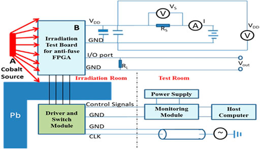
FIGURE 1. Experiment principle of FPGA TID irradiation. (A represents the Cobalt Source and B represents the Irradiation Test Board for anti-fuse FPGA.)
The experimental sample is an anti-fuse FPGA LC1020B, and its electrical characteristics test conditions specify that the input voltage VDD should be 4.5–5.5 V, and the operating temperature should be −55°C–125°C.The number of samples is 3, as shown in Table 1.

TABLE 1. Total ionizing dose irradiation sample.
In order to avoid the irradiation damage of experimental testers and high-value electronic equipment, the in-situ cobalt source irradiation experiment is carried out through the anti-fuse FPGA radiation effect detection equipment. The experimental layout is shown in Figure 2, and the experimental configuration is listed in Table 2.
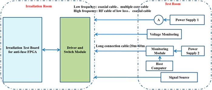
FIGURE 2. Schematic diagram of irradiation testing system.
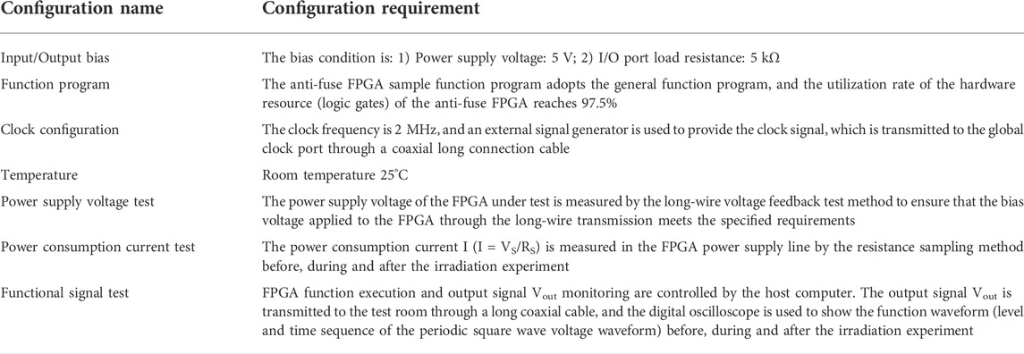
TABLE 2. Experimental configuration.
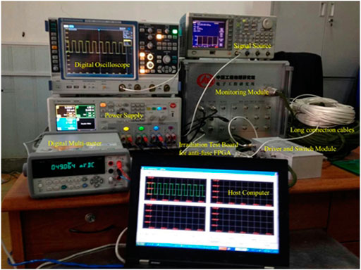
FIGURE 3. Physical connection diagram of detection equipment.
The irradiation source, anti-fuse FPGA radiation effect detection equipment, and general electrical parameter test instruments involved in the experiment and their related parameters are listed in Table 3.
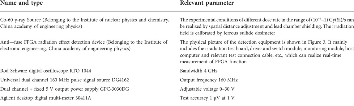
TABLE 3. The experimental instruments and equipment.
Two LC1020B anti-fuse FPGAs (numbered 101# and 102#, respectively) from the same lot were selected as the experimental samples. The initial power supply voltage was set at about 5 V, and the irradiation dose rate was 171 and 26.83 mGy/s, respectively. The experimental data of the power supply voltage, power consumption current and function of the sample changing with the irradiation dose are listed in Table 4.
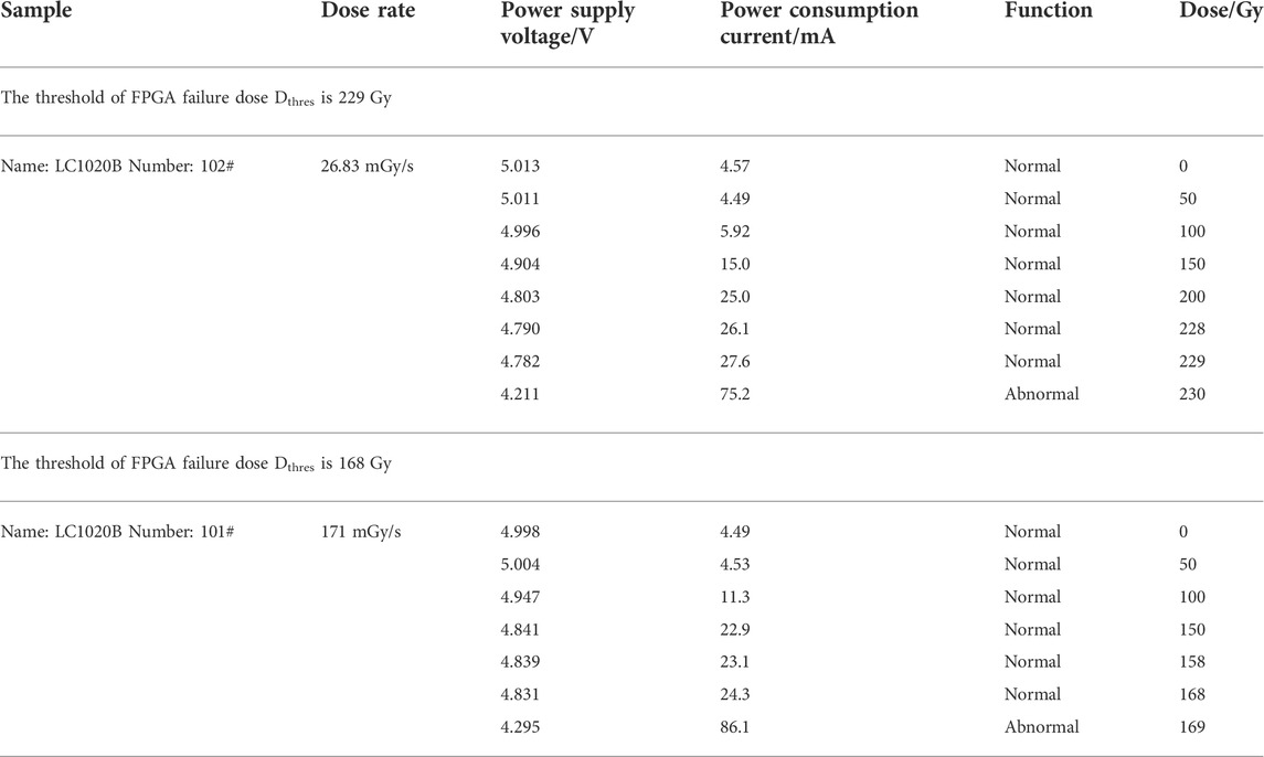
TABLE 4. Irradiation results of anti-fuse FPGA.
As can be seen from Table 4, no matter which dose rate is used to carry out experiment, the power supply current of the anti-fuse FPGA device increases with the increase of the irradiation dose, and the power supply voltage decreases with the increase of the irradiation dose (the current increases, the voltage drop on the long connection cable increases, so the input voltage of the sample decreases). When the dose rate is 171 mGy/s, the FPGA failure dose threshold is 168 Gy, and the failure current threshold is 24.3 mA; when the dose rate is 26.83 mGy/s, the FPGA failure dose threshold is 229 Gy, and the failure current threshold is 27.6 mA. From what was said above, the lower the dose rate, the larger the failure dose threshold.
However, since the operating voltage range of the sample is 4.5–5.5 V, and the bias voltage has dropped to 4.295 or 4.211 V when the sample fails, the possibility of sample failure caused by the decrease of input voltage cannot be excluded.
In order to exclude the possibility of sample failure caused by the decrease of input voltage, another LC1020B anti-fuse FPGA (No. 103#) from the same lot was selected as the experimental sample. The 4.2 V bias power supply voltage test was conducted on the sample before irradiation, and it was found that the sample could work normally. During irradiation, the initial power supply voltage of the experimental sample was set as 5.5 V, and the dose rate of irradiation was 2.68 mGy/s. The experimental data of the power supply voltage, power consumption current and function of the sample changing with the irradiation dose are listed in Table 5.
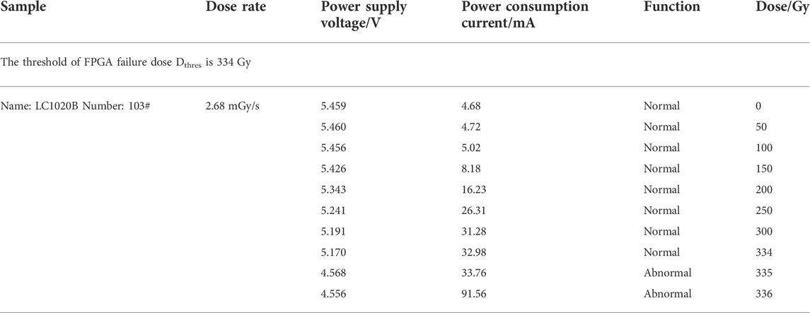
TABLE 5. Irradiation result of anti-fuse FPGA at 2.68 mGy/s dose rate.
As can be seen from Table 5, when the sample fails, the input voltage is 4.568 V, which excludes the factor that the input voltage parameter exceeds the standard and causes the FPGA failure. Under the condition of 2.68 mGy/s dose rate, the failure dose threshold of FPGA is 334 Gy, and the failure current threshold is 32.98 mA.
As can be seen from Table 4 and Table 5, no matter which dose rate is used to carry out irradiation experiment, the power consumption current of the anti-fuse FPGA increases with the increase of irradiation dose. The lower the irradiation dose rate, the greater the failure dose threshold and failure current threshold of the FPGA.
Based on the above experimental results, it takes 2,077 min for 2.68 mGy/s irradiation to reach the FPGA failure dose threshold of 334 Gy; it takes 167 min for 26.83 mGy/s irradiation to reach the FPGA failure dose threshold of 229 Gy; it only takes 16 min for 171 mGy/s irradiation to reach the FPGA failure dose threshold of 168 Gy. Within the dose rate range of this experiment, the power consumption current of the FPGA experimental samples increases with the increase of irradiation dose, and irradiation dose rate is lower, failure dose threshold and failure current threshold of FPGA is higher. There is apparent damage mitigation phenomenon for lower dose rate irradiation, in other words, the irradiation dose rate is lower, the FPGA is more resistant to radiation.
Through the above experimental phenomenon and law analysis, the following understandings are obtained:
1) Within the dose rate range of this experiment, it is speculated that, for the TID effect of FPGA samples, the influence of space charge field at different dose rates on the trapping charge generation at the interface is not the dominant effect mechanism, but the annealing effect of oxide charge at room temperature with time is the dominant effect mechanism.
2) When the FPGA fails due to 26.83 and 171 mGy/s irradiation, the input voltage is 4.2–4.3 V, and the voltage value is out of standard tolerance (<4.5 V); When the FPGA fails due to 2.68 mGy/s irradiation, the input voltage is 4.568 V and the voltage was not out of standard tolerance (>4.5 V). Therefore, it was recognized that the failure of FPGA sample was not caused by the input voltage out of standard tolerance. The 4.2 V bias supply voltage test of the sample before irradiation also proved this point.
3) When the irradiation accumulative dose is small, the power consumption current of the anti-fuse FPGA increases slowly; when the accumulative dose reaches a certain threshold, the power consumption current increases sharply and the FPGA fails immediately. The main reason is that the isolated transistor circuit has a side effect of the TID effect, which results in enhanced leakage current, longer opening time and larger opening transient value.
For digital integrated circuits, the threshold voltage of MOSFET is changed by TID irradiation, so the power consumption current increases obviously. When the power consumption current increases to a specific value, a function failure occurs, that is, the output high level signal instantly “disappears.” Since the increase of power consumption current is the sum of the contributions of all MOS units such as storage, control and drive unit, and the instantaneous “disappearance” of output signal is mostly caused by the function loss of a certain MOS unit, which is usually caused by the threshold voltage degradation to a specific level. So power consumption current of anti-fuse FPGA is selected as the sensitive electrical parameter for TID effect model.
The correlation model of FPGA power consumption current and radiation dose is established based on the experimental data of power consumption current at different irradiation doses, which can characterize the irradiation degradation characteristics of FPGAs.
Based on the experimental data of different dose points at different dose rate (2.68, 26.8, and 171 mGy/s), the form and parameters of the numerical analytical model representing irradiation degradation characteristics of FPGAs were determined by data analysis, as shown in Eqs 1, 2, where a is the dose-rate correlation parameter; I0 is the initial current; Dthres is the threshold of FPGA failure dose; Dose is the irradiation dose received by the FPGA device; DoseRate is the irradiation dose rate of FPGA device.
The values of parameter in Eqs 1, 2 are listed in Table 6.
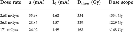
TABLE 6. The values of parameter at different dose rate.
The 100 or 200 Gy FPGA experimental data obtained based on the experiment were put into the FPGA irradiation experimental degradation analytical model, as shown in Figure 4. The experimental data and numerical prediction results were basically consistent within the allowable error range.
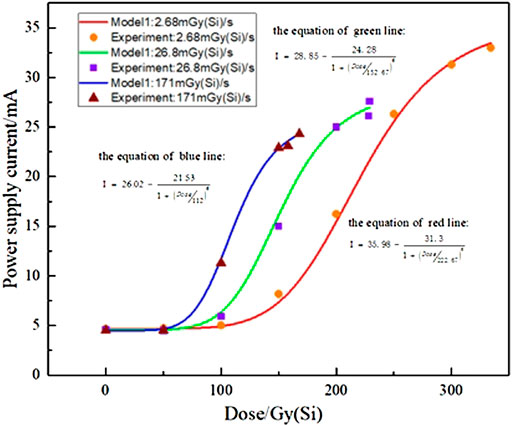
FIGURE 4. Experiment and Simulation results of FPGA TID effect.
The experimental study on TID effects under different dose rates for anti-fuse FPGA LC1020B was carried out, and the following conclusions were obtained:
1) Within the dose rate range of this experiment, the lower the dose rate, the higher the failure dose threshold of the anti-fuse FPGA, that is, the lower the dose rate, the more radiation resistant. It is speculated that the underlying physical mechanism is the dominant effect of oxide charge annealing in FPGA devices at room temperature.
2) The observed failure of the anti-fuse FPGA has nothing to do with the insufficiency of input power supply voltage parameter.
In addition, an analytical degradation model of TID effect of the anti-fuse FPGA is established based on experimental data. The model can be used to rapidly predict the degradation degree of FPGA performance at different irradiation doses of specific dose rates, which lays a foundation for scientific evaluation of radiation effect of anti-fuse FPGAs.
The raw data supporting the conclusion of this article will be made available by the authors, without undue reservation.
ML, XX, and CZ designed the research, conducted the literature review, experiment and wrote this manuscript. All authors contributed to the literature review, discussion of the results and edited the manuscript.
The authors declare that the research was conducted in the absence of any commercial or financial relationships that could be construed as a potential conflict of interest.
All claims expressed in this article are solely those of the authors and do not necessarily represent those of their affiliated organizations, or those of the publisher, the editors and the reviewers. Any product that may be evaluated in this article, or claim that may be made by its manufacturer, is not guaranteed or endorsed by the publisher.
1. Swift G, Katz R. An experimental survey of heavy ion induced dielectric rupture in Actel Field Programmable Gate Arrays (FPGAs). IEEE Trans Nucl Sci (1996) 43:967–72. doi:10.1109/23.510741
2. Lee D. Modeling the reliability of highly scaled field-programmable gate arrays in ionizing radiation. [Los Angeles, (CA)]: University of Southern California (2016). [dissertation/doctoral thesis].
3. Quinn H. Radiation effects in reconfigurable FPGAs. Semicond Sci Technol (2017) 32:044001. doi:10.1088/1361-6641/aa57f6
4. Wang JJ, Katz RB, Sun JS, Cronquist BE, McCollum JL, Speers TM, et al. SRAM based re-programmable FPGA for space applications. IEEE Trans Nucl Sci (1999) 46:1728–35. doi:10.1109/23.819146
5. Hughes HL, Benedetto JM. Radiation effects and hardening of MOS technology: Devices and circuits. IEEE Trans Nucl Sci (2003) 50:500–21. doi:10.1109/TNS.2003.812928
6. Clark SD, Bings JP, Maber MC, Williams MK, Alexander DR, Pease RL. Plastic packaging and burn-in effects on ionizing dose response in CMOS microcircuits. IEEE Trans Nucl Sci (1995) 42:1607–14. doi:10.1109/23.488756
7. Bricas G, Tsiligiannis G, Touboul A, Boch J, Maraine T, Saigne F. FPGA benchmarking structures dedicated to TID parametric degradation evaluation. IEEE Trans Nucl Sci (2022) 69:1453–60. doi:10.1109/TNS.2022.3180107
8. Lentaris G, Maragos K, Soudris D, Di Capua F, Campajola L, Campajola M, et al. TID evaluation system with on-chip electron source and programmable sensing mechanisms on FPGA. IEEE Trans Nucl Sci (2019) 66:312–9. doi:10.1109/TNS.2018.2885713
9. Gingrich DM, Buchanan NJ, Chen L, Liu S. Ionizing radiation effects in EPF10K50E and XC2S150 programmable logic devices. IEEE Radiat Effects Data Workshop (2002) 1:41. doi:10.1109/REDW.2002.1045530
10. Mikkola EO, Vermeire B, Parks HG, Graves R. VHDL-AMS modeling of total ionizing dose radiation effects on CMOS mixed signal circuits. IEEE Trans Nucl Sci (2007) 54:929–34. doi:10.1109/TNS.2007.903185
11. Katz R, LaBel K, Wang JJ, Cronquist B, Koga R, Penzin S, et al. Ratidiaon effects on current field programmable technologies. IEEE Trans Nucl Sci (1997) 44:1945–56. doi:10.1109/23.658966
12. Baoping H, Guizhen W, Hui Z, Jiancheng G, Yinhong L, Hui J. Predicting NMOS device radiation response at different dose rates in gamma-ray environment. Acta Phys Sin (2003) 52:188-91. doi:10.7498/aps.52.188
13. Shaneyfelt MR, Schwank JR, Fleetwood DM, Winokur PS. Effects of irradiation temperature on MOS radiation response. IEEE Trans Nucl Sci (1998) 45:1372–8. doi:10.1109/23.685209
14. Chen D, Pease R, Kruckmeyer K, Forney J, Phan A, Carts M, et al. Enhanced low dose rate sensitivity at ultra-low dose rates. IEEE Trans Nucl Sci (2011) 58:2983–90. doi:10.1109/TNS.2011.2171720
15. Wang Q, Liu H, Wang S, Fei C, Zhao D, Chen S, et al. Total ionizing dose effect of gamma rays on H-gate PDSOI MOS devices at different dose rates. NUCL SCI TECH (2017) 28:151–7. doi:10.1007/s41365-017-0295-7
Keywords: anti-fuse FPGA, dose rate, TID effect, power consumption current, annealing
Citation: Liu M, Xu X, Zeng C and Xiong C (2022) A study on the influence of dose rate on total ionizing dose effect of anti-fuse field programmable gate array—The irradiation damage is attenuated at low dose rate. Front. Phys. 10:1035846. doi: 10.3389/fphy.2022.1035846
Received: 03 September 2022; Accepted: 17 October 2022;
Published: 28 October 2022.
Edited by:
Qiang Xu, Nanyang Technological University, SingaporeReviewed by:
Li Wang, Zhongshan Polytechnic, ChinaCopyright © 2022 Liu, Xu, Zeng and Xiong. This is an open-access article distributed under the terms of the Creative Commons Attribution License (CC BY). The use, distribution or reproduction in other forums is permitted, provided the original author(s) and the copyright owner(s) are credited and that the original publication in this journal is cited, in accordance with accepted academic practice. No use, distribution or reproduction is permitted which does not comply with these terms.
*Correspondence: Minqiang Liu, bGl1bWlucWlhbmcyMkBnc2NhZXAuYWMuY24=, Xianguo Xu, eGd4dUAxNjMuY29t
Disclaimer: All claims expressed in this article are solely those of the authors and do not necessarily represent those of their affiliated organizations, or those of the publisher, the editors and the reviewers. Any product that may be evaluated in this article or claim that may be made by its manufacturer is not guaranteed or endorsed by the publisher.
Research integrity at Frontiers
Learn more about the work of our research integrity team to safeguard the quality of each article we publish.