- 1State Grid Shaanxi Electric Power Research Institute, Xi’an, China
- 2State Grid Xi’an Electric Power Corporation, Xi’an, China
- 3State Grid Shaanxi Maintenance Company, Xi’an, China
- 4State Grid Weinan Electric Power Corporation, Shangluo, China
- 5School of Information and Communications Engineering, Xi’an Jiaotong University, Xi’an, China
A novel dual-band bandpass filter (BPF) is proposed with independently controllable transmission zeros (TZs) which can realize widely tunable stopband bandwidth (BW). The planar microstrip filter consists of a three-degree L-C ladder lowpass filter loaded with two unsymmetrical shorted stubs which are used to produce different TZs. By tuning the parameters of the two unsymmetrical shorted stubs, the TZs can be independently controlled. Therefore, the BPF has independent controllable center frequencies (CFs), passband bandwidths, and stopband bandwidths between adjacent passbands. All the L-C values in the equivalent circuit of the proposed filter are optimized to fulfill the design specifications. For demonstration, a dual-band BPF is designed. The measured results show good agreement with the simulated ones.
Introduction
Modern wireless communication systems need high performance filters which have controllable CFs, passband bandwidths, stopband bandwidths, and sharp rejection. Different designing structures and methods have been greatly studied [1–17]. Generally, the dual-band bandpass filter (BPF) adjusts the CFs by changing transmission poles (TPs) [1, 2]. To suppress the harmonic responses, the multiple resonant modes excited by a stepped impedance stub-loaded resonator are used to design dual-band BPFs with a wide upper stopband [3]. However, there is only one transmission zero (TZ) in the stopband. Therefore, the stopband bandwidth is narrow. By introducing more TZs in the stopband, the performances of selectivity and stopband bandwidth can be enhanced. Signal-interference principles [4–6] are applied to design single- or dual-band BPFs with broad stopband bandwidths by creating multiple TZs. To design high performance filters with multiple passbands, the method of multiple mono-frequency resonators coupling to a non-resonating node is proposed in [7]. To have more TZs, couplings between the non-resonating nodes are introduced in [8], or couplings and more open/shorted-subs [9, 10] are applied in the configurations. However, it is difficult to realize the coupling for application when the number of passband increases. Moreover, TZs introduced by the coupling matrix need to change all the coupling coefficients, so it is also difficult to independently adjust the position of TZs [11].
This study presents a novel BPF loaded with two unsymmetrical shorted stubs to introduce two different TZs in the stopband to realize the controllable stopband bandwidth. Following our early work [12], the theoretical analysis of the TZs and TPs is shown in this study, which can demonstrate that the design method has advantages of simplicity and effectiveness. A three-degree lowpass filter prototype is chosen for simplicity; the in-band performance will be improved when choosing more degrees of the lowpass filter prototype. A dual-band BPF has been designed and fabricated to verify the proposed concept.
Analysis
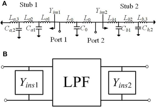
The equivalent circuit and network of the proposed prototype are shown in Figure 1. The network can be divided into three subnetworks, as shown in Figure 1B, which are the lowpass filter (LPF) section in the middle and two unsymmetrical shunt admittance sections at the sides. The LPF section is also a symmetric network and has chosen a three order L-C ladder prototype for simplicity, as shown in Figure 1A.
From our early analysis in [12], the shorted stub with two equivalent capacitors will introduce two TZs. As shown in Figure 1, the configuration has two unsymmetrical shorted stubs; the shunt admittances of Stub1 and Stub 2 have different LC values, which will produce four different TZs.
The ABCD matrix of the transmission network in Figure 1B is expressed as follows, where MY1 and MY2 are the ABCD matrices of the Stub 1 and Stub 2, respectively. MLPF is the ABCD matrix of the middle LPF section. According to the relationship of scattering parameters with the ABCD matrix, the TZs and the reflection zeros (TPs) are the roots of polynomials P(s) and F(s), respectively, where the impedance of the source/load is normalized to be 1. When the root of F(s) is an imaginary number, the reflection zero related to the root represents a TP.
From (Eq. 4b), polynomial P(s) has 4n+2 roots (n = 2), of which 2 roots are at the origin and others are conjugate and symmetrical on the imaginary axis. Therefore, each shorted stub produces n TZs and the two unsymmetrical shorted stubs produce 2n different TZs on the imaginary axis. From (Eq. 5), the degree of polynomial F(s) is 4n+5. N1(s), N2(s), b(s), and c(s) have odd terms only, while D1(s), D2(s), and a(s) have constant terms. Therefore, polynomial F(s) has one root at the origin; two real roots and the remaining 4n+2 roots are conjugate and symmetrical on the imaginary axis or in four quadrants. The optimization algorithm is used to obtain the required lumped element values for independently controlling the TZs and the return losses, such as genetic algorithm and so on.
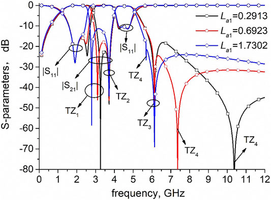
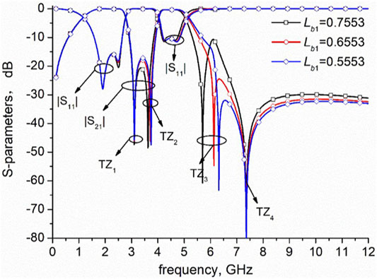
Since one of the two shorted stubs can tune two TZs, a dual-band BPF is presented for demonstration. The optimized L-C values are shown in Table 1. The S-parameters of the circuit with different parameters of the shorted stub are shown in Figures 2, 3. The parameter La1 of the shorted stub 1 can tune TZ1 and TZ4, which means the first passband CF and stopband bandwidth can be tuned independently, while the second passband width, TZ2 and TZ3 keep unchanged. The larger the value of La1, the smaller will be the frequencies of TZ1 and TZ4. Meanwhile, when the parameter Lb1 of the shorted stub 2 changes, the frequencies of TZ2 and TZ3 vary simultaneously. As shown in Figure 3, the value of Lb1 gets large and the frequencies of TZ2 and TZ3 decrease, which move at the same direction as that of TZ1 and TZ4. Therefore, the bandwidth of the second passband can be tuned independently. Since the position of the last TP is near that of TZ3, the upper stopband performance is effected by the move of TZ3.
Results
A dual-band BPF is designed and fabricated to demonstrate the design method. The CFs of dual passbands are 1 and 2.8 GHz, respectively. The stopbands are 1.75–2.2 GHz (<25 dB) and >3.55 GHz (<25 dB), respectively. Therefore, the TPs are preset as 1.8, 2.15, 3.6, and 4.4 GHz. The optimized L-C values are La1 = 0.5922, La2 = 2.5267, La3 = 3.3803, L0 = 3.0691, Lb1 = 1.1153, Lb2 = 2.4080, Lb3 = 3.9501 (unit in nH), Ca1 = 2.8256, Ca2 = 3.2161, C0 = 1.4321, Cb1 = 2.8576, and Cb2 = 3.6815 (unit in pF). The S-parameters calculated by the optimized L-C values are shown in Figure 4A. The roots of P(s) are 0, 0, ±1.83j, ±2.16j, ±3.59j, and ±4.41j, which are calculated in unit GHz for facility. The positive imaginary roots of P(s) represent the TZs. The L-C values of shunt admittance Yins1 control TZ2 and TZ4, while the L-C values of shunt admittance Yins2 control TZ1 and TZ3. The roots of F(s) are 0, −0.05 ± 1.01j, 0.1 ± 1.37j, −0.07 ± 2.59j, 0.04 ± 2.9j, 0.03 ± 3.58j, −8.94, and 15.15. Since the roots 0.03 ± 3.58j of F(s) are close to the roots ±3.59j of P(s), the second passband has two TPs not three TPs [7].
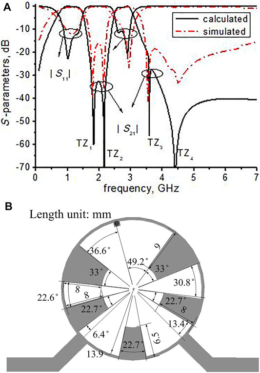
FIGURE 4. Calculated and measured S-parameters and optimized structure (A) calculated and simulated S-parameters (B) optimized BPF structure.
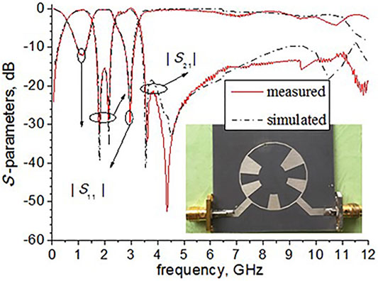
The BPF is simulated and fabricated on a substrate with εr = 2.65, tanδ = 0.003, and h = 1 mm. Here, we choose the 117.8 Ω high-impedance line, which has the line-width of 0.5 mm. As shown in Figure 4B, the line width of the open stub which acts as the capacitor is tapered. The characteristic impedance is calculated by the waist width of the taper. Due to the discontinuity of the microstrip line and the minor coupling between the open stubs, the final dimension parameters are optimized by the full-wave electromagnetic simulation software HFSS. The optimized values of parameters are given in Figure 4B. The circuit size is about 0.15 λg × 0.15 λg, where λg is the guided wavelength at f01. The simulated S-parameters agree well with the calculated ones, as shown in Figure 4A. Figure 5 shows the simulated and measured S-parameters with the photograph inset. The measured results are in good agreement with the simulated ones. The discrepancies between the simulated results and the measured results may be due to the ignorance of transmission line discontinuity and fabrication tolerances. The measured CFs, fractional bandwidths (FBWs), insertion losses (ILs) at the CF, out-band suppressions (OBSs), the number of controllable TZs, and the size are listed in Table 2. As shown in Table 2, the proposed dual-band BPF with simple circuit topology has advantages such as relative low IL, wide FBW, wide upper stopband, and more controllable TZs.
Conclusion
A dual-band BPF with a controllable stopband bandwidth between the passbands is designed by the method of independently controlling TZs. By tuning the parameters of the two unsymmetrical shorted stubs, the introduced two TZs between adjacent passbands can be independently controlled. After optimizing the equivalent circuit lumped element values, the CFs, passband bandwidths, and stopband bandwidths can be tuned in a certain range. With a simple filter structure and good performance, the proposed method is attractive for application in high-selectivity filter designs.
Data Availability Statement
The original contributions presented in the study are included in the article/Supplementary Material; further inquiries can be directed to the corresponding author.
Author Contributions
All authors listed have made a substantial, direct, and intellectual contribution to the work and approved it for publication.
Conflict of Interest
Authors NW and HW were employed by the State Grid Shaanxi Electric Power Research Institute. KG and XR were employed by the company State Grid Xi'an Electric Power Corporation. XC was employed by the State Grid Shaanxi Maintenance Company. QX was employed by the State Grid Weinan Electric Power Corporation.
The remaining authors declare that the research was conducted in the absence of any commercial or financial relationships that could be construed as a potential conflict of interest.
Publisher’s Note
All claims expressed in this article are solely those of the authors and do not necessarily represent those of their affiliated organizations, or those of the publisher, the editors, and the reviewers. Any product that may be evaluated in this article, or claim that may be made by its manufacturer, is not guaranteed or endorsed by the publisher.
References
1. He J, Chen C-m. A Dual-Band BPF with Controllable Center Frequencies and Bandwidths Using a Single SIW Cavity. In: Prceeding of the 2021 IEEE 4th International Conference on Electronics Technology (ICET); 7-10 May 2021; Chengdu, China. IEEE (2021). p. 489–92. doi:10.1109/ICET51757.2021.9451069
2. Lin W, Lee T-H, Wu K Dual-Band Bandpass SIW Resonator Filter with Flexible Frequency Ratio. In: Prceeding of the 2019 49th European Microwave Conference (EuMC); 1-3 Oct. 2019; Paris, France. IEEE (2019). p. 364–7. doi:10.23919/EuMC.2019.8910700
3. Lin L, Sun SJ, Wu B, Liang CH Dual‐band Bandpass Filter with Wide Upper Stopband Using Quad‐mode Stepped Impedance Stub‐loaded Resonator. Electron Lett (2014) 50(16):1145–6. doi:10.1049/el.2014.2004
4. Sanchez-Soriano MA, Gomez-Garcia R Sharp-Rejection Wide-Band Dual-Band Bandpass Planar Filters with Broadly-Separated Passbands. IEEE Microw Wireless Compon Lett (2015) 25(2):97–9. doi:10.1109/LMWC.2014.2382669
5. Phani Kumar KV, Karthikeyan SS Compact, High Selectivity and Wideband Bandpass Filter with Multiple Transmission Zeros. AEU - Int J Electronics Commun (2018) 94:79–83. doi:10.1016/j.aeue.2018.06.047
6. Yogesh SS, Phani K, Karthikeyan SS Compact Dual-Wideband Bandpass Filter for Wireless Applications. AEU - Int J Electronics Commun (2018) 95:S1434841118304618. doi:10.1016/j.aeue.2018.08.007
7. Gomez-Garcia R, Guyette AC Reconfigurable Multi-Band Microwave Filters. IEEE Trans Microwave Theor Techn. (2015) 63(4):1294–307. doi:10.1109/TMTT.2015.2405066
8. Gómez-García R, Guyette AC, Psychogiou D, Naglich EJ, Peroulis D Quasi-Elliptic Multi-Band Filters with Center-Frequency and Bandwidth Tunability. IEEE Microwave Wireless Components Lett (2016) 26(3):192–4. doi:10.1109/LMWC.2016.2526026
9. Xu K-D, Li D, Liu Y High-Selectivity Wideband Bandpass Filter Using Simple Coupled Lines with Multiple Transmission Poles and Zeros. IEEE Microw Wireless Compon Lett (2019) 29(2):107–9. doi:10.1109/LMWC.2019.2891203
10. Xu KD, Zhang F, Liu Y, Nie W High Selectivity Seventh‐order Wideband Bandpass Filter Using Coupled Lines and Open/shorted Stubs. Electron Lett (2018) 54(4):223–5. doi:10.1049/el.2017.4233
11. Tang S-C, Chu P-C, Kuo J-T, Wu L-K Dual-band Bandpass Filter Based on Frequency Transformations with Enhanced Inter-band Isolation. In: Prceeding of the 2020 IEEE Asia-Pacific Microwave Conference (APMC); 8-11 Dec. 2020; Hong Kong, Hong Kong. IEEE (2020). p. 758–60. doi:10.1109/APMC47863.2020.9331380
12. Yang Q, Jiao YC, Zhang Z Dual‐wideband BPF with Wide Upper Stopband Using Shorted Stepped‐impedance Stub‐loaded Lowpass Filter. Electron Lett (2016) 52(19):1615–6. doi:10.1049/el.2016.2475
13. Xu J, Wu W, Miao C Compact and Sharp Skirts Microstrip Dual-Mode Dual-Band Bandpass Filter Using a Single Quadruple-Mode Resonator (QMR). IEEE Trans Microwave Theor Techn. (2013) 61(3):1104–13. doi:10.1109/tmtt.2013.2238949
14. Sun S-J, Su T, Deng K, Wu B, Liang C-H Compact Microstrip Dual-Band Bandpass Filter Using a Novel Stub-Loaded Quad-Mode Resonator. IEEE Microw Wireless Compon Lett (2013) 23(9):465–7. doi:10.1109/LMWC.2013.2274038
15. Peng Y, Zhang L, Fu J, Wang Y, Leng Y Compact Dual-Band Bandpass Filter Using Coupled Lines Multimode Resonator. IEEE Microw Wireless Compon Lett (2015) 25(4):235–7. doi:10.1109/LMWC.2015.2400936
16. Jin X, Wen W, Chen M Compact Microstrip Dual-/Tri-/Quad-Band Bandpass Filter Using Open Stubs Loaded Shorted Stepped-Impedance Resonator. IEEE Trans Microwave Theor Tech (2013) 61(9):3187–99. doi:10.1109/TMTT.2013.2273759
Keywords: bandpass filter, dual-band, tunable stopband, wide upper stopband, transmission zeros, transmission poles
Citation: Wang N, Wei H, Gao K, Ruan X, Chen X, Xu Q, Yang Q, Zhang A and Liu S (2022) Dual-Band Bandpass Filter With Controllable Stopband Bandwidth. Front. Phys. 9:809752. doi: 10.3389/fphy.2021.809752
Received: 05 November 2021; Accepted: 29 November 2021;
Published: 03 January 2022.
Edited by:
Zhewang Ma, Saitama University, JapanReviewed by:
Weiren Zhu, Shanghai Jiao Tong University, ChinaYijun Cai, Xiamen University of Technology, China
Copyright © 2022 Wang, Wei, Gao, Ruan, Chen, Xu, Yang, Zhang and Liu. This is an open-access article distributed under the terms of the Creative Commons Attribution License (CC BY). The use, distribution or reproduction in other forums is permitted, provided the original author(s) and the copyright owner(s) are credited and that the original publication in this journal is cited, in accordance with accepted academic practice. No use, distribution or reproduction is permitted which does not comply with these terms.
*Correspondence: Shuangyang Liu, bHN5NjgyMEBzdHUueGp0dS5lZHUuY24=
 Nan Wang1
 Qian Yang
 Shuangyang Liu