 Bowen Su1
 Jueping Cai
- 1Key Laboratory of Wide Bandgap Semiconductor Materials, School of Microelectronics, Xidian University, Xi’an, China
- 2School of Information and Software Engineering, University of Electronic Science and Technology of China, Chengdu, China
A synaptic structure with memristor state initialization function and a neuronal circuit with structural variability are presented in this article. In contrast to the popular use of voltage as a medium for containing information and realizing the computational function of a neuron in the form of voltage–current–voltage, the proposed neuron circuit adopts current as a carrier of information; also the computation will be realized in the form of current–voltage instead. Since the sum of currents can be achieved by direct connection, this will greatly reduce the hardware area of the artificial neuron. In addition, by adjusting the switches, the initialization of the memristor can be implemented, and the process of structural changes of neurons in biology can also be mimicked. Comparing with several popular synaptic circuits, it is proven that the π-type synapse has more structural advantages. Simulations show that the π-type synaptic structure can obtain the specified weight value faster and complete the initial state setting of the memristors in 1.502 ms. Even in the worst case, where the weight needs to be changed from −1 to 1, it can be completed in only 1.272 ms. Under the condition of achieving the same function, the area of the proposed neuron with 100 synapses will be reduced by at least 97.42%. Moreover, there is better performance in terms of linearity.
Introduction
Synapses are abundant in the human brain which consists of approximately
When information is transmitted in a neuron, the postsynaptic membrane will produce different degrees of physiological response depending on the number of neurotransmitters, which is always abstracted as the degree of involvement of each synapse in a practical circuit design, that is, the weight that each synapse occupies in the neuron and the storage of such non-volatile weights is often hosted by resistors, capacitors, or CMOS transistors. However, in the previous implemented circuits, the storage of weights in resistors cannot change with the network due to the fixed resistance value, and those stored by capacitors are subject to charge leakage as well. To represent a synapse through conventional CMOS circuits, approximately 10 transistors will be required, [3] which will be limited by the hardware size in the post-Moore era, making it difficult to carry out the demand for smaller size.
Since the concept of the memristor was proposed [4], it has attracted much attention in bio-synaptic implementation circuits due to its unique hysteresis curve characteristics, non-volatility of its resistive state and smaller size, and the good compatibility with conventional CMOS processes. Take the voltage-controlled memristor in [5] as an example; it is the first device with the function of the memristor whose resistance value will change accordingly by adjusting the voltage applied to both ends of the memristor, showing its potential as a malleable small-sized synapse. More memristor models have been proposed later, and they can be divided into flux-controlled [6, 7] and charge-controlled [8–10] memristors according to the factors which determine the memristance. Recently, some new models have been proposed, such as the discrete memristor [11]. Because of its unique nonlinearity, it has been widely used in chaotic circuits [12, 13]. Using the hysteresis characteristics of the memristor, it can also be used to connect [14] and construct neurons [15–20]. As the production process of memristors becomes more and more mature, they are now widely used in the fields of intelligent bionics, human–computer interaction, and neural network computing, etc. [21–25].
The application of memristors in artificial neurons has become very general. Several common circuits [26] that used memristors to achieve synaptic function either did not achieve the full range of weights, such as positive, negative, and 0 for they used memristance as weight [15, 20, 27], or the change of weight was in a nonlinear form [15, 20, 28] or the weight symbol needed to be set additionally [20]; even the most commonly used memristor bridge circuit, called 4M structure [23, 29], did not take it into account that it is not enough to simply indicate the initial state of the memristor since memristors are generally manufactured in a high-resistance state from the factory. The 4M circuit structure did not involve the problem of setting the initial state value of the memristor. In addition, none of the abovementioned existing structures have been designed for this phenomenon, which is, in the developing process of the actual living organism; synapses will have fresh growth and fading, and that will result in the change of the neuronal structure. Although the 2M structure and with dual input modes [18, 30] in recent years are improved compared with those mentioned above, they still do not have any advantage in the area due to the existence of resistances.
Changes in the structure of a single neuron and in the connection of multiple neurons can reflect the flexibility of the design, and there are many ways to realize the plasticity. The coupling channel between different neurons structured by Josephson junction is proven to be able to detect the synchronization between two neural circuits and speed up the calculation [31, 32]. Several combinations of capacitance, inductance, and resistance can constitute hybrid synapses [33–36]and effectively bridge the neural circuit, which regulates the synchronization of different neurons. Memristors can also be used as part of the coupling channel [14]. By selecting the composition of the coupling channel and adjusting the parameters, the neural circuit can be induced to transition from synchronization to non-synchronization. This process can also be seen as the plasticity of the circuit structure.
In this article, a new basic unit π-type structure of the synapse, and in addition to this, the artificial neuron unit composed of this synapse has been proposed. First of all, this structure can realize the basic functions of synapses, implying it can represent the full range of weights, namely, positive, negative, and zero. Second, the initial resistance states of the memristors can be adjusted by controlling the switches of the π-type basic unit; third, the structural plasticity of the neurons and the degradation and regeneration process of synapses that happen in actual neurons by controlling the working state of each basic unit are also simulated; at last, considering the large number of synapses on each neuron, when the π-structure synapses are used to build a complete neuron, the information contained in each synapse is aggregated in the form of current and then passed through the same conversion circuit that takes current into voltage, which has greatly reduced the area required to simulate neurons.
In the following article, Memristor Models introduced the basic principles of the memristor and
Memristor Models
The memristor is proposed by Leon Chua as the fourth type of electronic devices and is defined as a certain connection between flux and charge [4]:
HP Labs [5] reported that the metal–oxide–metal structure can be used as a mathematical model of the memristor and made electronic components with memristor characteristics successfully by using two layers of the
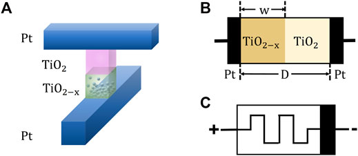
FIGURE 1. (A) Schematic diagram of the implementation of the HP model in physics. (B) Sandwich structure comprising
The resistance of the memristor can be expressed as follows:
And the v–i characteristics can be expressed as follows:
where
where
The difference from the abovementioned fact is that it is believed that the boundary between the doped and undoped parts moves at a uniform speed in the linear drift model, but in fact, when
The relationship between the width of the doped region
where
The curve of
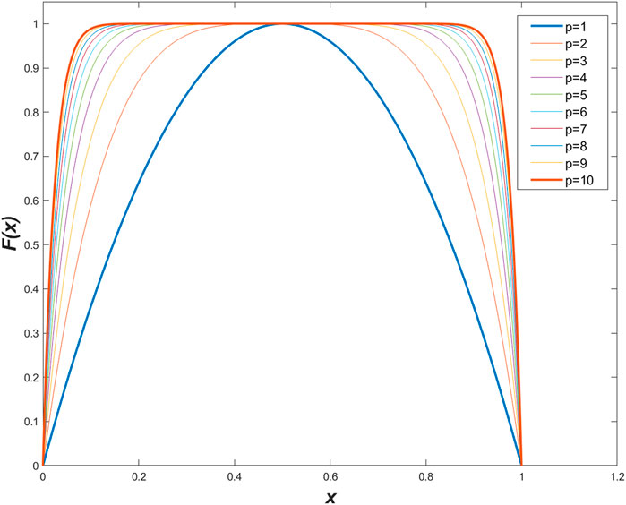
FIGURE 2. Variation curve of window function
The influence of the direction of the connected memristor on its resistance when the memristor is input voltages in different directions is discussed as follows. The difference in the concentration of drifting oxygen ions at both ends of the memristor determines that the input of positive and negative excitations to the memristor will have different results.
It is stipulated that the doped end is the positive side of the memristor, and the non-doped end is the negative side, and it can be divided into the following four cases as shown in Table 1:

TABLE 1. Influence of input direction and voltage polarity on memristance.
Case 1. When a positive voltage is connected to the positive terminal of the memristor, the interface between the doped region and undoped of memristor will float along the direction of the voltage decrease, which will cause the width of the doped region to increase and the memristance to decrease. The memristor at this time is connected in the forward direction.
Case 2. When a negative voltage is connected to the positive electrode of the memristor, the voltage tends to cause the interface to float toward the positive electrode of the memristor, and the width will decrease, which will cause the memristance value to increase.
In the same way, from case 3 and case 4, it can be known that when the voltage is input from the negative terminal of the memristor, the positive and negative voltages will increase and decrease the resistance of the memristor, respectively.
The memristance curves of the four cases are shown in Figure 3. It should be noted that the minimum value of the resistance of the memristor needs to be controlled and the maximum value needs to be
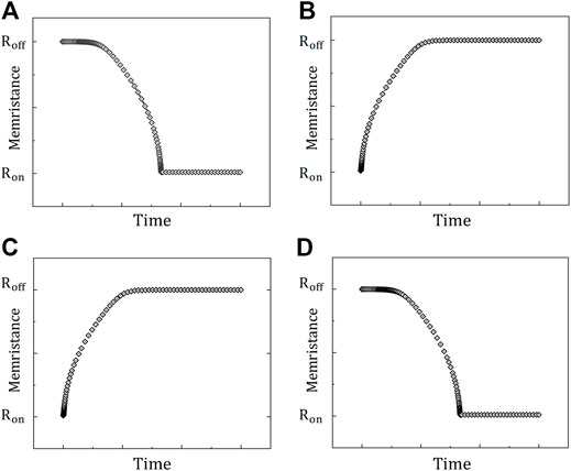
FIGURE 3. Influence of the memristor access direction and excitation direction to memristance. (A) Memristor is positively connected and positive excitation is applied (B) Memristor is positively connected and negative excitation is applied. When the memristor is connected in reverse, (C) applying a forward excitation to the memristor will increase the resistance, and (D) a reverse excitation will reduce the resistance.
π-Type Memristor Synapse and Neuron
The proposed basic unit of the synaptic circuit based on the memristor is shown in Figure 4. It consists of five flux-controlled memristors and three switches, in which
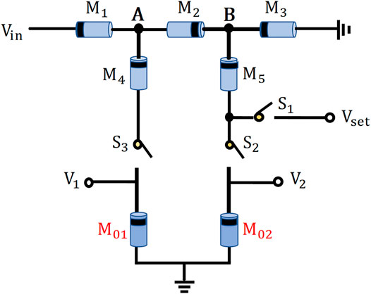
FIGURE 4. Proposed
Initialization State Setting
Part of the existing synaptic circuits based on memristors [19, 20]only specified the initial status of memristors and did not explain how to complete the initial resistance setting in their actual circuits, without considering that memristors are often in a high-impedance state when they are manufactured. The method to set the initial states in our synaptic circuit based on the memristor is proposed, as shown in Figure 5.
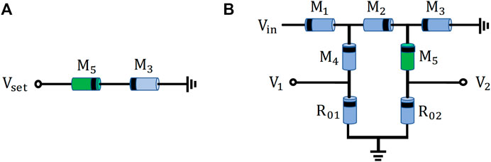
FIGURE 5. Method of initializing the memristors. (A) Positive excitation initialization signal is input and passes only through
During the growth of neurons, new synapses often appear, and a part of them is also pruned, and this variability is called structural plasticity, whereas in the previously proposed analog synaptic circuits, only the weights occupied by the synapses can be changed, but not the structure because of their fixity. The
Weight Setting
The states of the memristors after the initial setup are set as
The resistances between the node A and ground and between node B and ground can be expressed as follows:
The total resistance of one synapse can be expressed as follows:
Suppose there is an input voltage
The currents passing through the branches where
Using two transistors can convert the current signal into voltage, and the output voltage
This formula can be interpreted as the relationship between a synaptic input
The abovementioned equations can be considered a weighting operation of every
The current memristor-based synapses can be classified according to the number of memristors into 1M [15, 16], 2M [17, 18], 4M [19], and 5M [20]. Table 2 lists the following points: The components of the synapse, the range of weights that can be expressed, whether it is necessary to set the weight symbols in advance, the performance of linearity, and whether it has the initialization function of the memristor. It intuitively demonstrated the superiority of the

TABLE 2. Comparison of the characteristics of several common memristor synapses.
Artificial Neuron Structure Based on the Proposed Synapse
In the actual biological nervous system, the network-like information interactions will be completed in the form of which neurons collect and process different information collected by each synapse, and then they transmit the processed signals to the neurons of the next layer. A neuron structure based on this synaptic structure is further designed, which can realize the transmission of information in the form of electric current in the neuron so that it will eliminate the traditional cumbersome steps when building a large neural network and save a lot of area. The complete circuit of the multi-input memristor neuron comprising the
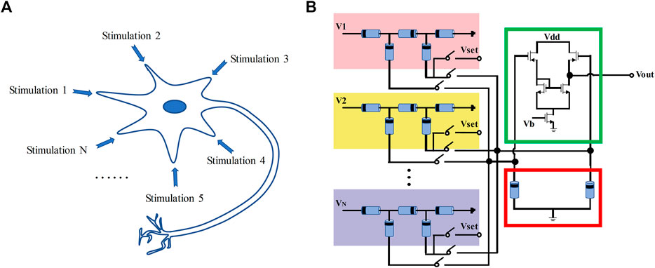
FIGURE 6. Comparison of neuronal biological schematics with the proposed neuron structure. (A) Neuronal biological schematics. (B) Structural diagram of a neuronal circuit composed of the
Weight Setting of π-Structure
As the input signal for setting weight of the
Similarly, when negative and zero weights are required, the conditions should be satisfied as follows:
Negative weight:
Zero weight:
It is essential to be note here that the pulse width of the setting signal must be wide enough to bring about a change in the memristor value, as opposed to the need to keep the pulse width of the input signal within a small range when calculating with the given weights, which can avoid the change of the memristors.
Simulations and Analysis
Simulations were all performed in the MATLAB R2020a environment and based on the
Initial State Setting of the Memristor
Considering that the freshly shipped memristors generally present a high-resistance state, we simulated the setting of the memristor state to the desired initial state by controlling the switch statement. Figure 5A demonstrates that
According to Figure 7, in that
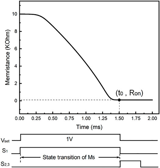
FIGURE 7. Curve of memristance of
Weight Setting
A pulse signal with an amplitude of 1V and a width that varies with the time required to traverse the full range of weights was used for setting the weight. Weight setting should be performed after all available synapses have been initialized. After that, when
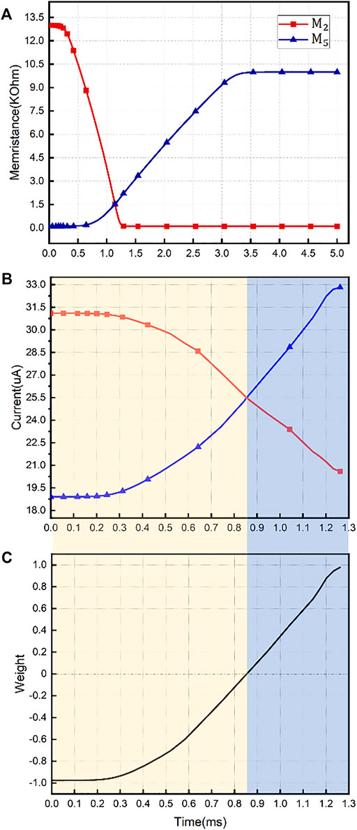
FIGURE 8. (A) Memristance curve of
Analysis
Considering the boundary effect of the actual memristive device, the nonlinear
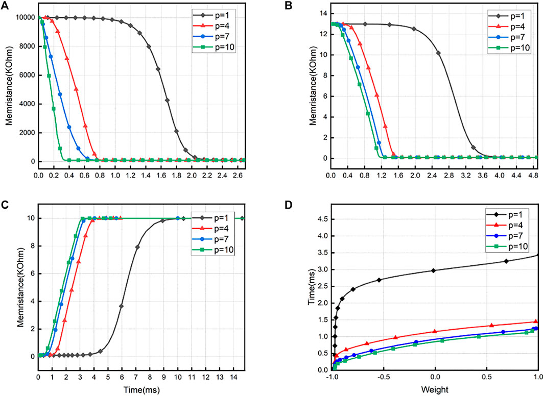
FIGURE 9. Influence of
In the case of achieving the same function, a neuron comprising 100 synapses is represented by the most commonly used memristor bridge circuit, which requires 401 memristors and 304 transistors, while that in the proposed neuron structure with the
Conclusion
A π-type artificial synaptic structure that utilizes the nonvolatile nature of amnestic resistors was suggested by this article, and further an artificial neuron structure with structural variability is also proposed based on this synaptic structure. Our artificial synaptic basic unit consists of five amnestic resistors, and by applying a variable-width pulse input signal with a forward amplitude of 1V, the information will be located in the form of current, and the weight setting is implemented. Simulations using the nonlinear model of
Data Availability Statement
The raw data supporting the conclusions of this article will be made available by the authors, without undue reservation.
Author Contributions
BS, ZW, and YZ designed the research. JC and JC guided the research. All authors contributed to the interpretation of the results, discussions, and editing of the manuscript. Furthermore, all authors have read and agreed to the published version of the manuscript.
Funding
This study was supported by the Natural Science Basic Research Plan in Shaanxi Province of China (2021ZDLGY02-01) and the National 111 Center.
Conflict of Interest
The authors declare that the research was conducted in the absence of any commercial or financial relationships that could be construed as a potential conflict of interest.
Publisher’s Note
All claims expressed in this article are solely those of the authors and do not necessarily represent those of their affiliated organizations, or those of the publisher, the editors, and the reviewers. Any product that may be evaluated in this article, or claim that may be made by its manufacturer, is not guaranteed or endorsed by the publisher.
References
1. Zidan MA, Chen A, Indiveri G, Lu WD. Memristive Computing Devices and Applications. J Electroceram (2017) 39(1):4–20. doi:10.1007/s10832-017-0103-0
2. Guo T, Sun B, Ranjan S, Jiao Y, Wei L, Zhou YN, et al. From Memristive Materials to Neural Networks. ACS Appl Mater Inter (2020) 12(49):54243–65. doi:10.1021/acsami.0c10796
3. Yang R, Huang HM, Guo X. Memristive Synapses and Neurons for Bioinspired Computing. Adv Electron Mater (2019) 5:1900287. doi:10.1002/aelm.201900287
4. Chua L. Memristor-The Missing Circuit Element. IEEE Trans Circuit Theor (1971) 18(5):507–19. doi:10.1109/TCT.1971.1083337
5. Strukov DB, Snider GS, Stewart DR, Williams RS. The Missing Memristor Found. Nature (2008) 453(7191):80–3. doi:10.1038/nature06932
6. Si G, Diao L, Zhu J. Fractional-order Charge-Controlled Memristor: Theoretical Analysis and Simulation. Nonlinear Dyn (2017) 87(4):2625–34. doi:10.1007/s11071-016-3215-1
7. Wang L, Drakakis E, Duan S, He P, Liao X. Memristor Model and its Application for Chaos Generation. Int J Bifurcation Chaos (2012) 22(8):1250205. doi:10.1142/S0218127412502057
8. Batas D, Fiedler H. A Memristor SPICE Implementation and a New Approach for Magnetic Flux-Controlled Memristor Modeling. IEEE Trans Nanotechnology (2011) 10(2):250–5. doi:10.1109/TNANO.2009.2038051
9. Xie X, Zou L, Wen S, Zeng Z, Huang T. A Flux-Controlled Logarithmic Memristor Model and Emulator. Circuits Syst Signal Process (2019) 38:1452–65. doi:10.1007/s00034-018-0926-1
10. Bao H, Hu A, Liu W, Bao B. Hidden Bursting Firings and Bifurcation Mechanisms in Memristive Neuron Model with Threshold Electromagnetic Induction. IEEE Trans Neural Netw Learn Syst. (2020) 31(2):502–11. doi:10.1109/TNNLS.2019.2905137
11. Bao H, Hua Z, Li H, Chen M, Bao B. Discrete Memristor Hyperchaotic Maps. IEEE Trans Circuits Syst (2021) 68(11):4534–44. doi:10.1109/TCSI.2021.3082895
12. Wang C, Xia H, Zhou L. A Memristive Hyperchaotic Multiscroll Jerk System with Controllable Scroll Numbers. Int J Bifurcation Chaos (2017) 27(6):1750091–1219. doi:10.1142/S0218127417500912
13. Bao H, Wang N, Bao B, Chen M, Jin P, Wang G. Initial Condition-dependent Dynamics and Transient Period in Memristor-Based Hypogenetic Jerk System with Four Line Equilibria. Commun Nonlinear Sci Numer Simulation (2018) 57:264–75. doi:10.1016/j.cnsns.2017.10.001
14. Xu Y, Jia Y, Ma J, Alsaedi A, Ahmad B. Synchronization between Neurons Coupled by Memristor. Chaos, Solitons & Fractals (2017) 104:435–42. doi:10.1016/j.chaos.2017.09.002
15. Jo SH, Chang T, Ebong I, Bhadviya BB, Mazumder P, Lu W. Nanoscale Memristor Device as Synapse in Neuromorphic Systems. Nano Lett (2010) 1410(4):1297–301. doi:10.1021/nl904092h
16. Wen S, Xie X, Yan Z, Huang T, Zeng Z. General Memristor with Applications in Multilayer Neural Networks. Neural Networks (2018) 103:142–9. doi:10.1016/j.neunet.2018.03.015
17. Vo M-H. Multilayer Neural Network with Synapse Based on Two Successive Memristors. Toeej (2018) 12:132–47. doi:10.2174/1874129001812010132
18. Hong Q, Zhao L, Wang X. Novel Circuit Designs of Memristor Synapse and Neuron. Neurocomputing (2019) 330:11–6. doi:10.1016/j.neucom.2018.11.043
19. Kim H, Sah MP, Yang C, Roska T, Chua LO. Memristor Bridge Synapses. Proc IEEE (2012) 100(6):2061–70. doi:10.1109/JPROC.2011.2166749
20. Kim H, Sah MP, Yang C, Roska T, Chua LO. Neural Synaptic Weighting with a Pulse-Based Memristor Circuit. IEEE Trans Circuits Syst (2012) 59(1):148–58. doi:10.1109/TCSI.2011.2161360
21. Wen S, Xie X, Yan Z, Huang T, Zeng Z. General Memristor with Applications in Multilayer Neural Networks. Neural Networks (2018) 103:142–9. doi:10.1016/j.neunet.2018.03.015
22. Zhang Y, Wang X, Friedman EG. Memristor-Based Circuit Design for Multilayer Neural Networks. IEEE Trans Circuits Syst (2018) 65(2):677–86. doi:10.1109/tcsi.2017.2729787
23. Adhikari SP, Kim H, Budhathoki RK, Yang C, Chua LO. A Circuit-Based Learning Architecture for Multilayer Neural Networks with Memristor Bridge Synapses. IEEE Trans Circuits Syst (2015) 62(1):215–23. doi:10.1002/adfm.20200677310.1109/tcsi.2014.2359717
24. Sun K, Chen J, Yan X. The Future of Memristors: Materials Engineering and Neural Networks. Adv Funct Mater (2021) 31(8):2006773. doi:10.1002/adfm.202006773
25. Di Marco M, Forti M, Pancioni L. Memristor Standard Cellular Neural Networks Computing in the Flux-Charge Domain. Neural Networks (2017) 93:152–64. doi:10.1016/j.neunet.2017.05.009
26. Krestinskaya O, James AP, Chua LO. Neuromemristive Circuits for Edge Computing: A Review. IEEE Trans Neural Netw Learn Syst. (2020) 31(1):4–23. doi:10.1109/TNNLS.2019.2899262
27. Yang L, Zeng Z, Shi X. A Memristor-Based Neural Network Circuit with Synchronous Weight Adjustment. Neurocomputing (2019) 363:114–24. doi:10.1016/j.neucom.2019.06.048
28. Luo L, Hu X, Duan S, Dong Z, Wang L. Multiple Memristor Series-Parallel Connections with Use in Synaptic Circuit Design. IET Circuits, Devices Syst (2017) 11(2):123–34. doi:10.1049/iet-cds.2015.0357
29. Adhikari SP, Changju Yang C, Hyongsuk Kim H, Chua LO. Memristor Bridge Synapse-Based Neural Network and its Learning. IEEE Trans Neural Netw Learn Syst. (2012) 23(9):1426–35. doi:10.1109/TNNLS.2012.2204770
30. Wang L, Wang X, Duan S, Li H. A Spintronic Memristor Bridge Synapse Circuit and the Application in Memrisitive Cellular Automata. Neurocomputing (2015) 167:346–51. doi:10.1016/j.neucom.2015.04.061
31. Crotty P, Schult D, Segall K. Josephson junction Simulation of Neurons. Phys Rev E (2010) 82:011914. doi:10.1103/PhysRevE.82.011914
32. Zhang Y, Wang C, Tang J, Ma J, Ren G. Phase Coupling Synchronization of FHN Neurons Connected by a Josephson junction. Sci China Technol Sci (2020) 63:2328–38. doi:10.1007/s11431-019-1547-5
33. Wang C, Tang J, Ma J. Minireview on Signal Exchange between Nonlinear Circuits and Neurons via Field Coupling. Eur Phys J Spec Top (2019) 228:1907–24. doi:10.1140/epjst/e2019-800193-8
34. Ma J, Yang Z-q., Yang L-j., Tang J. A Physical View of Computational Neurodynamics. J Zhejiang Univ Sci A (2019) 20:639–59. doi:10.1631/jzus.A1900273
35. Xu Y-m., Yao Z, Hobiny A, Ma J. Differential Coupling Contributes to Synchronization via a Capacitor Connection between Chaotic Circuits. Front Inf Technol Electron Eng (2019) 20(4):571–83. doi:10.1631/FITEE.1800499
36. Liu Z, Wang C, Zhang G, Zhang Y. Synchronization between Neural Circuits Connected by Hybrid Synapse. Int J Mod Phys B (2019) 33(16):1950170. doi:10.1142/S0217979219501704
37. Joglekar YN, Wolf SJ. The Elusive Memristor: Properties of Basic Electrical Circuits. Eur J Phys (2009) 30(4):661–75. doi:10.1088/0143-0807/30/4/001
Keywords: memristor synapse, neuron structure, structural plasticity, integrated circuit design, signal processing
Citation: Su B, Cai J, Wang Z, Chu J and Zhang Y (2022) A π-Type Memristor Synapse and Neuron With Structural Plasticity. Front. Phys. 9:798971. doi: 10.3389/fphy.2021.798971
Received: 20 October 2021; Accepted: 10 December 2021;
Published: 12 January 2022.
Edited by:
Karthikeyan Rajagopal, Chennai Institute of Technology, IndiaReviewed by:
Jun Ma, Lanzhou University of Technology, ChinaBocheng Bao, Changzhou University, China
Copyright © 2022 Su, Cai, Wang, Chu and Zhang. This is an open-access article distributed under the terms of the Creative Commons Attribution License (CC BY). The use, distribution or reproduction in other forums is permitted, provided the original author(s) and the copyright owner(s) are credited and that the original publication in this journal is cited, in accordance with accepted academic practice. No use, distribution or reproduction is permitted which does not comply with these terms.
*Correspondence: Jueping Cai, anBjYWlAbWFpbC54aWRpYW4uZWR1LmNu