- 1Department of Mechanical Engineering, Federal Institute of Technology - IFPE, Recife, Pernambuco, Brazil
- 2Department of Mechanical Engineering, University of Manitoba, Winnipeg, MB, Canada
Pump-controlled actuators, or more generically, hydrostatic actuators, have the significant advantage of not relying on valves to control the cylinders. This results in much better energy usage compared to traditional valve-controlled systems. However, it is possible to further increase energy efficiency by storing load energy in motoring quadrants and subsequently releasing the stored energy back into the circuit or making it available for other applications. Much work is needed to practically study energy storage in hydrostatic actuators. In this note, we review the two basic ways hydraulic energy can be saved in circuits using accumulators, emphasizing their advantages and drawbacks. The review is followed by a brief description of the current research being carried out at the University of Manitoba in Canada. We aim to show that research in this field is promising and demonstrates that hydraulic power transmission can not only be made efficient but also be used to regenerate load energy that would otherwise go to waste.
1 Introduction
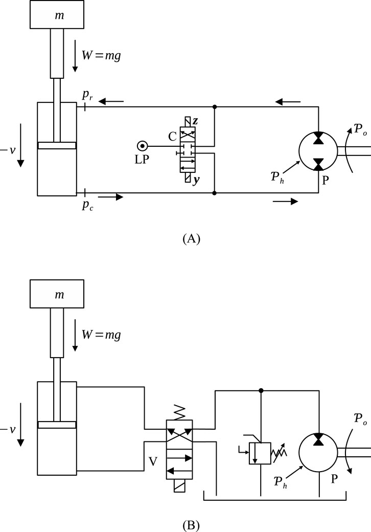
This paper focuses on pump-controlled actuators, where flow changes are produced exclusively at the pump (Costa and Sepehri, 2015). This is particularly important when the hydraulic circuit is closed, as in Figure 1A. In the figure, we observe that the cylinder can act both as an energy consumer (actuator) or as an energy supplier (pump). Hydraulic actuators, including hydraulic cylinders, can be controlled by adjusting the oil flow into and out of their chambers. Assuming fluid incompressibility, flow and piston velocity are directly proportional. The most common way to control speed is by gradually throttling the oil flow into or out of the cylinder chambers through directional and flow control valves. However, the added flow resistance significantly reduces the overall energy efficiency of the system. An alternative method is to change the oil flow directly at its source by adjusting the pump flow, either by altering its displacement or the pump shaft speed. This approach eliminates throttle losses and optimizes the system’s energy performance. These two methods of controlling the hydraulic actuator are generally described as “valve-controlled” and “pump-controlled” systems. When the cylinder becomes the energy supplier, the pump (P) operates as a hydraulic motor. The weight,
where
Focusing on the closed circuit shown in Figure 1A, we observe a directional valve (C) connecting each side of the cylinder to a low-pressure (LP) source. Valve C has been referred to as “compensation valve” (Costa and Sepehri, 2019), whose function is to match the flows coming from the cylinder to the flows going into and out of the pump. The control of valve C depends on the pressures on the piston and rod sides of the cylinder,
Figure 1B shows another circuit, now using a 4 × 2 valve (V) to control the cylinder. There is more energy dissipation between the cylinder and the pump due to the losses within valve V. However, the circuit is simpler, as no special design is needed to match the flows coming out of the cylinder to the flows coming into and out of the pump.
As mentioned before, in both cases, Figures 1A, B, the input power at the cylinder,
where
The power,
where
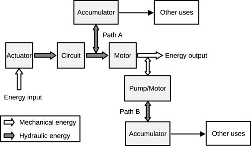
Power coming from the load is therefore transformed into hydraulic power and, subsequently, into mechanical power at the shaft. At both stages of power transformation, there may or may not be load energy recovery. In circuits where energy recovery is desired, two possible paths can be followed, as shown in Figure 2. In path A, an accumulator is connected in parallel to the hydraulic line coming from the cylinder, whereas in path B, mechanical energy flowing from the pump shaft is converted into hydraulic energy before loading the accumulator. Note that although two accumulators are shown in the Figure, only one is needed, depending on the path that has been chosen. In the first case, we circumvent the losses at the pump, thus allowing more energy to be recovered. The drawback is that the “hydraulic stiffness” of the circuit is reduced, creating a cushion effect that is undesirable in some situations. Energy stored in the accumulator can either be returned to the circuit or used for other purposes, as indicated in the Figure.
From this point on, we shall refer to circuits following path A as “Internal Storage Circuits” (ISCs), while those following path B will be referred to as “External Storage Circuits” (ESCs).
2 Internal storage circuits (ISC)
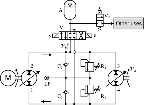
A typical ISC is represented in Figure 3, where the accumulator, A, communicates with lines 2–3 and 4–1 through a directional valve, V1, activated by two solenoids, y and z in an alternate manner. Valve V2, on the other hand, directs the hydraulic energy stored within A to “other uses,” through the activation of solenoid x. The figure shows a very generalized circuit, where variable displacement, fully reversible pumps are connected at both ends of the transmission. Some other elements are added to the circuit for sound operation. The relief valves, R1 and R2 are for pressure overshoot protection and the check valves, C1 and C2, operate as anti-cavitation valves. Both relief and check valves are connected to a low-pressure source, LP, which can be an oil tank or a low-pressure accumulator.
Because of the differential cylinder area in single-rod hydrostatic actuators, energy storage in hydrostatic actuators is not as popular as in hydrostatic transmissions. In fact, a lot of research has been directed to single-rod pump-controlled actuators through the years (Costa and Sepehri, 2019; Frankenfield, 1984; Hewett, 1994; Rahmfeld and Ivantysynova, 1998; Wang et al., 2012; Altare and Vacca, 2015; Calıskan et al., 2015; Heybroek et al., 2012; Karvonen, 2016; Williamson, 2010; Williamson and Ivantysynova, 2008; Imam et al., 2017; Stelson, 2011; Ivantysynova, 2008) and, although considerable progress has been made, these circuits are still subject to much research (see, for example, Ketelsen et al., 2019).
Examples of ISCs for hydrostatic transmissions can be found in (Pourmovahed et al., 1992a; 1992b; Hippalgaonkar and Ivantysynova, 2016a; 2016b; Bertolin and Vacca, 2021; Sprengel and Ivantysynova, 2013; Feng et al., 2023). Energy storage through accumulators have also been used in circuits with valve-controlled cylinders (Xia et al., 2018; Ranjan et al., 2020; Li et al., 2022; Casoli et al., 2016; Li et al., 2015; Lin et al., 2016; Li and Zhao, 2021). However, to the best of our knowledge, nothing has been published about hydrostatic actuators (pump-controlled actuators). In fact, only a single reference about an ESC (Wendel, 2002), besides an explanation of its operational principles (Costa and Sepehri, 2015) are all that can be found for pump-controlled actuators. The reasons for this have been explained at the beginning of this section: it is important to, first, solve the differential cylinder problem, before exploring load energy management.
One drawback of ISCs is that, whenever the accumulator is loading there is a considerable reduction of the effective bulk modulus of the circuit, reducing its hydraulic stiffness (Costa and Sepehri, 2015). Problems arising from this effect have been reported in hydraulic hybrid vehicles (Sprengel and Ivantysynova, 2013). Another drawback is the fact that the circuit pressure frequently needs to be risen to a higher level at the accumulator, so that it may be effectively used to help driving the load (Xia et al., 2018). Circuits with a variable-displacement motor at the load-end are advantageous, in this case, due to their capacity for changing the circuit pressure by adjusting the motor displacement (an example can be found in Hippalgaonkar and Ivantysynova, 2016a; 2016b).
We have seen that ISCs have the advantage of being able to store a greater fraction of the energy coming from the load. However, due to the difficulties concerning the construction of closed circuits with a single rod actuator, most of the applications so far have been applied to hydrostatic transmissions and valve-controlled actuators. In recent years however, some new developments have been made towards solving the differential area problem of the cylinder in hydrostatic actuators. In particular, we cite reference (Costa and Sepehri, 2019), where excellent and promising results were shown. In the following section, we briefly present the current research that has been carried out in the tele-robotics laboratory of the Mechanical Engineering Department, in the University of Manitoba, Canada, where a new proposal of an ESC is under investigation.
3 External storage circuits
The greatest difference between ISCs and ESCs is the smaller capacity for storing energy of the latter. This is simply because a fraction
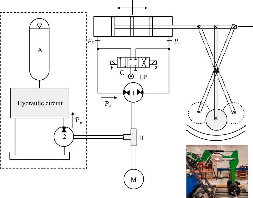
Figure 4 shows how an ESC, similar to one, currently mounted in the Tele-Robotics Laboratory of the Mechanical Engineering Department of the University of Manitoba. The test rig, in the laboratory, drives a cylinder attached to a dangling weight, as shown in the small picture at the low-right corner. The hydraulic circuit, therefore, can operate in a four-quadrant mode, with the load alternatively pushing and pulling the cylinder rod. In the circuit, an electric motor drives a pump, connected to the cylinder, and another pump which is responsible for loading the accumulator. A power hub, H, is responsible for splitting the power coming from the electric motor between the main pump and the accumulator pump. It also can divert power coming from the main pump, connected to the cylinder, to the pump connected to the accumulator. Means of mechanically engaging and disengaging the three shafts (clutches, for example) may be available, but are not shown in the figure for convenience.
The circuit in Figure 4 uses a novel ESC (Chithravelpillai, 2022; Chithravelpillai et al., 2024). Besides the excellent energetic efficiency in pumping quadrants, which is inherent to the main circuit configuration described by Costa and Sepehri (2019), preliminary experiments have shown that stored energy from the load during motoring quadrants has almost doubled the circuit efficiency in pumping quadrants, where the stored energy is reused to assist the electric motor, M (Chithravelpillai, 2022), as shown in Figure 5. Figure 5A shows the results (from both simulations and experiments) where no energy storage device was used and, therefore, no load energy could be recovered. Figure 5B shows efficiency for the same circuit incorporating an ESC. We see that the maximum efficiency has nearly doubled in quadrant III, where the stored load energy is reused to drive the load.
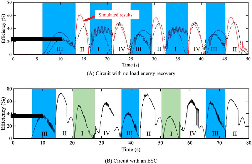
Figure 5. Efficiency comparison using experimental results: (A) circuit without load energy recovery; (B) circuit incorporating ESC as in Figure 4 (Chithravelpillai, 2022).
The ESC Pump 2 in Figure 4 may be substituted with a variable displacement pump, allowing for adjustment of the accumulator pressure. As it stands, the circuit enables the reuse of the accumulated energy to assist the cylinder in pumping quadrants. Variations of the circuit could include using the accumulated energy to drive an external device (“other uses” in Figure 2).
4 Conclusion
Reutilization of load energy in hydraulic circuits has already become a reality and it is increasingly necessary in a greener minded society. Pump-controlled, single-rod, actuators have come into play. This note has shown that there is great prospect and expectation that hydraulics will play a decisive role in energy recovery systems. Recent experiments carried out at the University of Manitoba have been very encouraging in this respect. Expectations are that in a near future, a fully functional circuit can be developed and industrialized. Until then, more experiments are expected, and more advances can be anticipated.
Data availability statement
The original contributions presented in the study are included in the article/Supplementary material, further inquiries can be directed to the corresponding author.
Author contributions
GC: Writing–original draft, Writing–review and editing. NS: Writing–review and editing.
Funding
The author(s) declare that financial support was received for the research, authorship, and/or publication of this article. This research was funded by NSERC (Natural Sciences and Engineering Research Council of Canada). Grant number: RGPIN 121353-2013.
Conflict of interest
The authors declare that the research was conducted in the absence of any commercial or financial relationships that could be construed as a potential conflict of interest.
The author(s) declared that they were an editorial board member of Frontiers, at the time of submission. This had no impact on the peer review process and the final decision.
Publisher’s note
All claims expressed in this article are solely those of the authors and do not necessarily represent those of their affiliated organizations, or those of the publisher, the editors and the reviewers. Any product that may be evaluated in this article, or claim that may be made by its manufacturer, is not guaranteed or endorsed by the publisher.
References
Altare, G., and Vacca, A. (2015). A design solution for efficient and compact electro-hydraulic actuators. Procedia Eng. 106, 8–16. doi:10.1016/j.proeng.2015.06.003
Bertolin, M., and Vacca, A. (2021). An energy efficient power-split hybrid transmission system to drive hydraulic implements in construction machines. ASME. J. Dyn. Sys. Meas. Control. 143 (10), 101005. doi:10.1115/1.4051035
Calıskan, H., Balkan, T., and Platin, B. E. (2015). A complete analysis and a novel solution for instability in pump controlled asymmetric actuators. ASME. J. Dyn. Syst. Meas. Control. 137 (9), 091008. doi:10.1115/1.4030544
Casoli, P., Riccò, L., Campanini, F., and Bedotti, A. (2016). Hydraulic hybrid excavator—mathematical model validation and energy analysis. Energies 9, 1002. doi:10.3390/en9121002
Chithravelpillai, B. (2022). “Energy storage and reutilization for a single-rod electro-hydrostatic actuator system,”. Winnipeg, CA: University of Manitoba. MSc Thesis. Department of Mechanical Engineering.
Chithravelpillai, B., Costa, G. K., Tomas, Z., and Sepehri, N. (2024). Energy storage and reutilization for a single-rod electro-hydrostatic actuation. U. S. Provisional Pat. Appl. Filed – March 14, 2023; Appl. No 63/490,093., Unite states Appl. no. 18/412, 851.
Costa, G. K., and Sepehri, N. (2015). Hydrostatic transmissions and actuators-operation, modelling and applications. Chichester - UK: Wiley.
Costa, G. K., and Sepehri, N. (2019). Four-quadrant analysis and system design for single-rod hydrostatic actuators. ASME. J. Dyn. Sys. Meas. Control. 141 (2), 021011. doi:10.1115/1.4041382
Feng, B., Xu, H., Wang, A., Gao, L., Bi, Y., and Zhang, X. (2023). A comprehensive review of energy regeneration and conversion technologies based on mechanical–electric–hydraulic hybrid energy storage systems in vehicles. Appl. Sci. 13, 4152. doi:10.3390/app13074152
Frankenfield, T. C. (1984). “Using industrial hydraulics,”. Cleveland - OH: Hydraulics and Pneumatics Magazine.
Hewett, A. J. (1994). Hydraulic circuit flow control. University of British Columbia. Vancouver- BC. Canada. U.S. Patent No. US5329767A.
Heybroek, K., Vael, G., and Palmberg, J.-O. (2012). “Towards resistance-free hydraulics in construction machinery,” in The eighth international fluid power conference (Dresden, Germany, Mar: IFK), 2, 123–138.
Hippalgaonkar, R., and Ivantysynova, M. (2016a). Optimal power management of hydraulic hybrid mobile machines—Part I: theoretical studies, modeling and simulation. ASME. J. Dyn. Sys. Meas. Control. 138 (5), 051002. doi:10.1115/1.4032742
Hippalgaonkar, R., and Ivantysynova, M. (2016b). Optimal power management of hydraulic hybrid mobile machines—Part II: machine implementation and measurements. ASME. J. Dyn. Sys. Meas. Control. 138 (5), 051003. doi:10.1115/1.4032743
Imam, A., Rafiq, M., Jalayeri, E., and Sepehri, N. (2017). Design, implementation and evaluation of a pump-controlled circuit for single rod actuators. Actuators 6 (10), 10–15. doi:10.3390/act6010010
Ivantysynova, M. (2008). “Innovations in pump design - what are future directions?,” in Proceedings of the 7th JFPS international symposium on fluid power (Toyama, Japan), 60–64.
Karvonen, M. (2016). Energy efficient digital hydraulic power management of a multi actuator system. Tampere, Finland: Tampere University of Technology. Ph.D. Thesis.
Ketelsen, S., Padovani, D., Andersen, T. O., Ebbesen, M. K., and Schmidt, L. (2019). Classification and review of pump-controlled differential cylinder drives. Energies 12, 1293. doi:10.3390/en12071293
Li, J., and Zhao, J. (2021). Energy recovery for hybrid hydraulic excavators: flywheel-based solutions. Automation Constr. 125, 103648. doi:10.1016/j.autcon.2021.103648
Li, L., Zhang, T., Wu, K., Lu, L., Lin, L., and Xu, H. (2022). Design and research on electro-hydraulic drive and energy recovery system of the electric excavator boom. Energies 15, 4757. doi:10.3390/en15134757
Li, W., Wu, B., and Cao, B. (2015). Control strategy of a novel energy recovery system for parallel hybrid hydraulic excavator. Adv. Mech. Eng. 7, 10. doi:10.1177/1687814015613769
Lin, T., Huang, W., Ren, H., Fu, S., and Liu, Q. (2016). New compound energy regeneration system and control strategy for hybrid hydraulic excavators. Automation Constr. 68, 11–20. doi:10.1016/j.autcon.2016.03.016
Pourmovahed, A., Beachley, N. H., and Fronczak, F. J. (1992a). Modeling of a hydraulic energy regeneration system: Part I - analytical treatment. ASME. J. Dyn. Sys. Meas. Control. 114 (1), 155–159. doi:10.1115/1.2896497
Pourmovahed, A., Beachley, N. H., and Fronczak, F. J. (1992b). Modeling of a hydraulic energy regeneration system: Part II - experimental program. ASME. J. Dyn. Sys. Meas. Control. 114 (1), 160–165. doi:10.1115/1.2896498
Rahmfeld, R., and Ivantysynova, M. (1998). “Energy saving hydraulic actuators for mobile machines,” in The first bratislavian fluid power symposium, casta pila, Slovakia, june 2–3, 47–57.
Ranjan, P., Wrat, G., Bhola, M., Mishra, S. K., and Das, J. (2020). A novel approach for the energy recovery and position control of a hybrid hydraulic excavator. ISA Trans. 99, 387–402. doi:10.1016/j.isatra.2019.08.066
Sprengel, M., and Ivantysynova, M. (2013). “Investigation and energetic analysis of a novel hydraulic hybrid architecture for on-road vehicles,” in Proceedings of the 13th Scandinavian International Conference on Fluid Power, SICFP2013, Linköping, Sweden, June 3–5, 87–98. doi:10.3384/ecp1392a9
Stelson, K. A. (2011). “Saving the world’s energy with fluid power,” in The eighth JFPS international symposium on fluid power (Okinawa, Japan: JFPS), 1–7.
Wang, L., Book, W. J., and Huggins, J. D. (2012). A hydraulic circuit for single rod cylinders. ASME. J. Dyn. Syst. Meas. Control. 134 (1), 011019. doi:10.1115/1.4004777
Wendel, G. R. (2002). “Hydraulic system configurations for improved efficiency,” in Proceedings of the 49th National Conference on Fluid Power – NCFP, USA, 567–573.
Williamson, C. (2010). Power management for multi-actuator mobile machines with displacement controlled hydraulic actuators. West Lafayette: Purdue University. Ph.D. Thesis.
Williamson, C., and Ivantysynova, M. (2008). Pump mode prediction for four quadrant velocity control of valveless hydraulic actuators. Seventh JFPS Int. Symposium Fluid Power, Toyama, Jpn. Sept 15–18, 323–328.
Keywords: hydraulic circuits, hydraulic accumulators, hydraulic energy storage, hydrostatic actuators, pump-controlled actuators
Citation: Costa GK and Sepehri N (2024) Energy management in pump-controlled actuators. Front. Mech. Eng. 10:1453739. doi: 10.3389/fmech.2024.1453739
Received: 23 June 2024; Accepted: 22 November 2024;
Published: 06 December 2024.
Edited by:
Valentin L. Popov, Technical University of Berlin, GermanyReviewed by:
Davide Di Battista, University of L’Aquila, ItalyShahrokh Hatefi, Nelson Mandela University, South Africa
Copyright © 2024 Costa and Sepehri. This is an open-access article distributed under the terms of the Creative Commons Attribution License (CC BY). The use, distribution or reproduction in other forums is permitted, provided the original author(s) and the copyright owner(s) are credited and that the original publication in this journal is cited, in accordance with accepted academic practice. No use, distribution or reproduction is permitted which does not comply with these terms.
*Correspondence: Gustavo Koury Costa, Z3VzdGF2b2tvdXJ5QHJlY2lmZS5pZnBlLmVkdS5icg==
 Gustavo Koury Costa
 Nariman Sepehri