
94% of researchers rate our articles as excellent or good
Learn more about the work of our research integrity team to safeguard the quality of each article we publish.
Find out more
ORIGINAL RESEARCH article
Front. Mech. Eng., 12 February 2024
Sec. Solid and Structural Mechanics
Volume 10 - 2024 | https://doi.org/10.3389/fmech.2024.1360590
 Aditya Verma1
 Ravi Shankar2
 Ameer Malik Shaik2,3
 B. Veera Siva Reddy3*
 C. Chandrasekhara Sastry3*
 Nizmi Shaik4
 Sachin Salunkhe5,6*
 Robert Cep7
 Emad Abouel Nasr8
Introduction: This study presents a comprehensive design and analysis of a 300L steel fuel tank intended for heavy off-road vehicles. The design process integrates numerical simulations and experimental investigations to optimize the tank's performance and durability under various operating conditions.
Methods: The design methodology involves CAD model optimization, numerical analysis setup, and experimental validation. CAD model optimization simplifies the tank geometry while retaining structural integrity. Numerical analysis setup includes defining boundary conditions, meshing strategies, and simulation parameters. Experimental validation entails testing the tank under dynamic loading conditions to assess its structural response.
Results: Numerical simulations reveal insights into stress distribution, deformation behavior, and fluid dynamics within the tank. Experimental tests confirm the numerical predictions and provide valuable data for model validation. Key results include stress concentrations in critical areas, deformation patterns under different loading conditions, and fluid flow characteristics.
Discussion: The integrated approach combining numerical simulations and experimental tests offers a comprehensive understanding of the fuel tank's behavior. Findings highlight areas for design improvement, such as reinforcement of stress-prone regions and optimization of fluid flow dynamics. The study contributes to enhancing the performance, reliability, and safety of fuel tanks for heavy off-road vehicles.
Cross country vehicles, specifically tracked, off-road, vehicles are important in various industries such as construction, mining, defense, and agriculture. These vehicles are designed to traverse harsh and challenging terrains, and therefore must meet strict safety and performance requirements to ensure their efficient and reliable operation. These vehicles consist of complex sub-assemblies among which fuel systems and tanks are of great importance. Steel is a commonly used material for the fuel storage tanks of these vehicles due to its durability, strength, and ease of production. Alternatively, high density polyethylene or fiberglass composite are also used for constructing fuel tanks.
The design and analysis of steel fuel tanks for tracked off-road vehicles is a complex process that involves a thorough understanding of the material properties, loading conditions, and safety requirements. This research paper provides an overview of the design and analysis of steel fuel tanks for cross country vehicles, including the materials, fabrication methods, and analysis techniques used. The paper will also discuss the various codes and standards that govern the design and construction of fuel storage tanks for off-road vehicles, and the testing and inspection procedures used to ensure the safety and performance of these tanks.
Cameron (Rout et al., 2022) highlighted that the recent shift in alternative fuel has introduced alternatives like battery and hydrogen powered vehicles. But for remote operations and high load requirements, diesel powered powerpacks are preferred. All the new powertrains, namely, electric and hydrogen are still dependent on the production of renewable energy sources to reduce carbon footprint. Additionally, there has been a striking development in the production of carbon fuels through sunlight, and carbon dioxide from the atmosphere resulting in carbon neutral Hydrocarbon fuels (Schäppi et al., 2022). These new methods will help in sustainable development without changing the present infrastructure.
For designing robust, safe, and high-quality fuel tanks various analyses can be carried out with the help of modern-day finite element analysis methods. This caters to near-net development by taking all factors for development by curtailing the financial burden. In order to store volatile fuel safely, a pressurized vessel is necessary. Nevertheless, the vessel is susceptible to damage caused by an increase in internal pressure, which may surpass the designated operating pressure or critical pressure. To prevent failures, it is essential to conduct finite element method analysis to identify critical stresses and study potential deformations in the vessel (Annamalai et al., 2021).
Yang Gao (Gao et al., 2018a) analyzed the fuel tank for an armored vehicle for static and dynamic loading, which aided in optimizing the tank design. The FEM analysis technique for static and fatigue loading accurately pointed out design flaws using a stress distribution diagram. Areas where major loads will be transferred to welds were identifiable. Guidance on the installation of the tanks and improving the service life of tanks for armored vehicles was given. Ţălu (Ţălu and Ţălu, 2018) designed and analyzed a paralepipedic fuel tank under pressure and varying temperatures, which demonstrated that Von Mises stresses decreased with a rise in temperature and then started increasing after 40°C. It was observed, that the linear deformation factor attenuated with the rise in temperature continuously.
For passenger vehicles automotive industry standard 095 is followed for road worthiness, which holds a compulsion before utilization. A high-speed vehicle which is primarily used for cross country applications, will require additional robust testing parameters defined initially keeping the performance requirements in mind. Two tests, a hydraulic test and an overturn test are carried out on metallic tanks, keeping in the purview of the operator and various terrains the vehicle is availed (kumaran et al., 2023).
Welding is the primary method of joining different steel components. Hence, it is important to predict the strength of welded joints under static and dynamic loading conditions. Gheorghe Asachi (Heinemann et al., 2021) used the FEM method with different types of mesh elements to predict the stress concentration and deformation. The tetra linear elements were found to be more accurate as compared to tetra quadratic elements in predicting Von Mises stress data. In his welding research, Abubkr H (Hemer et al., 2020) found that when joining the base metal with a weld metal, the weld metal exhibits higher yield and tensile strength. The FEM results of the Charpy impact test showed higher crack lengths as compared to experimental results. Also, the hardness values were highest at the heat affected zones and welded metal has slightly higher values than base metal. This shows a greater risk of failure of welded joints during cyclic loading and indicates a need to predict and study intricately about weldment fracture.
Banagar (Banagar, 2015) predicted the stress concentrations and deformations under self-loading and full load conditions for a pressure vessel. The joint efficiency is assumed as 0.7 and stress concentrations were highlighted at support and nozzle regions. Hence, a pressure vessel is subjected to self-load, external loads, and thermal loads, which may cause failure instantaneously or even due to fatigue loading. There are various welding techniques available, but welds produce heat affected zones, which in turn hardens the metal around the joint and promotes cracks and rusting. Abbasi (Abbasi and Salmani, 2008) and Basak (Basak et al., 2016) studied different welding processes to certain that manual brazed joints offer the best results for corrosion resistance. Also, the anti-corrosion coating should have a higher melting point than the welding operation temperature to ascertain the long life of the steel welded fuel tanks.
Another type of physical change inside the fuel tank happens due to the excitation of free liquid volume, due to external accelerations. Primarily during accelerating, stopping, and turning the liquid changes its shape which may result in incorrect fuel level readings, fuel starvation to the engine, and structural loading on the vehicle itself. As the analytical solutions for computational fluid dynamics are very difficult, the numerical approach is the preferred method for sloshing analysis. In recent years, CFD programs have become a prominent tool to understand liquid and gas flow behavior. It can also aid in predicting the transfer of heat, mass, phase change, chemical reaction, mechanical movement, and stress deformation of structural components (Zawawi et al., 2018).
Various research methods for different types of tank shapes undergoing varied types of excitation have been studied in recent times. With the advancement in computer hardware and software technology, CFD solutions have become easier to solve with closer to real-net values. Frosinia, Zhang, Enhui, Ren He, and Kim (Frosina et al., 2018; Kim et al., 2020; Zhang et al., 2020; Zhang and He, 2020) have individually done research on different tank designs accompanied by different shapes, sizes, and designs of baffles. But to the best of the authors’ knowledge, very little work has been carried out for the design and analysis of steel fuel tanks for military off-road vehicles. With low variation and appropriate tool methods, analysis of 300 times fuel tank is performed in this work, for a free liquid surface boundary region.
The initial steps consist of deciding the storage capacity as per defense standards and range requirements, along with the material of construction which will be steel, aluminum, HDPE, or composite. The shape of the tank is primarily decided by understanding the placement of the tank in the vehicle assembly. The tank will be accompanied by the general sub-components such as filters, strainers, drain plug, pump, etc. as per specific requirements.
The tank will be undergoing testing before-hand as per international and automotive standards (Everyspec, 2007; Everyspec, 2008; Indian Standard, 2023b; Indian Standard, 2023a; kumaran et al., 2023) for safety and performance criteria. The inspection and maintenance of the tank should be easy throughout its life of use. This study is focused on a comprehensive analysis of multiple parameters related to the structural and operational capability of a diesel fuel tank, whose detailed information is tabulated in Table 1.
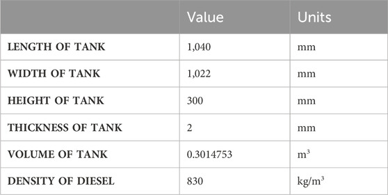
TABLE 1. General information of tank.
The fuel tank is formed into a shell using 2 mm stainless steel plates through sheet metal operations. The complete flowchart is visualized in Figure 1. The fuel tank outer structure consists primarily of three components, one outer shell, and two side closing plates, and three interior baffles which will also work as stiffener or support structures as shown in Figure 2. The choice of 2 mm thickness sheets due to its availability in the manufacturing domain requirement and act as a strong barrier to withstand the loads without exceeding the weight limit of 71 kg of the fuel tank at the design stage.
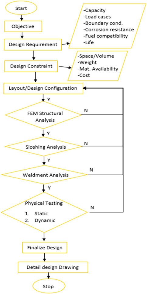
FIGURE 1. Preliminary fuel tank design flow chart.
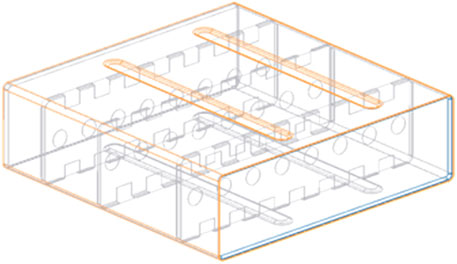
FIGURE 2. CAD model of Tank.
The properties of steel, with a density of 7,850 kg/m3 and Elastic modulus of 1.93 × 10¹¹ Pa (Indian Standard, 2008) were used for defining structural characteristics. Two general grades of stainless steel were considered for constructing the pressure vessel as per IS 6911 (1992) and IS 513 (2008). Their material composition and tensile strength are as per Table 2 (Indian Standard, 1992; Indian Standard, 2008).

TABLE 2. Composition and strength of 304 S2 steel as per IS 6311 and CR2-D steel as per IS 513.
After defining a preliminary design and material, the tank is tested for hydraulic pressure as per AIS 095 for structural rigidity, then for sloshing phenomena due to external excitation, and finally, weldment analysis for weak spots under hydraulic loading. Additionally, the fatigue life of different components is estimated, formulated, and summarised for review and testing of the prototype tank.
In our specific fuel system, the tank in consideration is connected to a high-capacity nose tank, which at full capacity will exert a pressure head of 1 m on the analyzed tank. There is no pumping system attached in between, and the two tanks are connected using a 16 mm diameter pipe, the flow of the fuel is primarily due to gravitational pull.
Hence, a static pressure head of 1 m of diesel fuel is considered the maximum operating pressure of the tank at full capacity. This pressure will be used for the actual loading of the tank at 8,142.3 Pa. For dynamic loading conditions, the testing pressure will be 30,000 Pa as per AIS 095 under which the tank may deform permanently, but not be cracked or lead to leakage of any fuel for which observations must be made after the tests (kumaran et al., 2023). This corresponds to the structural analysis of the tank.
The tank is secured from all six sides and held tightly in place with the help of multiple studs, rubber straps, and adjacent walls. This arrangement will allow for an easy replacement. These supports will induce higher stresses on the tank due to normal reactions. Along with stresses, maximum deformation is also measured to predict any interference with nearby components.
The overall tank comprises various components, and to enhance the efficiency of numerical analysis, certain assumptions are integrated into the design. The tank model for CAD optimization follows these assumptions (Du, 2017; Gao et al., 2018b).
1. Exclusion of Internal Components: Holes and pipes within the fuel tank are disregarded, focusing solely on the rigid and structural components.
2. Neglect of Seam and Spot Welds: The influence of seam and spot welds between plates is not considered; instead, the entire fuel tank is treated as an integral enclosure with uniform thickness.
3. Applied Pressure Direction: The overall pressure is exclusively directed outward onto the internal walls of the tank, with no consideration for the impact on internal components.
The comprehensive tank model is developed using PTC Creo Parametric 7.0.5.0. This optimized approach ensures an effective numerical analysis while simplifying the model to key structural elements, contributing to the overall robustness of the study.
The constant pressure analysis is conducted using the static structural module in Ansys 2022 R1. The optimized CAD model is imported into DesignModeler, where the mid-surface of the sheet metal parts is generated to facilitate simplified volume meshing. To ensure a robust simulation, bonded connections are defined at weld joints between tank parts, and appropriate boundary conditions are established.
Key Numerical Analysis Setup Details.
• Analysis Method: Constant pressure analysis is performed utilizing the static structural module within Ansys 2022 R1.
• Simulation Duration: The time of simulation is conducted for a duration relevant to achieving accurate and meaningful results.
• Meshing Strategy: The mid-surface approach is employed for sheet metal parts to streamline volume meshing complexities.
• Contact Definitions: Bonded connections are specified at welding joints to simulate the structural behavior of the tank parts accurately.
• Boundary Conditions: Detailed specifications are provided to ensure the simulation accurately reflects real-world conditions and interactions.
By incorporating these details, a more comprehensive understanding of the intricacies involved in the numerical analysis setup will be achieved. Meshing is done in Ansys Mesher, the mesh has been optimized initially and then checked for convergence issues for critical areas. The mesh is said to converge if the change in results is less than 5%. The final mesh contains 95,574 nodes and 90,498 elements with a percent change of 3.54% in terms of stress and 0.25% for deformation. Hence, the results are said to be converging and are availed for final outcomes.
The final results were evaluated for equivalent stress and total deformation in the parts. The dynamic loading conditions for the tank analysis involve subjecting the tank to an acceleration of 0–32 kmph within a time span of 6 s. This translates to a general acceleration value of 1.48 m/s2 for the initial 6 s from a state of rest. The emphasis is placed on analyzing the time aspect to assess potential fuel starvation at the pump inlet inside the tank and to quantify the forces exerted on the tank walls in the direction of excitation.
The detailed parameters of the dynamic loading conditions include.
• Acceleration Profile: 0 to 32 kmph in 6 s: Constant acceleration profile for initial which is 1.48 m/s2 6 s
• Acceleration Value: 1.48 m/s2 for the initial 6 s.
• Objective: Evaluate the impact on the pump inlet, observe fuel starvation, and quantify forces on the tank walls during the acceleration period.
By providing these additional details, aiming to offer a clearer understanding of the dynamic loading conditions applied during the tank analysis.
i. For actual loading conditions
• The actual loading condition shows fairly, less stresses in the range of 160–202 MPa which is concentrated on the baffles where they are joined with the corrugated side walls of the tank as shown in Figure 3.
• The tanks show deformations mainly in the regions of minimal supports from baffles and side walls of the tank, in the range of 1.1 mm–1.597 mm.
ii. For dynamic loading conditions
• For the dynamic loading conditions, the tank shows a high concentration of stress at the top face where the baffles are joined near the side walls of corrugations at 431.4 MPa as highlighted in Figure 4.
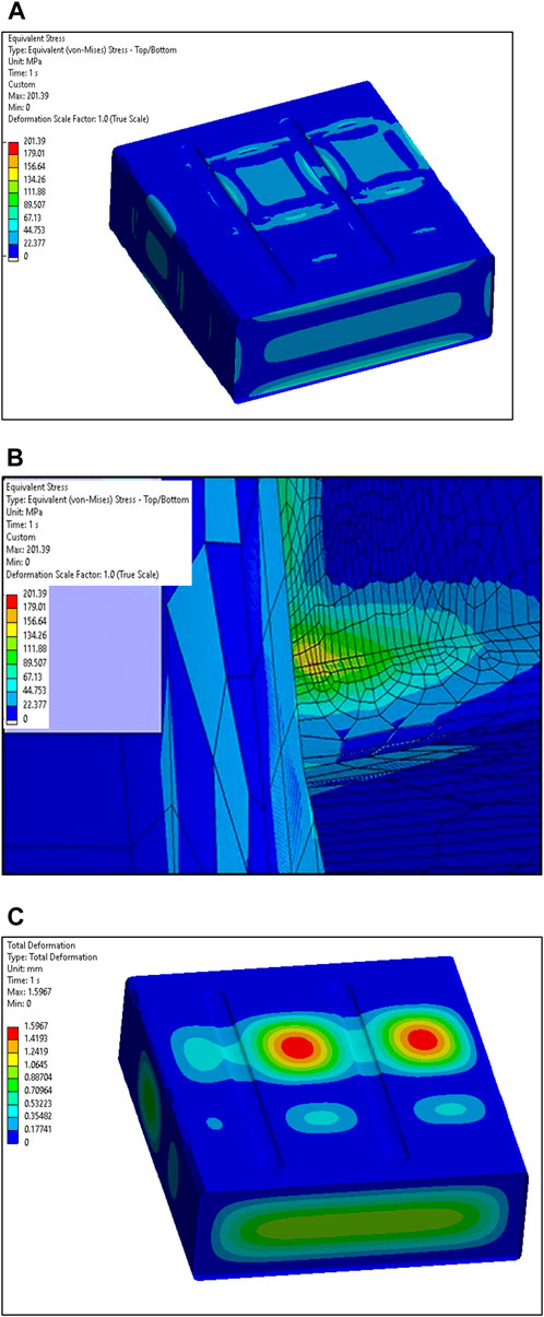
FIGURE 3. Tank under actual loading (A) Equivalent Stress, (B) Maximum Equivalent Stress, (C) Total deformation.
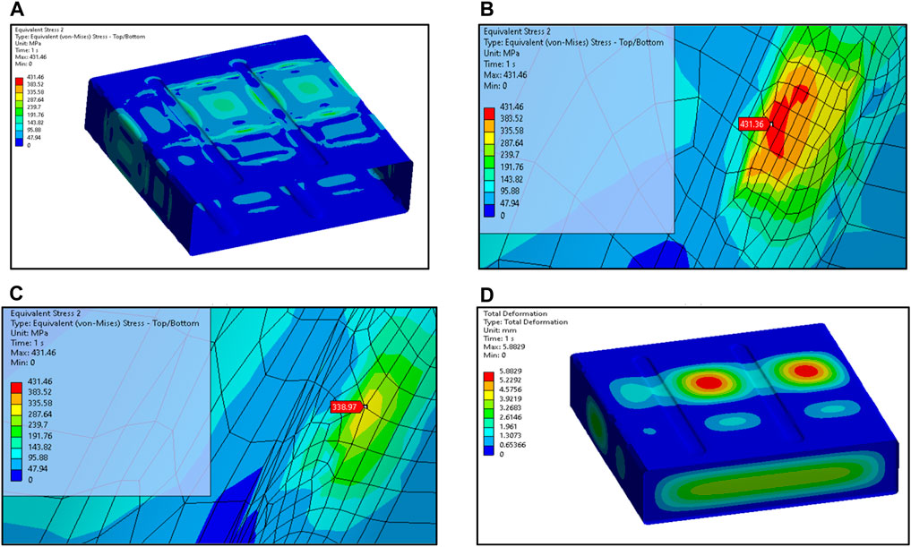
FIGURE 4. Tank under dynamic loading (A) Equivalent Stress, (B) Maximum stress region on the tank shell, (C) Second maximum stress region on the tank shell, (D) Total deformation.
In other areas the stresses are below 270 MPa.
• The tank shows high deformation in areas where stiffener support is not present. A maximum of 5.88 mm of deformation is observed in the max location. The other three areas show deformation of between 4 and 5.8 mm.
Note: A thorough investigation into mesh sensitivity has been conducted. The mesh has been refined in critical areas, and sensitivity analysis has been performed to ensure the reliability of the reported maximum stress value in Figure 4B. These measures aim to enhance the robustness of the findings and provide more accurate insights into the tank’s behavior under dynamic loading conditions.
The results show high stress and deformation in areas of minimal support from the overall tank geometry, which is expected. As the stress values are below the tensile yield strength of 440 MPa for 304S2 steel, the design can be carried forward. It is expected that in further analysis (i.e., weldment analysis) due to the addition of welds, the tank shell will suffer lesser stress concentration under dynamic loading conditions. Then CR2-D material can also be considered at the final stages.
The fuel stored inside the tank undergoes various external excitations during the vehicle operation primarily during accelerating, braking, and turning. Accompanied with cross country traversal the problem becomes more complex. As the liquid volume reacts to the external forces, for large tanks effects like variation in the center of mass and structural loading on tank walls happen and thus affect the steering and braking performance of the vehicle. To counter the problem, baffles are used in the form of suppression devices of various shapes and sizes inside the tanks. This helps by reducing the pressure and moments of liquid mass. The tank shape and liquid-free surface crucially define the sloshing characteristics.
The mathematical model to represent the sloshing phenomena in terms of analytical equations is given by conservation of mass, momentum, and energy. The topic is only introduced here, as it is vastly discussed in the references. The Volume of Fluid (VOF) method developed by Hirt and Nicholas (Hirt and Nichols, 1981) is quite renowned for capturing liquid-free surfaces. The method represents properties of either one phase or a mixture of phases depending on volume fraction. The ratio of the volume of phase in the cell to the volume of the cell is defined as volume fraction. The volume fraction will either be 0 (empty), 1 (fully filled) or in between 0 and 1 (a mixture of air and liquid).
VOF equation
With,
Where
The fluid is assumed as incompressible, and surface tension and cavitation are neglected. The incompressible Navier-stokes equation is used to describe the sloshing behavior of fluid in general which is based on the conservation of mass and momentum
Where bi is the body force,
The flow is considered to be dominantly turbulent, and irrotational which increases the dissipation of energy, heat transfer, and drag. The turbulent k-ε model proposed by Comini, G., and S. Del Giudice (Comini and Del Giudice, 1985) is a very popular turbulent model for industrial applications of CFD. Turbulent kinetic energy k and dissipation rate ε are used to find Reynolds’s stress. The transport equations are given by
Where
The complete fluid volume is defined in PTC Creo for the tank with (Figure 5A) and without baffles (Figure 5B). The pump design is simplified to reduce the complexity of the mesh.

FIGURE 5. (A) - Fluid Volume without baffles. 9 (B) Fluid volume with baffles.
The model is compared to an internal fuel tank with a 25% fill level, which has been excited as per the acceleration of 0–32 kmph in 6 s. Hence, a general acceleration value of 1.48 m/s2 for the first 6 s from rest. Importance is given to analyzing the time to check if the pump inlet inside the tank is ever starved of fuel and how much force is exerted on the walls of the tanks in the direction of excitation. The case is set up in Ansys Fluent 2022 R1, meshing is done in Ansys Mesher with a maximum element size of 100 mm as tetrahedron elements with the following mesh quality as per Table 3.
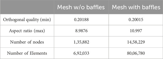
TABLE 3. CFD Mesh statistics.
The multiphase VOF model for viscous k-omega SST turbulent model is defined for solving. With a total time of 6 s, a non-iterative time advancement scheme is defined with adaptive time advancement. The smallest time step size is defined as 0.0001. To comprehensively examine the forces acting on the tank walls in the direction of acceleration, the setup includes defining visual representations for insights into the fluid dynamics, flow patterns, and the impact of forces on the tank walls throughout the simulation period.
After analyzing the result, and force plot shown in Figure 7A, the external acceleration generates 3 waves, which splash at time periods of 1 s, 3.3 s, and 5.7 s hence, with high pressure generation on the walls of the tank in the opposite direction of acceleration due to liquid inertia. The first wave exerts a maximum force of the order of 150 N and the other two waves of the order of 125 N, which is generally termed splashing phenomena inside the tank.
The significance of the liquid free surface beneath the pump becomes apparent during dynamic motions, as there is a risk of fuel starvation for the pump. When examining the worst-case scenario for the fuel level inside the tank, the isometric and side views emphasize a critical moment at 1.06513 s, as illustrated in Figure 6A. At this point, the pump inlet is dangerously close to being exposed to air.
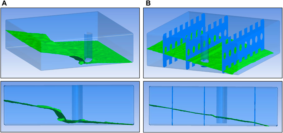
FIGURE 6. Liquid Free surface ISO and side view at (A) 1.06513 s for tank without baffles, (B) 2.49428 s for tank with baffles.
The Force plot for the tank with baffles in Figure 7B, shows waves splashing on the walls at 1.75 s, 2.4 s, and 5.2 s. But the forces on the walls are of a lower magnitude of 100 N for the first two and 96 N for the third splash.
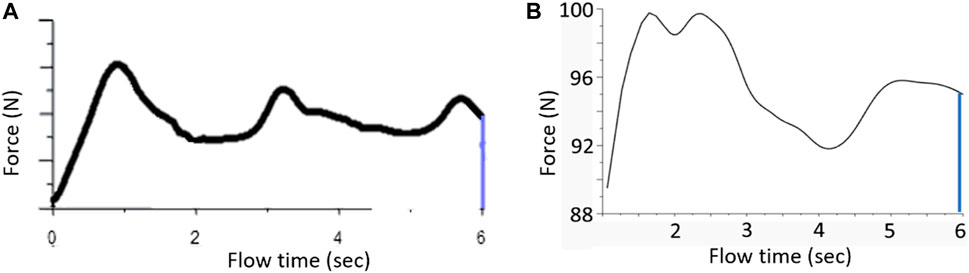
FIGURE 7. Lateral force on tank wall during excitation (A) with baffles. (B) Lateral force on tank wall during excitation with baffles.
Hence, the addition of baffles has reduced the peak force transferred to the tank walls by 33%. The general load on the walls is in the range of 75 N–100 N due to the pressure head, therefore the turbulent kinetic energy generated inside the tank is of not much great concern. Additionally, the worst condition for the liquid free surface occurred at 2.49 s during which the condition was like as per Figure 6B.
As the pump is active during vehicle acceleration, fluid is sucked into the pump, there will be air sucked by the pump in the case of the tank without baffles. The baffles have helped greatly in reducing internal excitations. Hence, the design of baffles has aided the performance of the tank.
The weldment analysis of steel fuel tanks allows us to identify areas of weld failures during actual and dynamic loading. The general seam weld strength depends on the weld design, process, and materials. Although generally there is a certain level of defect in the welds, which is considered a weld quality factor during calculations, the welds are assumed to be of the same strength as base material in our case.
An updated design model from the maximum internal pressure analysis introducing the various seam welds has been enlisted as solid parts in the assembly as showcased in Figure 8A. These welds will be replaced with the bonded connections in between parts holding them together and the corresponding connections in between various parts will be removed.
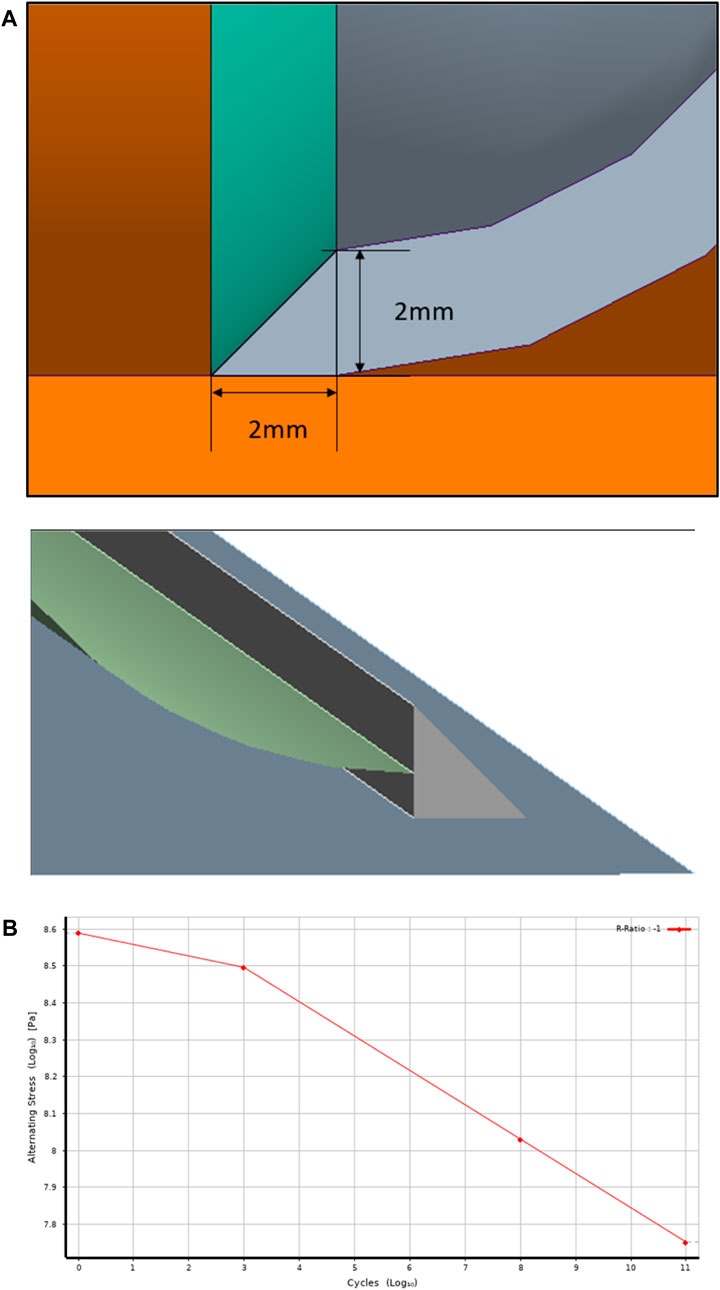
FIGURE 8. (A) Weld CAD solid geometry. (B) S-N reference graph for fatigue analysis.
The welds are tested for the same working pressure of actual loading at 8,142.6 Pa and a dynamic load condition of 30,000 Pa. Additionally, fatigue analysis of the tank with respect to fatigue loading under 120% of the working pressure values is carried out, this helped in predicting the minimum life cycle of various joints and parts. Fatigue is a major concern in the design and analysis of steel fuel tanks, as repeated loading can cause the welded joints to fail over time. A weld strength fatigue numerical analysis is essential to ensure the reliability and safety of the fuel tank under repeated loading conditions.
As indicated in Figure 8B, a close-to-net similar material from the Ansys fatigue material database, hot rolled high strength low alloy steel, is used as input characteristics for evaluation of cyclic loading failure for steel to predict the life of various components.
The mesh size is defined while considering the size of welds, the mesh has been refined and then verified for convergence issues by refining it. A change in result of less than 5% has been set as the limit of convergence. The convergence study is then carried out for which the change in results for stress is 1.63% and deformation of 0.84%. Observing the miniscule change in results 10 mm of global size with 2.5 mm of body and face sizing at contacts is chosen for results. The mesh contains 2,82,306 nodes and 2,13,972 elements.
The results were analyzed for equivalent stress and total deformation of parts for both, actual and dynamic loading conditions.
i. For actual loading conditions
• Under normal loading conditions, the tank undergoes stress concentrations at the welds with minimum supports from nearby baffles and corrugations as shown in Figure 9A.
• The welds undergo a maximum stress of 173.64 MPa as in Figure 9B, at other locations it is less.
• The major deformation is in the areas of minimum supports from side walls, corrugations, and baffles. Which is of the order of 1.34 mm as shown in Figure 9C.
ii. For dynamic loading conditions
• Under the conditions, the tanks show high deformation where minimum support from baffles and corrugations are present. With an upper limit of 4.95 mm.
• The side plates show a maximum bulging of around 3.4–3.6 mm.
• The stress concentration is maximum around the areas of weld surrounding the areas of max deformation and below 286 MPa in the tank shell as shown in Figures 10A, B.
• The first and second highest stresses on the tank shell are of the order of 286 MPa (Figure 10C) and 276 MPa (Figure 10D).
• The internal welds have suffered maximum stresses up to 639 MPa, which may result in the breaking of the welds under dynamic loading conditions as shown in Figure 10E.
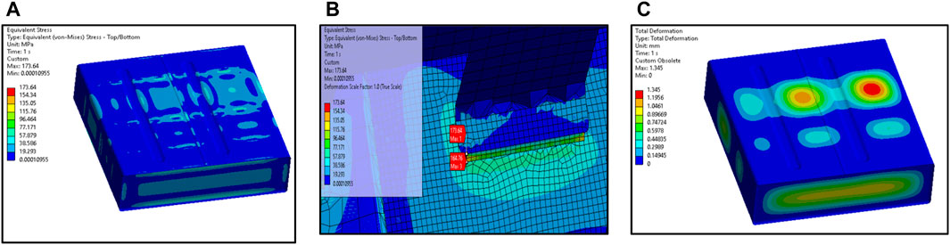
FIGURE 9. Tank stresses under actual loading. (A) Top view, (B) Stress concentration, (C) Top view of tank and weld deformation.
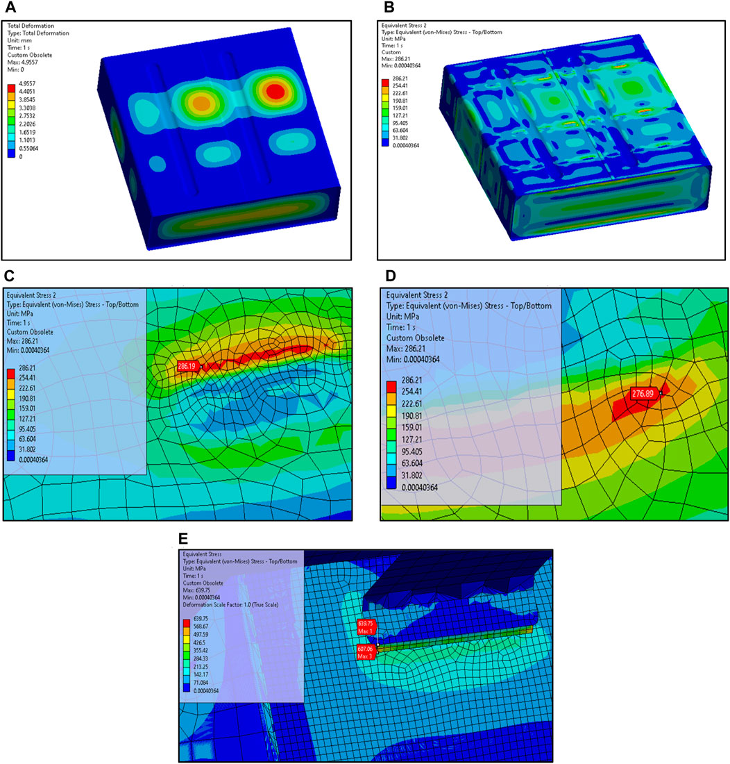
FIGURE 10. (A) Top view of tank stresses under dynamic loading, (B) view of tank, (C) major stress on tank shell, (D) major stress on tank shell, (E) stress concentration of welds.
Fatigue is the major cause of failure for parts undergoing loading. The analysis will help in predicting the life of the components. During maintenance and fault analysis these analysis results will help in deciding important areas to look first for signs of crack generation or failure. A similar model with the change in load values of 120% of the actual loading condition, which will be 9,770.76 Pa is assumed to predict the fatigue life of various components. The Ansys fatigue tool is used to predict fatigue life and damage data.
The loading conditions are set to be zero-based, where the loads are not fully reversed but periodically move from zero to a maximum value and then back to zero. The mean stress theory implemented is Gerber which is generally used for ductile materials. The fatigue strength factor is set as 1, which means the strength of loads will not diminish with the number of cycles.
The maximum equivalent stress is of the order of 211.15 MPa at 120% of the actual load, which is below the yield strength of the material. The tank is supposed to work for a minimum of 105 load cycles. The result shows the minimum life of the maximum stressed components at 5.2286e+7 cycles in Figure 11 with other areas having higher life cycles.
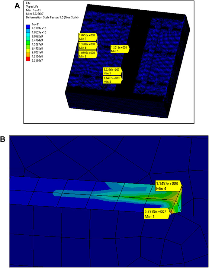
FIGURE 11. (A) Minimum life of various tank welds under cyclic loading, (B) Lowest weld life view under fatigue loading.
The results are coherent with our earlier analysis results, that the welds with minimum support from nearby components will be deformed the most, resulting in early failure of the welds in those locations.
It is important to verify the simulation results through prototype development and testing as per specified loading conditions for comparison. The prototype was developed using the same 2 mm thickness IS 513D material, the outer sheets were joined together using the tungsten inert gas (TIG) welding process. The inner baffles were welded using the shielded metal arc welding (SMAW) technique. The final weight of the tank without the internal pump and other devices and without any liquid content is 67.8 kgs, which is very close to the predicted weight of 71 kgs earlier. The testing equipment is designed as per the requirement of testing parameters.
The pressure test will be carried out before the tanks are painted, and thoroughly washed in clean water. All outlets and thread connections shall be sealed off with a treaded plug or with a blind socket except one where a pressure gauge is fitted. The tank shall be pressurized gradually to the specified pressure and held for 5 min.
Figure 12A shows the prototype tank manufactured, the final operations of surface finishing and painting will be done after the test results are verified. The final tank is as shown in Figure 12E. For generating maximum pressure inside the tank, a simple device that comprises a hand operated pump, pumping water from the reservoir tank fixed below it. The outlet from the pump is connected to a pressure gauge which will display the pressure built up in the tank as shown in Figure 12B. The gauge has a least count of 0.1 kg/cm2 with maximum pressure measurable up to 7 kg/cm2 as in Figure 12C. Figure 12D shows the tank connected to the testing apparatus and being tested.
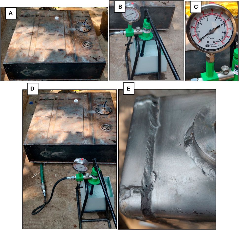
FIGURE 12. (A) Prototype Tank, (B) Apparatus to generate internal pressure, (C) Pressure gauge, (D) Testing of the tank, (E) Finished tank surface and welds.
The final measurements of the deformation of the tank are found at the highlighted location as marked in Figure 13 which are measured to compare the value from FEM results. The areas of maximum bulging are observed in the same locations as per the FEM results stated. The areas highlighted in Figure 10E are measured for deformation and values provided in Table 4 for three pressure values.
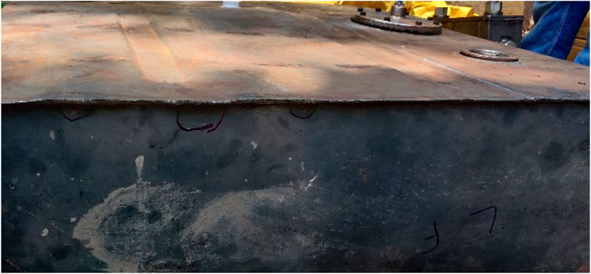
FIGURE 13. Deformed Tank under Pressure load.

TABLE 4. Experimentally measured values of deformation in tank.
The above Figure 14, shows the comparison of experimentally measured vs. FEM results for the Pressure values in bar of 0.1 (4.08%), 0.2 (0.12%), and 0.3 (2.91%) respectively for the three pressure values. As the error values are below 5%, we can assume the simulation to be accurate for future analysis, corresponding to real time analysis.
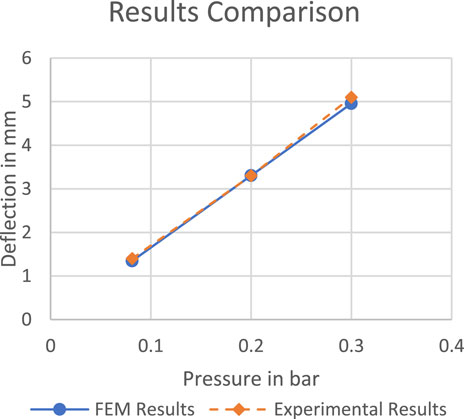
FIGURE 14. FEM vs. Experimental results comparison.
The paper is a comprehensive numerical and experimental analysis of the internal tank of 300L capacity for a heavy, off-road, tracked, ground vehicle. The tank has been initially analyzed for actual loading conditions which will resemble the working pressure of the tank in ideal conditions. Also, the tank has undergone dynamic loading conditions at 0.3 bar as per AIS 093. Both the tank and welds were analyzed under desperate conditions. The CFD analysis of external excitation of the tank under acceleration was analyzed for sloshing in the tank to predict fuel starvation and forces on the tank walls. The three numerical and experimental analyses have been able to conclude on the following points.
1. The maximum internal pressure analysis highlighted the areas of maximum stresses in the order of 160 MPa–200 MPa under actual working pressure of the tank, with a maximum deformation of 1.59 mm in the areas that are weakly supported.
2. For dynamic loading conditions, the tank shows a maximum stress of 431.4 MPa which is due to the bonded contact region between the baffles and side wall of corrugations of the tank, with a maximum deformation of 5.8 mm.
3. The sloshing analysis justified the design of baffles used, the net turbulent kinetic energy inside the liquid media was minimized. The peak forces on the tank walls were reduced from 150 N to 100 N. Although the baffle adds weight to the tank, it aids in the performance of the tank.
4. The welded joints highlighted a much clearer picture as there are more components to distribute stresses keeping the overall average values at lower region. Under actual loading conditions, the welds have been stressed to a maximum of 173.64 MPa, and maximum deformation of tank walls of about 1.34 mm.
5. Under dynamic loading conditions, the welds reached a maximum stress of 639MPa, whereas the tank walls were stressed until a maximum value of 277 MPa. With maximum structural deformation of 4.96 mm at weakly supported areas of the tank. This adheres with the hydraulic test as per AIS 093.
6. By the use of the fatigue tool, the life of various components has also been predicted for a cyclic, zero-based load of 120% of the working pressure of the tank, which highlighted the maximum stressed welds will have a minimum life of 5.2286e+7 cycles which is fairly high for the system as compared to the requirement.
7. The material CR-2 D as per IS 513 is indicated as a suitable alternative for the construction of the steel tank, which was tested for three pressure values. The test results were compared with FEM results, indicating a general error in the range of less than 5% to comprehend the cohesive work.
The original contributions presented in the study are included in the article/Supplementary material, further inquiries can be directed to the corresponding authors.
AV: Methodology, Project administration, Writing–original draft, Writing–review and editing. RS: Formal Analysis, Funding acquisition, Project administration, Resources, Supervision, Writing–review and editing. AM: Data curation, Formal Analysis, Investigation, Methodology, Project administration, Software, Supervision, Validation, Visualization, Writing–original draft, Writing–review and editing. BV: Data curation, Investigation, Methodology, Resources, Software, Validation, Visualization, Writing–original draft, Writing–review and editing. CS: Conceptualization, Data curation, Formal Analysis, Funding acquisition, Investigation, Methodology, Project administration, Resources, Software, Supervision, Validation, Writing–original draft, Writing–review and editing. NS: Formal Analysis, Methodology, Project administration, Software, Visualization, Writing–review and editing. SS: Investigation, Methodology, Project administration, Resources, Supervision, Writing–review and editing. RC: Methodology, Project administration, Software, Writing–review and editing. EA: Funding acquisition, Software, Supervision, Writing–review and editing.
The author(s) declare that no financial support was received for the research, authorship, and/or publication of this article.
The authors declare that the research was conducted in the absence of any commercial or financial relationships that could be construed as a potential conflict of interest.
All claims expressed in this article are solely those of the authors and do not necessarily represent those of their affiliated organizations, or those of the publisher, the editors and the reviewers. Any product that may be evaluated in this article, or claim that may be made by its manufacturer, is not guaranteed or endorsed by the publisher.
Abbasi, E., and Salmani, M. (2008). Investigation and improvement of corrosion resistance in automotive fuel tank. Adv. Mater. Res. 41, 491–497. doi:10.4028/www.scientific.net/AMR.41-42.491
Annamalai, S., Periyakgounder, S., Selvaraj, A. B., and Paramasivam, K. (2021). Deformation and stress analysis of a fuel tank under static loading condition. Mater. Today Proc. 39, 378–387. doi:10.1016/j.matpr.2020.07.604
Banagar, A. R. (2015). Modeling, stress and welding strength analysis of pressure vessel. https://archive.org/details/vol-2-issue-1/Vol%202%20Issue%201%20201501001%20Published1.
Basak, S., Das, H., Pal, T. K., and Shome, M. (2016). Corrosion behavior of MIG brazed and MIG welded joints of automotive DP600-GI steel sheet. J. Mater. Eng. Perform. 25, 5238–5251. doi:10.1007/s11665-016-2356-1
Comini, G., and Del Giudice, S. (1985). A (k-ε) model of turbulent flow. Numer. Heat. Transf. 8 (2), 133–147. doi:10.1080/01495728508961846
Du, P. J. (2017). FEM analysis and gas pressure intensity test of FL-61 wind tunnel. Sci. Technol. Eng. 17 (8), 303–306.
Everyspec (2007). MIL-DTL-27422D, DETAIL SPECIFICATION FOR THE TANK, FUEL, CRASH-RESISTANT, BALLISTIC-TOLERANT, AIRCRAFT (30 JAN 2007). http://everyspec.com/MIL-SPECS/MIL-SPECS-MIL-DTL/MIL-DTL-27422D_20366/#:∼:text=27422B(1)%5D-,MIL%2DDTL%2D27422D%2C%20DETAIL%20SPECIFICATION%20FOR%20THE%20TANK%2C,in%20rotorcraft%20and%20tilt%20rotorcraft.
Everyspec (2008). MIL-DTL-5578D, DETAIL SPECIFICATION: TANKS, FUEL, AIRCRAFT, SELF-SEALING (8 AUG 2008). http://everyspec.com/MIL-SPECS/MIL-SPECS-MIL-DTL/MIL-DTL-5578D_13567/#:∼:text=%2DT%2D5578C%5D-,MIL%2DDTL%2D5578D%2C%20DETAIL%20SPECIFICATION%3A%20TANKS%2C%20FUEL,tanks%20for%20use%20on%20aircraft.
Frosina, E., Senatore, A., Andreozzi, A., Fortunato, F., and Giliberti, P. (2018). Experimental and numerical analyses of the sloshing in a fuel tank. Energies 11 (3), 682. doi:10.3390/en11030682
Gao, Y., Ge, Z., Zhai, W., Tan, S., and Zhang, F. (2018a). The finite element modelling and dynamic characteristics analysis about one kind of armoured vehicles’ fuel tanks. IOP Conf. Ser. Mater. Sci. Eng. 301 (1), 012092. doi:10.1088/1757-899X/301/1/012092
Gao, Y., Ge, Z., Zhai, W., Tan, S., and Zhang, F. (2018b). The finite element modelling and dynamic characteristics analysis about one kind of armoured vehicles’ fuel tanks. IOP Conf. Ser. Mater. Sci. Eng. 301 (1), 012092. doi:10.1088/1757-899X/301/1/012092
Heinemann, P., Isopescu, D., and Maxineasa, S. G. (2021). Case studies on finite element modeling of welded joints. Bull. Polytech. Inst. Iași. Constr. Archit. Sect. 67 (2), 79–94. doi:10.2478/bipca-2021-0017
Hemer, A., Milovic, L., Grbovic, A., Aleksic, B., and Aleksic, V. (2020). Numerical determination and experimental validation of the fracture toughness of welded joints. Eng. Fail. Anal. 107, 104220. doi:10.1016/j.engfailanal.2019.104220
Hirt, C. W., and Nichols, B. D. (1981). Volume of fluid (VOF) method for the dynamics of free boundaries. J. Comput. Phys. 39 (1), 201–225. doi:10.1016/0021-9991(81)90145-5
Indian Standard (1992). Stainless steel plate, sheet and strip [MTD16: alloy Steels and Forgings]. https://law.resource.org/pub/in/bis/S10/is.6911.1992.pdf.
Indian Standard (2008). Cold reduced low carbon steel sheets and strips [MTD 4: wrought Steel Products]. https://law.resource.org/pub/in/bis/S10/is.513.2008.pdf.
Indian Standard (2023a). Phosphate treatment of iron and steel for protection against corrosion. https://law.resource.org/pub/in/bis/S10/is.3618.1966.pdf.
Indian Standard (2023b). Recommendations for manual tungsten inert-gas arc welding of austenitic stainless steel. https://law.resource.org/pub/in/bis/S10/is.2811.1987.pdf.
Kim, G. J., Rhee, H., Jeon, W. H., Jeong, J., and Hwang, D. S. (2020). Lateral sloshing analysis by CFD and experiment for a spherical tank. Int. J. Aeronautical Space Sci. 21, 816–825. doi:10.1007/s42405-020-00295-2
Kumaran, R., Arun, S. G., and Adepu, R. (2023). Design and development of fuel tank for high mobility military vehicle (No. 2023-28-1342). https://www.sae.org/publications/technical-papers/content/2023-28-1342/.
Rout, C., Li, H., Dupont, V., and Wadud, Z. (2022). A comparative total cost of ownership analysis of heavy duty on-road and off-road vehicles powered by hydrogen, electricity, and diesel. Heliyon 8 (12), e12417. doi:10.1016/j.heliyon.2022.e12417
Schäppi, R., Rutz, D., Dähler, F., Muroyama, A., Haueter, P., Lilliestam, J., et al. (2022). Drop-in fuels from sunlight and air. Nature 601 (7891), 63–68. doi:10.1038/s41586-021-04174-y
Ţălu, M., and Ţălu, Ş. (2018). Optimal engineering design of a pressurized paralepipedic fuel tank. Ann. Fac. Eng. Hunedoara-International J. Eng. Hunedoara, Romania 16, 193–200.
Zawawi, M. H., Saleha, A., Salwa, A., Hassan, N. H., Zahari, N. M., Ramli, M. Z., et al. (2018). A review: fundamentals of computational fluid dynamics (CFD). AIP Conf. Proc. 2030 (1). doi:10.1063/1.5066893
Zhang, E., and He, R. (2020). Numerical analysis on the sloshing of free oil liquid surface based on fuel tanks of different shapes. Proc. Institution Mech. Eng. Part C J. Mech. Eng. Sci. 234 (18), 3584–3599. doi:10.1177/0954406220916483
Keywords: baffle design, FEM, fuel starvation, sloshing analysis, steel fuel tank, tank deformation, weldment analysis
Citation: Verma A, Shankar R, Malik Shaik A, Veera Siva Reddy B, Chandrasekhara Sastry C, Shaik N, Salunkhe S, Cep R and Abouel Nasr E (2024) Comprehensive design and analysis of a 300L steel fuel tank for heavy off-road vehicles: numerical and experimental insights. Front. Mech. Eng 10:1360590. doi: 10.3389/fmech.2024.1360590
Received: 23 December 2023; Accepted: 24 January 2024;
Published: 12 February 2024.
Edited by:
Kaushik Kumar, Birla Institute of Technology, IndiaReviewed by:
Ján Dižo, University of Žilina, SlovakiaCopyright © 2024 Verma, Shankar, Malik Shaik, Veera Siva Reddy, Chandrasekhara Sastry, Shaik, Salunkhe, Cep and Abouel Nasr. This is an open-access article distributed under the terms of the Creative Commons Attribution License (CC BY). The use, distribution or reproduction in other forums is permitted, provided the original author(s) and the copyright owner(s) are credited and that the original publication in this journal is cited, in accordance with accepted academic practice. No use, distribution or reproduction is permitted which does not comply with these terms.
*Correspondence: B. Veera Siva Reddy, c2l2YXJlZGR5LmJvYmJpbGlAZ21haWwuY29t; C. Chandrasekhara Sastry, Y2hhbmRyYXNla2hhckBpaWl0ay5hYy5pbg==; Sachin Salunkhe, c2FjaGluc2FsdW5raGVAZ2F6aS5lZHUudHI=
Disclaimer: All claims expressed in this article are solely those of the authors and do not necessarily represent those of their affiliated organizations, or those of the publisher, the editors and the reviewers. Any product that may be evaluated in this article or claim that may be made by its manufacturer is not guaranteed or endorsed by the publisher.
Research integrity at Frontiers
Learn more about the work of our research integrity team to safeguard the quality of each article we publish.