 Haoting Jiang
 Hongjie Wang
 Jinlong Jiang
94% of researchers rate our articles as excellent or good
Learn more about the work of our research integrity team to safeguard the quality of each article we publish.
Find out more
ORIGINAL RESEARCH article
Front. Mater. , 19 March 2024
Sec. Structural Materials
Volume 11 - 2024 | https://doi.org/10.3389/fmats.2024.1379386
This article is part of the Research Topic Recent Advances in Durability Improvement and Low-Carbon Strategy of Engineering Materials and Structures View all 17 articles
Conventional stud connectors were proved to be inconvenient for the later disassembly and replacement in ultra-high performance concrete (UHPC) bridge decks. In this study, the headless studs which is a type of studs with their heads removed were employed as a substitute for conventional stud connectors, aiming to enhance the detachability of the bridge decks on the premise of ensuring the anti-lift bearing capacity of the decks. Three push-out specimens containing the headless studs with a diameter of 13 mm were carried out to study the mechanical properties of headless studs. In addition, the finite element model was developed to reveal the failure mechanism of headless studs in UHPC. Results indicated that the load-slip curve of headless stud connector can be divided into elastic stage, plastic stage and failure stage. The failure mode of headless studs was the shear fracture at the root of stud shank. Headless stud connections under cyclic loading can produce greater plastic deformation. The ultimate shear capacity and shear stiffness of headless studs were lower than those of conventional studs. Additionally, the UHPC slabs configured with headless studs have a small quantity of separation at the steel-UHPC interface, so it is suggested to use headless studs and conventional studs together in UHPC slabs to ensure the necessary anti-lift bearing capacity. Finite element analysis indicated that in the elastic stage, the bearing capacity of the push-specimen was dominated by the material properties of the headless stud. After entering the plastic stage, the bearing capacity of the push-specimen was mainly controlled by the UHPC below the headless stud.
Orthotropic steel bridge decks (OSD) are preferred for steel box girders or steel truss bridge decks due to their lower self-weight, lower material consumption, higher strength, and more convenient installation compared with concrete bridge decks (Luo et al., 2019; Zhu et al., 2022; Li et al., 2024). However, conventional orthotropic steel bridge decks exhibit lower local stiffness. Under the influence of wheel loads, the presence of welded residual stresses and stress concentration effects in the welded joint zone makes the decks more susceptible to fatigue damage (He et al., 2023; Zhu et al., 2021; van den Berg et al., 2021). Therefore, Shao et al. (Shao et al., 2013) proposed a composite material system composed of OSD and ultra-high performance concrete (UHPC)layers to enhance local stiffness. Dieng et al. (Dieng et al., 2013) pointed out that reinforcing the interaction between OSD and UHPC layers can significantly reduce stresses in both components. Conventional stud connectors welded to the steel plate are considered a reliable means to ensure a strong bonded interaction between OSD and UHPC layers (Cao et al., 2017; Jiang et al., 2022). Thus, conventional stud connectors play a vital role for the UHPC layer to assist the OSD in bearing the wheel loads of vehicles.
In the past few years, several studies investigated the shear behavior of the studs embedded in UHPC slabs. Kim et al. (Kim et al., 2015) conducted 15 push-out tests and found that when the aspect ratio of stud was reduced from 4 to 3.1 and the cover thickness over the stud head was decreased from 50 mm to 25 mm, the shear strength of stud would not be affected. A lower aspect ratio (2.7) and cover thickness (15 mm) were employed in the experiments conducted by Cao et al. (Cao et al., 2017), and the shear strength of stud could still be fully developed. Wang et al. (Wang et al., 2018; Wang et al., 2019) conducted experimental research on the static performance of large studs with diameter of 30 mm embedded in UHPC, it was found that UHPC could match the large studs very effectively, although the aspect ratio was reduced to 2.3. For demountable headed studs in UHPC, the minimum allowable aspect ratio was 1.5 (Wang et al., 2017). On the other hand, it was relatively conservative to arrange the studs in UHPC slabs using the minimum stud spacing in the longitudinal and transversal directions specified by current design codes (Hu et al., 2020). Kruszewski et al. (Kruszewski et al., 2018) and McMullen et al. (McMullen Kevin and Zaghi Arash, 2020) investigated the shear performance of the studs welded on corroded steel plates and embedded in UHPC. They discovered that the studs could reach their full strength even with stud spacing smaller than typically employed in practice. According to observations by Luo et al. (Luo et al., 2016a), a densely arranged longitudinal spacing of 3.5d could ensure the shear capacity of studs exceeding 0.9 times the full shear strength, while no strength reduction was observed with a transverse spacing of 2.3d.
UHPC is believed to have relatively great anchoring strength for conventional studs, which could be attributed to its excellent mechanical properties (Fang et al., 2024; Ding et al., 2021; Tian et al., 2022; Zhou et al., 2022; Zhang et al., 2023; Zhou et al., 2023; Fang et al., 2024; Leng et al., 2024; Ye et al., 2024). Lai et al. (Lai et al., 2023) experimentally investigated the pullout behavior of single studs and stud groups embedded in UHPC. The results showed that the single studs or stud groups embedded in UHPC had higher pullout strength and ductility than those embedded in NC. Lu et al. (Lu et al., 2021) conducted experimental research on the tensile performance of cast-in-place headed bolts embedded in high-strength concrete (HSC) and UHPC thin members of various embedment depths. They found that the anchorage performance of bolts in thin UHPC members was better than that in HSC. Additionally, according to the study by Choi et al. (Choi et al., 2015), the bearing capacity and displacement capacity of the anchors in ultra-high-performance fiber-reinforced concrete under tension and shear were significantly better than those in normal concrete. Li et al. (Li et al., 2022) studied the pull-out behavior of studs in UHPC with steel fibers. The results indicated that the UHPC specimens with steel fibers exhibited greater initial stiffness and better ductility than those without fibers. These findings further substantiate the feasibility of conventional studs which embedded in UHPC slabs.
Although conventional stud connectors are a viable option in OSD-UHPC composite bridge decks, they still have shortcomings. The head of conventional stud are firmly anchored within the UHPC, making the removal of damaged UHPC bridge deck units extremely challenging. Therefore, the use of conventional studs in UHPC is not conducive to the maintenance, replacement, and reusability for composite structures (Luo et al., 2012; Jurkiewiez et al., 2021; Zou et al., 2023). The conventional studs have excess anchored strength because of the exceptional performance of UHPC, this study attempts to release the constraint of conventional stud by removing its head (hereinafter called “headless studs”), as shown in Figure 1. The purpose of this approach is to enhance the efficiency of later removal and replacement of UHPC bridge deck units on the premise of ensuring the anti-lift bearing capacity. At present, research on the performance of headless studs has not been covered. To study the mechanical properties of headless studs embedded in UHPC, three push-out tests under monotonic and cyclic loads were carried out. In addition, the failure mechanism of headless studs was analyzed based on finite element model.
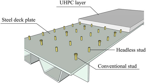
FIGURE 1. Headless studs in orthotropic steel-UHPC bridge deck.
The push-out specimens are favored by many researchers because of their advantages such as small specimen size and low stress redistribution in studs (Cao et al., 2017; Fang et al., 2023a). In this study, there push-out specimen was used to study the shear behavior of headless studs. The specimens were designed with reference to Eurocode-4 (Anderson, 2023). The steel beam was made of two T-shaped steels made of Q345. The material of headless studs was M15, the diameter was 13 mm, and the height was 27 mm. The 12 headless studs were welded on the steel flanges on both sides of the specimen in three rows and two columns. The thickness of UHPC slab was 50 mm and the headless studs have a cover thickness of 15 mm. The reinforced steel bars in the UHPC slab were made of HRB400 and had a diameter of 10 mm. The structures of each push-out specimen were exactly the same, as shown in Figure 2. Among these three specimens, two were monotonically loaded specimens and one was cyclically loaded. They were distinguished by M and C and named DS-M1, DS-M2 and DS-C respectively.
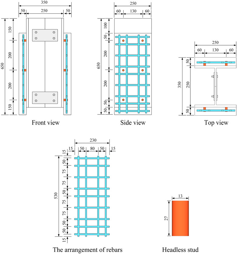
FIGURE 2. Dimensions of specimen (unit: mm).
The fabrication of push-out specimens was divided into 5 steps in total. (1) Welded the headless studs to the both sides of the steel flange according to the designated position. (2) Made formworks according to the size of the specimen and tied the steel bars. (3) Assembled the steel components and formworks. (4) Applied lubricating oil to the interface of steel plate and placed steel bars into formworks. (5) Poured UHPC. After the specimens were produced, they were watered and cured under natural conditions for 28 days. The fabrication steps of specimens are shown in Figure 3.
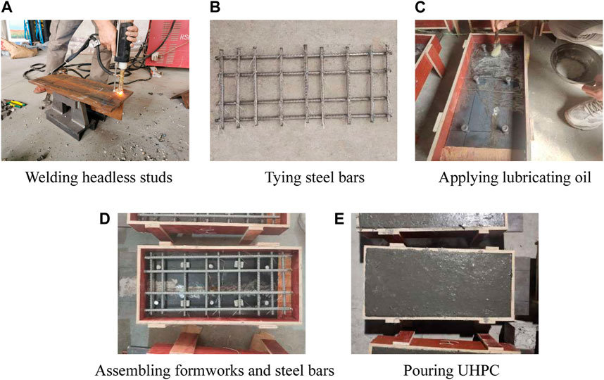
FIGURE 3. The manufacturing process of push-out specimens. (A) Welding headless studs. (B) Tying steel bars. (C) Applying lubricating oil. (D) Assembling formworks and steel bars. (E) Pouring UHPC.
In this study, the selected UHPC is formulated by mixing cement, silica fume, quartz sand, quartz flour, water reducing agent, water, and steel fibers. The dry material mix ratio of UHPC is listed in Table 1.
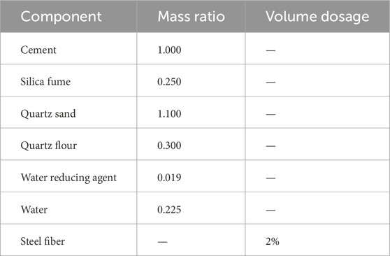
TABLE 1. Dry material mix ratio of UHPC.
According to GB/T31387-2015 (General Administration of Quality Supervision, 2015), the compressive strength of UHPC was determined by conducting axial compression tests on cubic specimens, while the tensile strength was measured through axial tension tests on dog-bone-shaped specimens. Following the Chinese standard (China NTMC, 2010), the mechanical properties of the steel plate (Q345) and steel bar (HRB400) were measured through tension tests using the electronic universal testing machine (CMT2503). As shown in Figure 4, on the premise of ensuring the welding quality, the steel bars with a diameter greater than the diameter of the head of stud (22 mm) were welded at each end of the studs, and then the tensile tests were performed on these components to obtain the mechanical properties of studs. The specific performance parameters of the above materials are shown in Table 2.
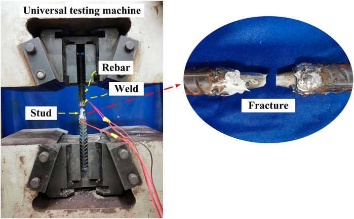
FIGURE 4. Mechanical property test of stud.
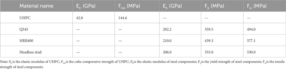
TABLE 2. Material properties of specimens.
As shown in Figure 5A, the push-out specimens were tested in an electrohydraulic servo pressure testing machine with a capacity of 1,000 t. In order to ensure uniform force distribution on the studs on both sides of the specimen during the test, a small quantity of fine sand was placed at the bottom of the specimen and subsequently leveled using a balance ruler. The loading devices were arranged on top of the steel plate in the following order: spreading plate, circular cushion block, pressure transducer, and another circular cushion block. Six linear variable displacement transducers (LVDT) were used, as shown in Figure 5B, to measure the relative slip and relative separation between UHPC and steel plate, thereby obtaining the load-slip curve and load-separation curve. S1 and S2 in the figure are the tangential slip measuring points in the middle, while T1, T2 and B1, B2 are the normal separation measuring points at the top and bottom respectively. The thrust load during the test can be directly read from the digital display instrument on the pressure testing machine.
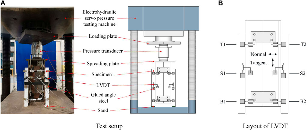
FIGURE 5. Test setup and layout of LVDTs. (A) Test setup. (B) Layout of LVDT.
As shown in Figure 6, the loading procedure consists of monotonic and cyclic loading. Three preloading were performed before formal loading, and the force was set to 30% of the predicted ultimate load (Pu), the Pu here was determined through numerical simulation before loading, and its value was 720 kN. Monotonic loading means loading from zero load to failure of the specimen. Cyclic loading involves cycling between 0 Pu to 0.5 Pu and 0 Pu to 0.7 Pu ten times each and then loading beyond 0.7 Pu until failure of the specimen. During the elastic stage, loading was conducted in increments of 10 kN with a loading rate not exceeding 1 kN/s. During the elastic-plastic stage, loading was conducted in increments of 5 kN with a loading rate not exceeding 0.5 kN/s. The displacement control was utilized when the specimen entered the plastic stage or slip was observed, and a loading of 0.05 mm per level was applied.
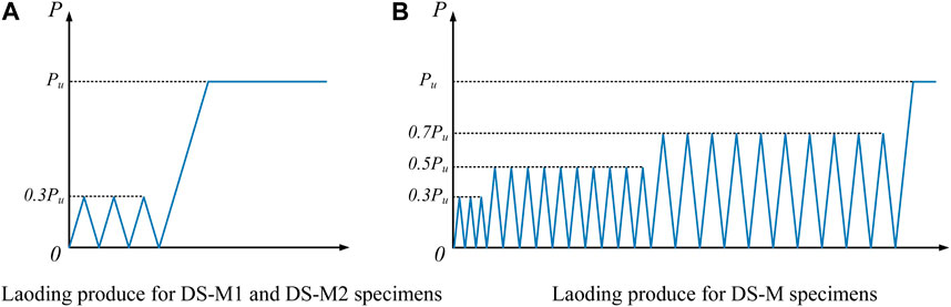
FIGURE 6. Loading produce for push-out tests. (A) Laoding produce for DS-M1 and DS-M2 specimens. (B) Laoding produce for DS-M specimens.
When each specimen was loaded to failure, the final shape of the specimen was recorded. As shown in Figure 7A, all three specimens showed that one side UHPC slab fell off from the steel beam. This is because it is difficult to ensure that the stress state of headless studs on both sides of specimen is exactly the same during the test, the headless studs on both sides did not fail at the same time. Among them, the left side slab of DS-M1 and DS-M2 specimens fell off, while the right slab of DS-C specimen fell off. Figure 7B shows the details of the interface between UHPC plate and steel flange. It can be seen from Figure 7B that the failure of the three specimens was controlled by the fracture of stud shank near the root of the headless stud. The headless studs were still embedded in the UHPC and there was no obvious pull-out phenomenon. The welds on the steel flanges remain intact. In addition, except for the partial crushing at the root of headless stud, there was no damage in other areas on the inside of the UHPC slab, and there were no obvious cracks or damage on the outside. These phenomena were basically similar to the failure modes of the push-out specimens of conventional studs in UHPC (Kim et al., 2015; Cao et al., 2017; Tong et al., 2020).
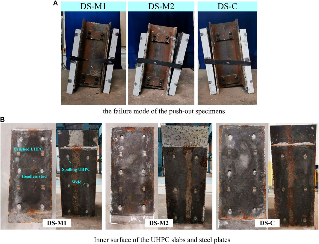
FIGURE 7. Failure modes of push-out specimens. (A) the failure mode of the push-out specimens. (B) Inner surface of the UHPC slabs and steel plates.
Figure 8 shows the load-slip curves of all specimens, where the load represents the shear strength per headless stud (Pstud), which is calculated by dividing the shear capacity of specimen (Pu) by headless stud numbers. The interface slip is represented as the average of two vertical LVDTs (i.e., (S1+S2)/2, Figure 5B. For the DS-M1 and DS-M2 specimens under monotonic loading, the load slip curve can be divided into three stages. (1) Elastic stage (A1∼B1): The load increases linearly with slip. (2) Plastic stage (B1∼C1): As the slip increases, the UHPC under the root of headless stud was gradually crushed, the headless stud begins to undergo plastic deformation, and the load growth slows down. (3) Descending stage (After C1): After the load exceeded the ultimate bearing capacity, the headless studs were sheared off one after another, and the load dropped rapidly.
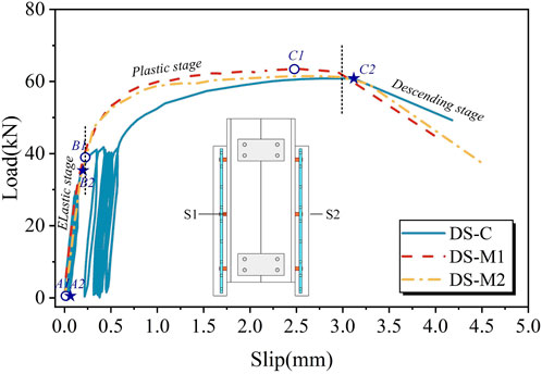
FIGURE 8. Load-slip curves.
The DS-C specimen under cyclic loading can also be divided into the above three stages. When the cyclic load was 0.5 Pu, the headless studs was basically in the elastic stage (A2∼B2), the residual deformation after cyclic loading was small, and the loading and unloading curves basically coincide. After the 10th unloading of 0.5 Pu was completed, the residual slip was 0.041 mm. When the cyclic load was 0.7Pu, the headless studs had begun to undergo plastic deformation. The residual deformation after cyclic loading gradually increases with the number of loadings. The loading and unloading curves do not overlap. After the 10th 0.7 Pu unloading was completed, the residual slip reached 0.450 mm. It can be observed that the residual slip of the specimen under 0.7 Pu cyclic load is more obvious, which could be attributed to the gradual increase in cumulative deformation with the increase in the number of loadings after the headless studs yielded. However, the slip of the DS-C specimen under ultimate load was 22.15% and 19.07% higher than that of the DS-M1 and DS-M2 specimens respectively, and the ultimate bearing capacity was only 4.21% and 1.10% lower. It shows that cyclic loading has little effect on the bearing capacity of the headless studs, but it helps to improve the plastic deformation ability of the headless studs.
According to Eurocode 4 (Anderson, 2023), when the load of the connector reached the characteristic value (i.e., the load drops to 0.9 Pu), the interface slip is not less than 6 mm before it can be called a “plastic connector”. As can be seen from Figure 8, the characteristic slip of three specimens was in the range of 3.41–3.65 mm. Therefore, the headless studs in UHPC do not meet the requirements of plastic connectors.
As shown in Figure 5B, the interfacial separation between steel plate and UHPC slab was measured using four transverse LVDTs. The top separation is represented as (T1+T2)/2, while the bottom separation is represented as (B1+B2)/2. Here, two specimens under monotonic loading were used for analysis, and the load-separation curves are shown in Figure 9. It can be seen that the trends of all load-separation curves are relatively similar to the trends of the load-slip curves. During the elastic phase, the bellow separation grew faster than the upper separation. After entering the plastic stage, the separation growth accelerated as the headless stud yielded. When the ultimate load was reached, the top separation and below separation of the DS-M1 specimen was 0.483 mm and 1.367 mm respectively, and top separation and below separation of the DS-M2 specimen was 0.814 mm and 0.935 mm respectively. Obviously, the below separation part was larger than the top separation, because the inevitable friction caused the transferred load to be applied eccentrically on the UHPC slab, thus causing the lateral deformation of the UHPC slab (Xu et al., 2012). Further, for the thin UHPC bridge deck with a thickness of 55 mm, a shear span length of 1,200 mm, and a conventional stud spacing of 200 mm, the interfacial separation between steel beam and UHPC slab was 1.17 mm under ultimate load (Xu, 2022). This result is 17% smaller than the maximum interfacial separation of the UHPC slab configured with headless studs in this study. Therefore, it is suggested to use headless studs together with conventional studs in UHPC slabs to ensure sufficient anti-lifting bearing capacity.
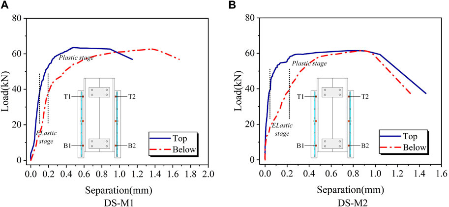
FIGURE 9. Load-separation curves. (A) DS-M1. (B) DS-M2.
Since there have been some studies on the shear performance of conventional studs in UHPC (Kim et al., 2015; Wang et al., 2018; Ding et al., 2021; Fang et al., 2023b), in this study, we plan to use existing research results to compare with the experimental results of this paper. To ensure that the data comparison is valuable, existing data need to be screened. The filtering principles include the following four conditions: (1) The conventional stud diameter is 13 mm; (2) The UHPC compressive strength is greater than 120 MPa; (3) The group stud effect is not considered; (4) Specimens under monotonic loading.
Figure 10 shows the comparison of the shear capacity of selected conventional studs with the test results in this paper. It can be seen from Figure 10 that the test results in this paper are close to the results of the research by Cao et al. (Cao et al., 2017), and lower than the research results of Li et al. (Li et al., 2021) and Wu et al. (Wu et al., 2022) This is because in the study by Cao et al. (Cao et al., 2017), stud fractures were mostly caused by weld fracture, and there was almost no local damage of the UHPC slab. But in other studies, it was basically the shear failure of the stud shank. On average, the shear capacity of headless studs is 16.3% lower than that of conventional studs. This may be because the headless stud loses the head restriction, and there may be a slight pull-out displacement in the normal direction, which leads to large plastic deformation at its root, an increase in stress level, and a decrease in bearing capacity.
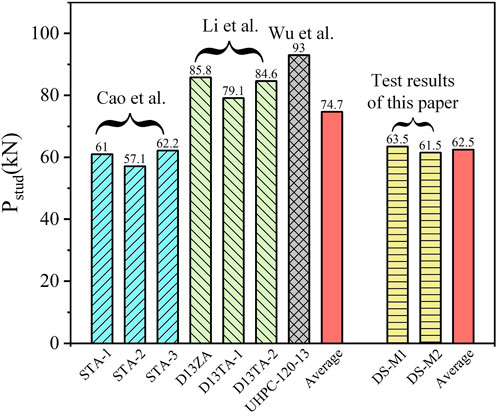
FIGURE 10. Comparison of shear strength (Cao et al., 2017; Li et al., 2021; Wu et al., 2022).
Shear stiffness is an important indicator to measure whether the composite structure has good composite effect. The shear stiffness can be calculated based on the load-slip curve, which is defined as the slope of a secant line on the load-slip curve. Some researchers also use the slope of the secant line where the slip is 0.2 mm to express the shear stiffness (Tong et al., 2020; Zou et al., 2022). Cao et al. (Cao et al., 2017) used 3 methods to calculate the shear stiffness of conventional studs in UHPC. The results showed that the higher the point on the secant line, the lower the shear stiffness. For a single stud, the shear stiffness of stud obtained by the three methods varies between 266 and 396 kN/mm. However, since the slip of the stud in UHPC is relatively small, considering that the slip will have a greater impact on the shear stiffness, this paper adopted the method recommended in JSSC (2002) (JSSC Japan Society of Civil Engineers, 2002) to calculate the shear stiffness. JSSC (2002) (JSSC Japan Society of Civil Engineers, 2002) prefers to use points corresponding to 1/3 Pu. The shear stiffness calculated using selected data and test results is listed in Table 3. It can be seen from Table 3 that the shear stiffness of the headless studs is lower than that of the conventional studs. The average shear stiffness of conventional studs (STA-1 to UHPC-120–13) is 354.8, and the average shear stiffness of headless studs is 224.3. The average shear stiffness of headless studs is 36.8% lower than that of conventional studs. This may be attributed to the deformation of the headless studs during the elastic phase is larger than that of the conventional studs, resulting in lower shear stiffness.

TABLE 3. Shear stiffness for conventional studs and headless studs (Cao et al., 2017; Li et al., 2021; Wu et al., 2022).
The FE analysis was performed in the ABAQUS Explicit Module. The nonlinear contact as well as material damage and failure behavior can be powerfully simulated using the explicit central difference rule (Simulia, 2014; Guan et al., 2022; Xu et al., 2022). The FE models consisted of five components: H-section steel, UHPC layer, headless stud, weld, and steel bar. Considering the symmetry of geometry and loading, only a quarter of the push-out specimen was modeled to enhance computational efficiency.
As shown in Figure 11A, the UHPC layer, H-section steel, headless studs, and welds were simulated utilizing the C3D8R element type provided by the ABAQUS element library. C3D8R can prevent unexpected element shear locking, making it a suitable method for nonlinear analysis with reasonable accuracy (Mia, 2017). The steel bars were constructed via B31 elements because they primarily acted as constraints on the concrete. It is worth noting that for studs embedded in UHPC, the welds should be modeled in the analysis considering their necessary contribution to the shear strength of studs (Cao et al., 2017; Cao and Shao, 2019; Tong et al., 2020; Huang et al., 2021). In this study, the modeling method for welds was referenced from the literature (Cao and Shao, 2019), where a 1 mm × 1 mm slope was simulated at the top corner of the weld, as shown in Figure 11B. To accurately simulate the severe distortion of the headless stud and the contact behavior between UHPC layer and steel plate, a refined mesh was essential in these specific zones. Thus, the size of the element representing the root of headless studs and the surrounding UHPC material was set to 2.5 mm, and other zones were set to 8 mm.
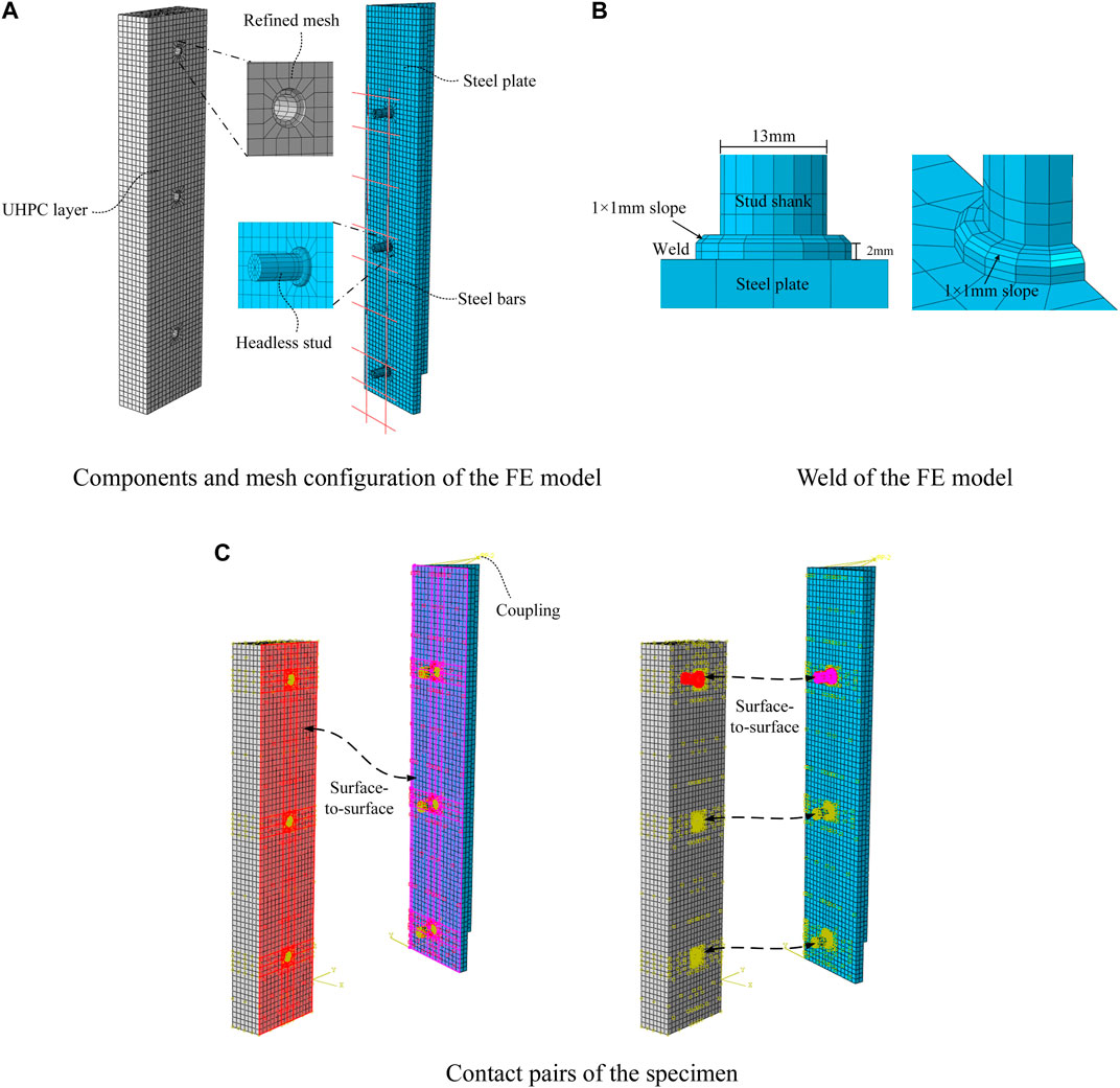
FIGURE 11. FE model of push-out specimen. (A) Components and mesh configuration of the FE model. (B) Weld of the FE model. (C) Contact pairs of the specimen.
As shown in Figure 11C, the involved contact pairs were the steel-UHPC interface and the headless stud-UHPC interface. A surface-to-surface contact was applied on the above-mentioned contact pairs. In this contact model, the normal behavior between the two surfaces was defined as “hard contact” in the normal direction. For headless stud-UHPC interface, a “penalty function method” was utilized for the tangential direction, with a friction coefficient of 0.4 (Luo et al., 2016b; Huang et al., 2021; Guan et al., 2022). While the friction coefficient was not defined for the steel-UHPC interface.
Based on the symmetry of the specimens, the symmetric boundary conditions were applied to the surface along the symmetric plane of the model. While all degree of freedoms were restricted at the bottom of UHPC layer. Steel bars were embedded into the UHPC layer through the “embedded region constraints” available in ABAQUS. In addition, the top surface of the steel beam was coupled to a point, a 6 mm displacement was applied to this point, and a smoothing analysis step was set to prevent load fluctuations.
The steel plate and steel bars were assumed to be ideal elastic-plastic materials. Their constitutive relationship was based on the tri-line stress-strain curve as shown in Figure 12A (Zou et al., 2021), and the mechanical properties are shown in Table 2.
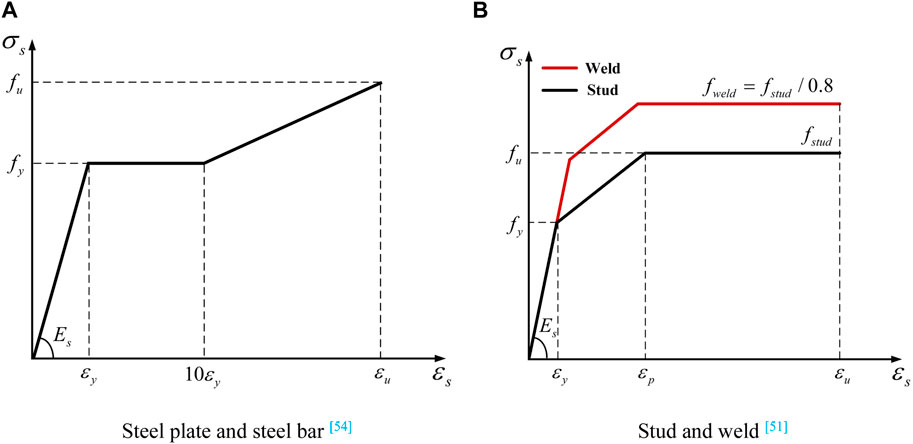
FIGURE 12. Material constitutive relations of steel (Cao and Shao, 2019; Zou et al., 2021). (A) Steel plate and steel bar Zou et al., 2021. (B) Stud and weld Cao and Shao, 2019.
Figure 12B illustrates the stress-strain curves of headless studs and welds. The main parameters of the headless stud constitutive obtained from the tensile test were as follows: fy = 355 MPa, fu = 530 MPa, εy = 0.003, εp = 0.04, εu = 0.12. It has been previously verified by Cao et al. (Cao and Shao, 2019) that the predicted load-slip curve generally agreed well with the test results when the weld strength (fweld) was no less than that of the studs (i.e., fweld = fstud/0.8). Consequently, the stress-strain relationship of the welds in FE model was defined as fweld = fstud/0.8.
The CDP model in ABAQUS can simulate the damage and failure process of the UHPC layer (Lubliner et al., 1989; Lee and Fenves, 1998). For UHPC, its stress-strain curves for tension and compression behaviors need to be defined independently. Cao et al. (Cao and Shao, 2019) adopted the UHPC constitutive model that exhibited good agreement with the experimental results, including the stress-strain relationship in tension (Eq. 1) and the stress-strain relationship in compression (Eq. 2). Two types of stress-strain curves for UHPC are shown in Figure 13. The plasticity parameters of UHPC material are shown in Table 4.
where, fc is the compressive strength of UHPC, and its value is 144.6 MPa. ft is the tensile strength of UHPC, and its value is 8.9 MPa. ξ is compressive strain ratio, defined as ξ = ε/εcp. εcp is the compressive strain corresponding to compressive strength, whose value is 0.0038. n is the elastic modulus ratio, defined as n = Ec/Et. Ec is the initial elastic modulus, and its value is 42.0 GPa. Et is the secant modulus at the compressive strength in the compressive stress-strain curve.
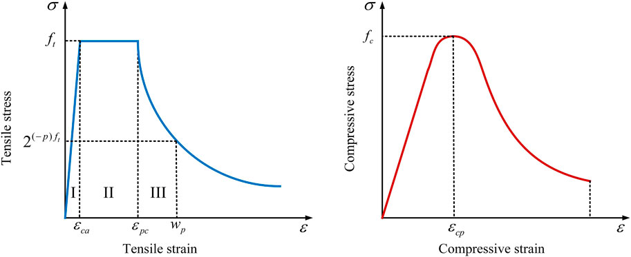
FIGURE 13. Stress-strain curves of UHPC (Cao and Shao, 2019).

TABLE 4. Plasticity parameters of UHPC material.
Figure 14 shows the comparison between the FE analysis results based on the load-slip curve and the test results. It can be seen from Figure 14 that the curve trend obtained by FE calculation was close to the test results. The ultimate bearing capacity per headless stud in the FE was 62.6 kN, and the ratios to the DS-M1 and DS-M2 specimens were 0.99 and 1.02 respectively. The slip corresponding to the ultimate bearing capacity of the FE model was 2.419 mm, and the slip corresponding to the ultimate bearing capacity of the DS-M1 and DS-M2 specimens was 2.553 mm and 2.619 mm respectively, i.e., the errors were 5.2% and 3.0% respectively. These results show that the load-slip curve calculated by FE model is in good agreement with the test results.
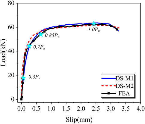
FIGURE 14. Comparison of load-slip curves from tests and FE analysis.
Figure 15 shows the comparison of the failure mode between test results and FE analysis results. The compressive and tensile damage coefficients of concrete (DAMAGC and DAMAGT), along with the equivalent plastic strain (PEEQ) were used to track the UHPC and headless stud failure zones, respectively. As can be seen from Figure 15A, the damage of UHPC in the FE results appeared in a very small zone around the headless studs. The compressive damage mainly occurred at the rear of headless studs, while the tensile damage was obvious at the front of headless studs. Figure 15B shows the PEEQ of the steel components in FE results. The zones in gray represent that the PEEQ exceeds 20%, and at this threshold, the stud fracture is assumed (Xu et al., 2022). It can be observed that the gray zones appeared at the junction of stud shank and weld, indicating that the failure of headless studs is caused by the fracture at the root of stud shank. The results observed above are in good agreement with the test results.
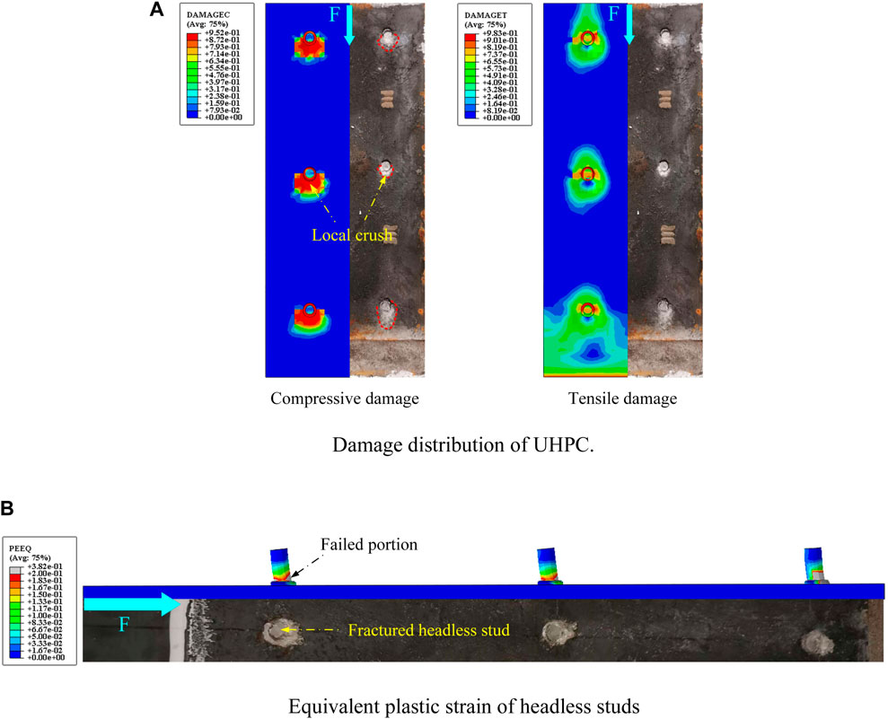
FIGURE 15. Comparison of experimental results and FE results. (A) Damage distribution of UHPC. (B) Equivalent plastic strain of headless studs.
Based on the stress slicing function in ABAQUS, the failure process of the headless stud in UHPC was observed, as shown in Figure 16. Here, q represents the resistance produced by UHPC to prevent headless stud from bending, and the red arrow corresponds to the maximum stress of headless stud and UHPC. The number of steps shown corresponds to the star markings in Figure 14. When the load was 0.3Pu, the headless stud was in the elastic stage. The bearing capacity mainly comes from the material properties of headless stud, and the bearing capacity increases rapidly. When the bearing capacity reached 0.7Pu, the headless stud begins to yield gradually, and the stress of the UHPC below the root of headless stud increased. At this time, the bearing capacity was mainly provided by UHPC, and the growth of bearing capacity was slower than before. In addition, a small amount of gap was observed at the rear end of the weld, which was caused by the downward movement of the steel beam. When the load was 0.85Pu, the stress of the local UHPC below headless stud exceeded the ultimate compressive stress, indicating that it was crushed. The plastic deformation of the headless stud becomes larger and larger. This moment the bearing capacity continued to be provided by UHPC. However, there was a slight pull-out displacement on the top of the headless stud, and a small separation occurred at the interface between the steel beam and UHPC. When the load reached 1.0Pu, the stress at the intersection between the root of headless stud and the weld was close to 530 MPa. The stress of the UHPC near headless stud continued to increase, and the bearing capacity was still mainly provided by UHPC. When the load exceeded 1.0Pu, the headless stud was sheared along its root, and the bearing capacity decreases rapidly.
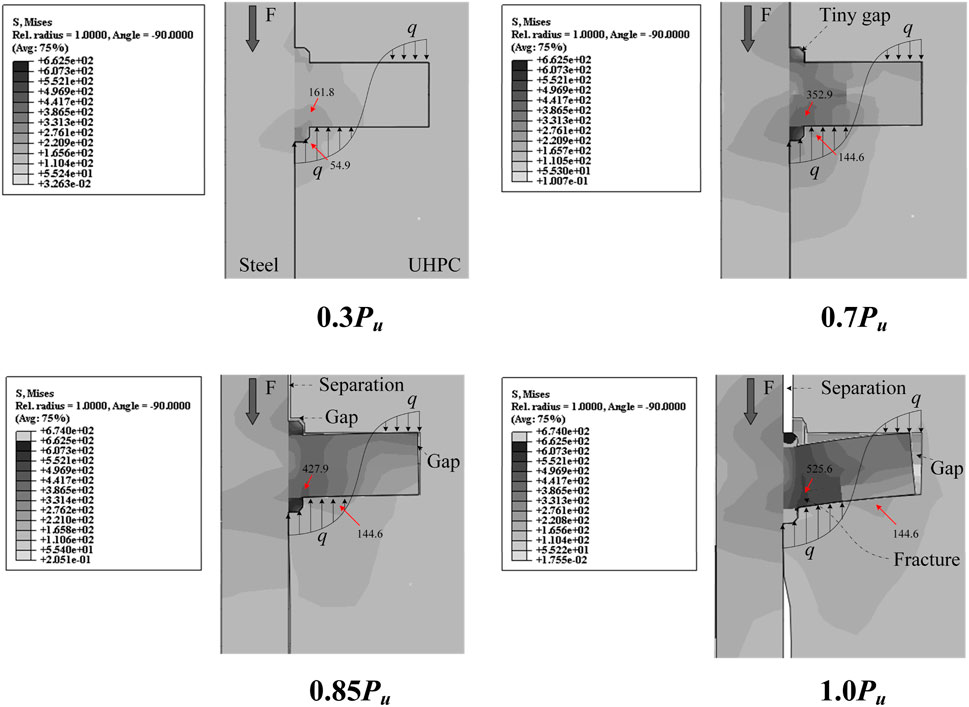
FIGURE 16. Failure process.
The following conclusions can be drawn from this research:
■ A push-out test was conducted on the headless stud embedded in UHPC, and it was found that the load-slip curve of the headless stud can be divided into three stages, namely, elastic stage, plastic stage and failure stage.
■ The failure of the pushed-out specimen was dominated by the fracture of the root headless stud. There were signs of local crushing for the UHPC below the root of headless stud, but other than that, there was no obvious damage in other area.
■ Under cyclic loading, the headless stud connector has greater plastic deformation capability. Compared with the specimens under monotonic loading (DS-M1, DS-M2), the slip of the specimen under cyclic loading (DS-M) at the ultimate bearing capacity increased by 22.15% and 19.07%, but the ultimate bearing capacity only decreased by 4.21% and 1.10%.
■ Under the ultimate load, the maximum separation at the steel-UHPC interface of the UHPC slab configured with headless studs is 17% larger than that of the UHPC slab configured with conventional studs. Consequently, it is suggested to use headless studs together with conventional studs in UHPC slabs to ensure sufficient anti-lifting bearing capacity.
■ Headless studs embedded in UHPC have lower load-bearing capacity and stiffness than conventional studs. Compared with conventional studs from which previous studies were collected, the average bearing capacity of per headless stud in this paper decreased by 16.3%, and the average shear stiffness decreased by 36.8%.
■ The FE model well simulated the mechanical behavior of the headless stud in UHPC. The analysis results show that when the headless stud had not yielded, the bearing capacity of the push-out specimen mainly came from the material properties of the headless stud itself. After the headless stud produced plastic deformation, the bearing capacity of the push-out specimen was mainly provided by the UHPC below headless stud.
The original contributions presented in the study are included in the article/Supplementary material, further inquiries can be directed to the corresponding author.
HJ: Conceptualization, Methodology, Writing–review and editing. HW: Formal Analysis, Software, Writing–original draft. XD: Data curation, Investigation, Writing–original draft. YL: Project administration, Resources, Validation, Writing–original draft. HZ: Data curation, Funding acquisition, Resources, Writing–original draf. CW: Data curation, Supervision, Writing–original draft. JJ: Resources, Supervision, Writing–review and editing.
The author(s) declare that financial support was received for the research, authorship, and/or publication of this article. The authors express their sincere gratitude for the financial support provided by the National Natural Science Foundation of China (Grant No. 52278147, 52208302, 52278293), the Science and Technology Research Program of Chongqing Municipal Education Commission (KJZD-M202300706), the Natural Science Foundation of Chongqing, China (CSTB2023NSCQ-MSX0019), the Major Science and Technology Projects in Hainan (ZDKJ2021048).
The authors declare that the research was conducted in the absence of any commercial or financial relationships that could be construed as a potential conflict of interest.
All claims expressed in this article are solely those of the authors and do not necessarily represent those of their affiliated organizations, or those of the publisher, the editors and the reviewers. Any product that may be evaluated in this article, or claim that may be made by its manufacturer, is not guaranteed or endorsed by the publisher.
Anderson, D. (2023). Eurocode 4 - design of composite steel and concrete structures. Berlin, Germany: Springer.
Cao, J., and Shao, X. (2019). Finite element analysis of headed studs embedded in thin UHPC. J. Constr. Steel Res. 161, 355–368. doi:10.1016/j.jcsr.2019.03.016
Cao, J., Shao, X., Deng, L., and Gan, Y. (2017). Static and fatigue behavior of short-headed studs embedded in a thin ultrahigh-performance concrete layer. J. Bridge Eng. 22. doi:10.1061/(asce)be.1943-5592.0001031
China NTMC (2010). National technical management committee of China. “Standard for metallic materials-tensile testing-Part 1: method of test at room temperature”. (GB/ T228-2010). Beijing: China NTMC.
Choi, S., Joh, C., and Chun, S.-C. (2015). Behavior and strengths of single cast-in anchors in Ultra-High-Performance Fiber-Reinforced Concrete (UHPFRC) subjected to a monotonic tension or shear. KSCE J. Civ. Eng. 19, 964–973. doi:10.1007/s12205-013-0246-8
Dieng, L., Marchand, P., Gomes, F., Tessier, C., and Toutlemonde, F. (2013). Use of UHPFRC overlay to reduce stresses in orthotropic steel decks. J. Constr. Steel Res. 89, 30–41. doi:10.1016/j.jcsr.2013.06.006
Ding, J., Zhu, J., Kang, J., and Wang, X. (2021). Experimental study on grouped stud shear connectors in precast steel- UHPC composite bridge. Eng. Struct., 242. doi:10.1016/j.engstruct.2021.112479
Fang, S., Zhang, S., Cao, Z., Zhao, G., Fang, Z., Ma, Y., et al. (2023b). Effects of stud aspect ratio and cover thickness on push-out performance of thin full-depth precast UHPC slabs with grouped short studs: experimental evaluation and design considerations. J. Build. Eng., 67. doi:10.1016/j.jobe.2023.105910
Fang, Z., Hu, L., Jiang, H., Fang, S., Zhao, G., and Ma, Y. (2023a). Shear performance of high-strength friction-grip bolted shear connector in prefabricated steel–UHPC composite beams: finite element modelling and parametric study. Case Stud. Constr. Mater. 18, e01860. doi:10.1016/j.cscm.2023.e01860
Fang, Z., Wu, J., Xu, X., Ma, Y., Fang, S., Zhao, G., et al. (2024). Grouped rubber-sleeved studs–UHPC pocket connections in prefabricated steel–UHPC composite beams: Shear performance under monotonic and cyclic loadings. Eng Struct. 305, 117781. doi:10.1016/j.engstruct.2024.117781
Fang, Z., Wu, J., Zhao, G., Fang, S., Ma, Y., and Jiang, H. (2024). Shear performance and design recommendations of single embedded nut bolted shear connectors in prefabricated steel–UHPC composite beams. Steel Compos. Struct. 50 (3), 319–336. doi:10.12989/scs.2024.50.3.319
General Administration of Quality Supervision (2015). Inspection and Quarantine, beijing, China. Reactive powder concrete. (GB/T 31387-2015). Beijing, China: General Administration of Quality Supervision. (in Chinese).
Guan, Y., Wu, J., Sun, R., Ge, Z., Bi, Y., and Zhu, D. (2022). Shear behavior of short headed studs in Steel-ECC composite structure. Eng. Struct., 250. doi:10.1016/j.engstruct.2021.113423
He, X., Wu, C., Wang, R., Wei, L., and Jiang, C. (2023). Experimental study on buckling behavior of orthotropic steel deck with slender open ribs for large span suspension bridges. J. Constr. Steel Res. 201, 107681. doi:10.1016/j.jcsr.2022.107681
Hu, Y., Meloni, M., Cheng, Z., Wang, J., and Xiu, H. (2020). Flexural performance of steel-UHPC composite beams with shear pockets. Structures 27, 570–582. doi:10.1016/j.istruc.2020.05.039
Huang, Y., Chen, S., and Gu, P. (2021). Static and fatigue behavior of shear stud connection embedded in UHPC. Structures 34, 2777–2788. doi:10.1016/j.istruc.2021.09.043
Jiang, L., Nie, L., Zhou, W., Wu, X., and Liu, L. (2022). Distortional buckling analysis of steel-concrete composite box beams considering effect of stud rotational restraint under hogging moment. J. Central South Univ. 29, 3158–3170. doi:10.1007/s11771-022-5130-6
JSSC (Japan Society of Civil Engineers) (2002). Guidelines for performance-based design of steel-concrete hybrid structures. Tokyo: JSSC.
Jurkiewiez, B., Tout, F., and Ferrier, E. (2021). Push-out and bending tests of steel-concrete adhesively bonded composite elements. Eng. Struct., 231. doi:10.1016/j.engstruct.2020.111717
Kim, J.-S., Kwark, J., Joh, C., Yoo, S.-W., and Lee, K.-C. (2015). Headed stud shear connector for thin ultrahigh-performance concrete bridge deck. J. Constr. Steel Res. 108, 23–30. doi:10.1016/j.jcsr.2015.02.001
Kruszewski, D., Wille, K., and Zaghi, A. E. (2018). Push-out behavior of headed shear studs welded on thin plates and embedded in UHPC. Eng. Struct. 173, 429–441. doi:10.1016/j.engstruct.2018.07.013
Lai, Z., Han, Y., Huang, J., and Yang, X. (2023). Pull-out behavior and design of headed studs in steel-UHPC composite structures. Compos. Struct., 319. doi:10.1016/j.compstruct.2023.117135
Lee, J., and Fenves, G. L. (1998). Plastic-damage model for cyclic loading of concrete structures. J. Eng. Mech. 124, 892–900. doi:10.1061/(asce)0733-9399(1998)124:8(892)
Leng, J., Yang, J., Zhang, Z., Du, J., Zou, Y., and Zhou, J. (2024). Effect of vehicle-induced vibration on the strength, nano-mechanical properties, and microstructural characteristics of ultra-high-performance concrete during hardening process. Cem. Concr. Compos. 148, 105487. doi:10.1016/j.cemconcomp.2024.105487
Li, F., Tang, H., Wen, T., Li, J., Chen, Z., Jiang, Y., et al. (2022). Pullout behavior of studs in ultra-high performance concrete with steel fibers and novel structural fibers. Structures 44, 405–417. doi:10.1016/j.istruc.2022.08.017
Li, M., Shao, X., Cao, J., He, G., and Chen, Y. (2021). Performance of experimental and theoretical analysis on shear short headed studs embedded in UHPC. China J. Highw. Transp. 34, 191–204. (in Chinese). doi:10.19721/j.cnki.1001-7372.2021.08.016
Li, X., Lin, H., Zhao, A., Wang, R., Feng, Z., Zhang, S., et al. (2024). Experimental study on fatigue performance of double welded orthotropic steel bridge deck. J. Constr. Steel Res. 213, 108418. doi:10.1016/j.jcsr.2023.108418
Lu, K., Xu, Q., Wang, M., Yao, Y., and Wang, J. (2021). Anchorage performance of bolt connection embedded in thin UHPC members. Structures 34, 1253–1260. doi:10.1016/j.istruc.2021.08.060
Lubliner, J., Oliver, J., Oller, S., and O?Ate E, (1989). A plastic-damage model for concrete. Int. J. Solids Struct. 25, 299–326. doi:10.1016/0020-7683(89)90050-4
Luo, P., Zhang, Q., Bao, Y., and Bu, Y. (2019). Fatigue performance of welded joint between thickened-edge U-rib and deck in orthotropic steel deck. Eng. Struct. 181, 699–710. doi:10.1016/j.engstruct.2018.10.030
Luo, Y., Hoki, K., Hayashi, K., and Nakashima, M. (2016a). Behavior and strength of headed stud–SFRCC shear connection. I: experimental study. J. Struct. Eng. 142, 142. doi:10.1061/(asce)st.1943-541x.0001363
Luo, Y., Hoki, K., Hayashi, K., and Nakashima, M. (2016b). Behavior and strength of headed stud–SFRCC shear connection. II: strength evaluation. J. Struct. Eng. 142, 142. doi:10.1061/(asce)st.1943-541x.0001372
Luo, Y., Li, A., and Kang, Z. (2012). Parametric study of bonded steel–concrete composite beams by using finite element analysis. Eng. Struct. 34, 40–51. doi:10.1016/j.engstruct.2011.08.036
McMullen Kevin, F., and Zaghi Arash, E. (2020). Experimental evaluation of full-scale corroded Steel Plate girders repaired with UHPC. J. Bridge Eng. 25, 04020011. doi:10.1061/(asce)be.1943-5592.0001535
Mia, M. (2017). Investigation of load-slip behavior and fatigue life of headed shear stud connector. https://core.ac.uk/download/pdf/211519869.pdf.
Shao, X., Yi, D., Huang, Z., Zhao, H., Chen, B., and Liu, M. (2013). Basic performance of the composite deck system composed of orthotropic steel deck and ultrathin RPC layer. J. Bridge Eng. 18, 417–428. doi:10.1061/(asce)be.1943-5592.0000348
Simulia, D. S. (2014). ABAQUS analysis user’s manual, version 6.14. Rhode Island, USA: Dassault Systemes Simulia, Inc.
Tian, C., Wang, Y., Qiu, K., and Yang, Q. (2022). Effects of submicron-MgO and nano-MgO on the expansion and microscopic properties of high-performance concrete. J. Central South Univ. 29, 3186–3200. doi:10.1007/s11771-022-5090-x
Tong, L., Chen, L., Wen, M., and Xu, C. (2020). Static behavior of stud shear connectors in high-strength-steel–UHPC composite beams. Eng. Struct., 218. doi:10.1016/j.engstruct.2020.110827
van den Berg, N., Xin, H., and Veljkovic, M. (2021). Effects of residual stresses on fatigue crack propagation of an orthotropic steel bridge deck. Mater. Des., 198. doi:10.1016/j.matdes.2020.109294
Wang, J., Qi, J., Tong, T., Xu, Q., and Xiu, H. (2019). Static behavior of large stud shear connectors in steel-UHPC composite structures. Eng. Struct. 178, 534–542. doi:10.1016/j.engstruct.2018.07.058
Wang, J., Xu, Q., Yao, Y., Qi, J., and Xiu, H. (2018). Static behavior of grouped large headed stud-UHPC shear connectors in composite structures. Compos. Struct. 206, 202–214. doi:10.1016/j.compstruct.2018.08.038
Wang, J.-Y., Guo, J.-Y., Jia, L.-J., Chen, S.-M., and Dong, Y. (2017). Push-out tests of demountable headed stud shear connectors in steel-UHPC composite structures. Compos. Struct. 170, 69–79. doi:10.1016/j.compstruct.2017.03.004
Wu, F., Feng, Y., Dai, J., and Wang, G. (2022). Study on mechanical properties of stud shear connectors in steel-uhpc composite structures. Eng. Mech. 39 (2), 222–234. (in Chinese). doi:10.6052/j.issn.1000-4750.2021.05.0389
Xu, C., Sugiura, K., Wu, C., and Su, Q. (2012). Parametrical static analysis on group studs with typical push-out tests. J. Constr. Steel Res. 72, 84–96. doi:10.1016/j.jcsr.2011.10.029
Xu, Q. (2022). Experimental study and refined analysis on new interfacial connections for steel-uhpc composite beam bridge 2022. (in Chinese).
Xu, Q., Sebastian, W., Lu, K., Yao, Y., and Wang, J. (2022). Shear behaviour and calculation model for stud-UHPC connections: finite element and theoretical analyses. Eng. Struct. 254, 113838. doi:10.1016/j.engstruct.2022.113838
Ye, M., Li, L., Pei, B., Yoo, D.-Y., Li, H., and Zhou, C. (2024). A critical review on shear performance of joints in precast Ultra-High-Performance Concrete (UHPC) segmental bridges. Eng. Struct. 301, 117224. doi:10.1016/j.engstruct.2023.117224
Zhang, Z., Pang, K., Xu, L., Zou, Y., Yang, J., and Wang, C. (2023). The bond properties between UHPC and stone under different interface treatment methods. Constr. Build. Mater. 365, 130092. doi:10.1016/j.conbuildmat.2022.130092
Zhou, C., Wang, J., Jia, W., and Fang, Z. (2022). Torsional behavior of ultra-high performance concrete (UHPC) rectangular beams without steel reinforcement: experimental investigation and theoretical analysis. Compos. Struct. 299, 116022. doi:10.1016/j.compstruct.2022.116022
Zhou, C., Wang, J., Shao, X., Li, L., Sun, J., and Wang, X. (2023). The feasibility of using ultra-high performance concrete (UHPC) to strengthen RC beams in torsion. J. Mater. Res. Technol. 24, 9961–9983. doi:10.1016/j.jmrt.2023.05.185
Zhu, A., Ouyang, S., Chen, Y., and Sun, Y. (2022). Fatigue test and life evaluation of rib-to-deck connections in orthotropic steel bridge decks. J. Constr. Steel Res. 197, 107442. doi:10.1016/j.jcsr.2022.107442
Zhu, Z., Li, J., Huang, Y., and Carpinteri, A. (2021). Hot-spot stress models of cutout detail on orthotropic steel bridge decks. J. Constr. Steel Res. 183, 106762. doi:10.1016/j.jcsr.2021.106762
Zou, Y., Guo, J., Zhou, Z., Wang, X., Yu, Y., and Zheng, K. (2022). Evaluation of shear behavior of PCSC shear connection for the construction of composite bridges with prefabricated decks. Eng. Struct., 257. doi:10.1016/j.engstruct.2022.113870
Zou, Y., Jiang, J., Yang, J., Zhang, Z., and Guo, J. (2023). Enhancing the toughness of bonding interface in steel-UHPC composite structure through fiber bridging. Cem. Concr. Compos. 137, 104947. doi:10.1016/j.cemconcomp.2023.104947
Keywords: steel-UHPC composite structure, shear connector, demountable, headless stud, shear performance
Citation: Jiang H, Wang H, Deng X, Li Y, Zhou H, Wu C and Jiang J (2024) Shear performance of headless studs in ultra-high performance concrete bridge deck. Front. Mater. 11:1379386. doi: 10.3389/fmats.2024.1379386
Received: 31 January 2024; Accepted: 05 March 2024;
Published: 19 March 2024.
Edited by:
Zhidong Zhang, ETH Zürich, SwitzerlandReviewed by:
Cong Zhou, Hunan University of Science and Technology, ChinaCopyright © 2024 Jiang, Wang, Deng, Li, Zhou, Wu and Jiang. This is an open-access article distributed under the terms of the Creative Commons Attribution License (CC BY). The use, distribution or reproduction in other forums is permitted, provided the original author(s) and the copyright owner(s) are credited and that the original publication in this journal is cited, in accordance with accepted academic practice. No use, distribution or reproduction is permitted which does not comply with these terms.
*Correspondence: Jinlong Jiang, amlubG9uZ2ppYW5nQG1haWxzLmNxanR1LmVkdS5jbg==
Disclaimer: All claims expressed in this article are solely those of the authors and do not necessarily represent those of their affiliated organizations, or those of the publisher, the editors and the reviewers. Any product that may be evaluated in this article or claim that may be made by its manufacturer is not guaranteed or endorsed by the publisher.
Research integrity at Frontiers
Learn more about the work of our research integrity team to safeguard the quality of each article we publish.