 Qiao Yan1,2
 Shifu Qin
 Zuosen Luo
95% of researchers rate our articles as excellent or good
Learn more about the work of our research integrity team to safeguard the quality of each article we publish.
Find out more
ORIGINAL RESEARCH article
Front. Mater. , 31 March 2023
Sec. Structural Materials
Volume 10 - 2023 | https://doi.org/10.3389/fmats.2023.1177733
This article is part of the Research Topic Physico-Mechanical Properties and Treatment Technology of Hazardous Geomaterials, volume II View all 17 articles
The hard Flint limestone of Shuibuya hydropower station underground construction cavern is utilized as a research object to investigate the creep problem caused by excavation of rock masses such as caverns. In order to perform a triaxial compression grade-unloading creep test, the actual adjustment path of stress during excavation of underground cavern surrounding rock is used. Limestone under different confistiff pressures is then evaluated. Based on the Nishihara model, the elastic damage element considering time-dependent damage is introduced, and the unloading creep constitutive model of stiff Flint limestone is established and verified by experiments. The results show: 1) Deformation and creep strain appear at all stress levels. 2) As the unloading amount increased from 2 to 4 MPa, the quasi-destructive stresses of the samples were smaller from 83 to 79 MPa, indicating that the unloading amount affected the final creep damage strength of the rock samples. In other words, the higher the unloading amount, the lower the ultimate creep failure strength. 3) When entering the accelerated creep stage, the axial and lateral creep strains of the sample increase non-linearly, and the rupture duration of the sample is very short. Therefore, the creep deformation and creep rate characteristics of this stage should be paid attention to in practical engineering. 4) Different from the loading stress path, the failure mode of the Flint limestone rock sample is different. When the unloading amount is 2 and 4 MPa, the creep failure mode of the Flint limestone rock sample is shear failure, showing a significant oblique section crack. 5) The non-linear creep model curve of aging damage and the fitting effect of the unloading creep test curve are acceptable. The rationality of the established non-linear creep model is illustrated.
According to many engineering practices, surrounding rock at the early stage of construction will not show damage or instability immediately, but with the passage of time, rock mass engineering develops the long-term load creep phenomenon, resulting in rock mass engineering damage (Li, 1999; Sun, 1999; Peng et al., 2020). Therefore, it is necessary to study the creep characteristics of actual engineering rock mass to ensure the safety and stability of its long-term operation.
The rock creep mechanics test is the main method for studying the creep characteristics of rock under long-term loads. Because soft rock has significant creep characteristics, the creep characteristics of soft rock have been studied in the past (Fan et al., 2010; Li and Yang, 2018; Liu et al., 2020). At the same time, creep tests under more loading stress paths were carried out, and more rock creep results were obtained (Park et al., 2017; Li et al., 2019). Despite this, few studies have been conducted on creep under unloading stress. The excavation of rock mass for engineering structures such as caverns causes the stress of surrounding rocks to be redistributed. This results in some rock being in an unloading stress state. For practical engineering purposes, it is necessary to study the creep properties of rock under unloading paths. Underground caverns, tunnels and tunnels are often excavated in layers, and the size of the excavation unload affects the stability of the rockwork. Therefore, it is necessary to study the effect of unloading amount on rock creep under the unloading stress path (Li, 2000; Li et al., 2007).
According to Zhu (2009), the green sandstone in the diversion tunnel of Jinping II hydropower station was used as a research object. Indoor rheological tests were conducted under constant axial pressure and gradual unloading of confining pressure to determine the rotational and lateral deformation characteristics. Huang et al. (2016) carried out triaxial unloading creep tests of sandy mudstone under continuous axial pressure and step-by-step unloading confining pressure, and studied the horizontal, lateral and volumetric creep laws of soft rock and the characteristics of the deviatoric stress-strain relationship during the unloading process. A grading unloading rheological test was conducted under axial pressure unloading confining pressure and constant axial pressure unloading confining pressure by Deng et al. (2016). Sun et al. (2021) and Wang et al. (2018) proposed an improved Nishihara model reflecting non-linear creep characteristics. They analyzed the results of sandstone creep tests to describe accelerated creep behavior. Sun et al. (2015) established a non-constant Nishihara model by considering the relationship between creep flexibility and stress level and time, and non-constant Nishihara coefficients of the traditional Nishihara model were non-constant.
The influence of different unloading amounts on rock creep characteristics was less considered in the past unloading creep test because the research object was less stiff. To ensure the safety of reservoir dams in water-conservancy projects, hard-rock foundations with a rough texture are often chosen for the dam foundation. It is generally believed that hard rock is not prone to creep. But, under high stress conditions, hard rock with a dense texture will also show the creep deformation phenomenon (Wang et al., 2016; Wu et al., 2016). Under long-term loads, the creep of these hard rocks has brought significant potential safety hazards to the safe operation of hydropower stations (Li et al., 2009). It is necessary to carry out creep test research on such dense rocks to explore the creep characteristics and creep deformation mechanism of rocks.
In view of this, this paper uses the RLW-2000 triaxial creep test system to take the soft Flint limestone from the underground construction cavern of Shuibuya hydropower station as the test object, and carries out the triaxial unloading confining pressure creep test reflecting the time-dependent deformation characteristics of limestone after excavation. The creep deformation and failure law of rock under different unloading conditions is obtained. The unloading creep characteristics of surrounding rock are revealed, and the unloading creep deformation constitutive model is established.
Shuibuya hydropower station is located in Badong County, Hubei Province, China, the project began construction in 2000, completed in 2008, the project’s main buildings are dams, underground plants, emptying holes and spillways, etc., (Yang, 2010). The underground powerhouse and underground cavern of Shuibuya hydropower station are located on the right bank of the dam site, and the lithology in the stratum is complex. The stratum contains not only soft rock strata but also hard rock strata (Zhang et al., 2003).
Despite the underground cavern of Shuibuya hydropower station being stable at the beginning of its construction, monitoring data of the underground cavern of Shuibuya hydropower station shows that the top of the local cavern has deformed, fallen, and cracked (Chen et al., 2010; Jin, 2013). It not only damages the lines and equipment in the cavern of the hydropower station, but also seriously compromises its safety and stability. According to Dong et al. (2019), rock creep is the principal factor affecting the deformation of underground cavern chambers caused by rock excavation, unloading and stability monitoring. According to the theoretical analysis of this research result, it is known that rock creep is the main cause of the deformation of the underground cavern in Shuibuya hydropower station. However, experiments are needed to verify.
In order to clarify the root cause of underground cavern failure, it is necessary to carry out relevant rock tests for the phenomenon of local cavern failure. Due to severe deformation and failure on the top of the partially underground caverns of Shuibuya hydropower station and the strata below, which is Permian Qixia Formation, the rock of this formation is primarily composed of Flint limestone. Therefore, in order to ensure the safe operation of the hydropower station and take preventive measures, it is urgent to study the creep characteristics of Flint limestone and explore its failure mode, so as to evaluate the stability of underground caverns and put forward reasonable countermeasures, so as to provide scientific decision-making reference for the safe operation of underground caverns. Which is not only of great significance to the stability of Shuibuya hydropower station underground caverns, but also of significant significance to ensure the safe operation of Shuibuya hydropower station.
The relevant design, construction, and monitoring data of the Shuibuya hydropower station underground construction cavern group are collected, and the existing engineering investigation reports and research reports are examined and analyzed. According to the area with obvious deformation and failure signs on site, the representative tunnel section is selected as the key research area. The rock sample collection site is shown in Figure 1. Samples were taken on site to obtain complete rock samples. After drilling, cutting and grinding, a cylindrical standard sample with a diameter of 50 mm and a height of 100 mm was obtained. Acoustic wave detection is used to eliminate the discrete nature of rock samples by eliminating samples with abnormal wave velocity. In addition, rock samples with similar wave velocity are selected. Some test rock samples are shown in Figure 2.
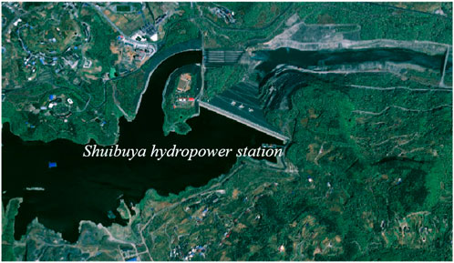
FIGURE 1. Rock sampling site.
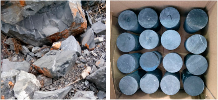
FIGURE 2. Complete rock and prepared standard rock specimens.
When undertaking underground cavern engineering, foundation engineering is not only in the state of axial loading, but is also in the state of lateral unloading. In order to study the creep characteristics of underground cavern rock under unloading stress state, this paper designs the creep test of Flint limestone under unloading condition. The experimental scheme for creep properties of Flint limestone is shown in Table 1. This experiment simulates the unloading of underground cavern excavations with constant and reduced loads.
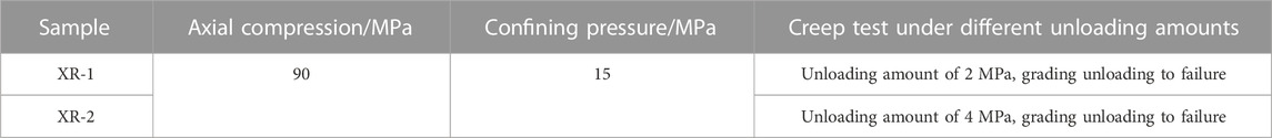
TABLE 1. Loading and unloading creep test scheme of Flint limestone.
The procedure for testing the creep properties of Flint limestone graded unloading is as follows: under the stress path of constant axial pressure and unloading confining pressure, the initial confining pressure is set to 15 MPa, and the axial pressure is loaded to 90 MPa (the triaxial compressive strength under the same circumferential pressure is 127.61 Mpa, and the axial pressure is about 70% of its value), and the confining pressure is unloaded with different unloading amounts, each stage is unloaded foru 24 h.
In the grading and unloading stress path, the axial pressure is constant, while the confining force is constant until failure, as shown in the stress path diagram Figure 3.
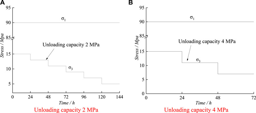
FIGURE 3. Stress path diagram of stepped unloading. (A) Unloduading capacity 2 MPa (B) Unloading capacity 4 MPa.
The test instrument used in the creep characteristic test is the RLW-2000 triaxial creep test system, as shown in Figure 4. The three-axis pressure chamber of this test system adopts a self-balancing pressure chamber, so that the pressure on the rock in all directions is the same when the rock is not under axial pressure, and in addition, there is no additional force on the axial pressure when the axial pressure is added, so the axial and radial deformation can be measured directly, which is especially suitable for long time creep test. The maximum load of this equipment is 2000 kn, measuring range 2%–100%, axial pressure measuring range 0–100 Mpa, measuring accuracy ±2%, displacement measuring range 0–50 mm, measuring accuracy ±0.5%, continuous working time more than 1,000 h.
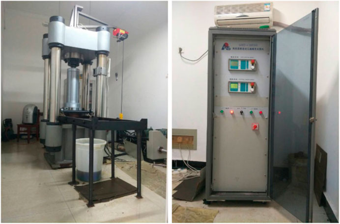
FIGURE 4. RLW-2000 Microcomputer controlled triaxial creep testing machine.
Under the graded unloading creep stress path, the initial confining pressure is 15 MPa. The graded unloading creep test with an unloading amount of 2 and 4 MPa is carried out. Each stage is unloaded for 24 h. Test results with unloading amounts of 2 and 4 MPa are used to analyze the creep deformation law of Flint limestone under unloading stress conditions. The creep curve of Flint limestone is shown in Figure 5.
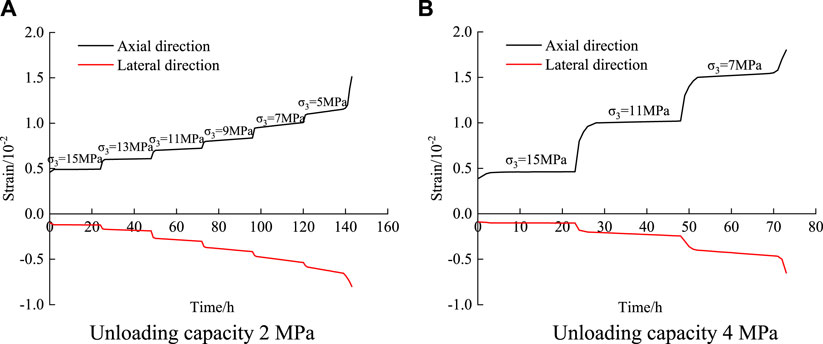
FIGURE 5. Triaxial unloading creep test curves of Flint limestone under different unloading amounts. (A) Unloading capacity 2 MPa (B) Unloading capacity 4 MPa.
The value above the creep curve in the figure indicates the size of the confining pressure at this stage. The longitudinal strain is positive in compressive strain and negative in tensile strain.
The specimen under constant confining pressure has experienced both decay creep and steady creep at all levels as shown in Figure 5. It transits from steady creep to non-linear accelerated creep until the specimen is destroyed at the rupture confining pressure level. This is consistent with the curve characteristics of creep under step loading.
The creep characteristic curve obtained by the graded unloading creep test is not convenient for the analysis of the creep characteristics of rock masses. It is necessary to process the results of the test. Chen’s loading treatment method (Liu, 1994) is a rock creep curve processing method proposed by Professor Chen Zongji. Compared with other creep curve processing methods, Chen’s loading treatment method has the advantages of being applicable to both linear creep and non-linear creep. Therefore, this paper uses Chen’s unloading treatment method to process the data of the graded unloading creep test. It transforms the whole curve into creep curves under various loads, as shown in Figure 6.
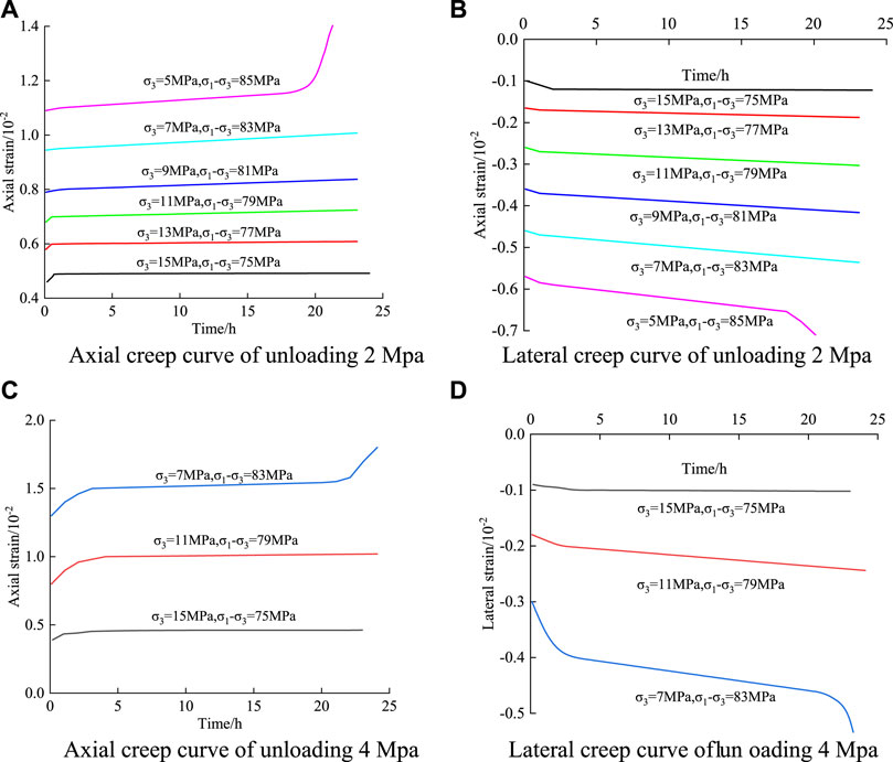
FIGURE 6. Triaxial unloading creep curve clusters of Flint limestone under different unloading amounts. (A) Axial creep curve of unloading 2 Mpa (B) Lateral creep curve of unloading 2 Mpa. (C) Axial creep curve of unloading 4 Mpa (D) Lateral creep curve of unloading 4 Mpa.
Data statistics of instantaneous deformation and creep deformation of Flint limestone specimens under unloading amounts of 2 and 4 MPa were collected. These data were used to investigate the characteristics of creep deformation of Flint limestone under unloading paths. The unloading creep characteristics of Flint limestone under different unloading amounts are shown in Table 2.
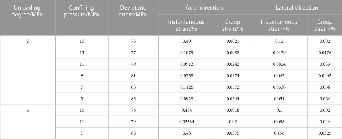
TABLE 2. Unloading creep characteristic indexes of Flint limestone under different unloading amounts.
From Figures 5, 6 and Table 2, the unloading creep deformation characteristics of Flint limestone are as follows:
1) Instability and strain appear at all levels of stress. The total strain of the sample increases with the gradual unloading of confining pressure. Under the condition of constant confining pressure at all levels, the lateral creep deformation of the sample is more significant than its axial creep deformation. This indicates that the lateral deformation of the sample is more significant than the vertical deformation, and the lateral expansion effect is obvious. This is different from the deformation law of creep under step loading. According to the test curve shown in Figure 5A, for the test curve with an initial confining pressure of 15 MPa, the axial creep strain and lateral creep strain under the first-stage steady state are 0.21 × 10⁻⁴ and 0.2 × 10⁻⁴, respectively. When unloading to 13 MPa, the axial creep strain and lateral creep strain are 0.88 × 10⁻⁴ and 1.76 × 10⁻⁴, respectively, which are 3.19 and 7.8 respectively compared with the previous level. The other levels also show the same law. Based on the above analysis, it can be seen that with the gradual reduction of pressure, lateral deformation develops rapidly. Additionally, lateral deformation is more sensitive to unloading. The reason is that during the test, with the gradual unloading of confining pressure, when the confining pressure is unloaded to the lowest level of confining pressure, the horizontal constraint on the sample is small, while the bias is large, and the sample is prone to lateral expansion failure.
2) Comparing the steady-state creep curves of samples under different unloading levels, the slope of the linear steady-state creep curve of the sample is close to 0 under the first and second confining pressure levels (15 MPa, 13 MPa) under the confining pressure unloading amount of 2 MPa, and the first confining pressure level (15 MPa) under the confining pressure unloading amount of 4 MPa. With the gradual unloading of confining pressure, when the confining pressure is unloaded to 11 MPa under the two test conditions, the steady-state creep curve of the sample develops from a nearly horizontal trend to a certain inclination angle. At this time, the axial steady-state creep rates are 0.01 × 10⁻³ h−1 and 0.0083 × 10⁻³ h−1, both of which are greater than 0. The reason is that the stress level gradually increases and exceeds the crack initiation strength of the sample, which leads to a certain plastic deformation of the sample. After the axial stress reaches a high level, a large number of cracks are generated within the rock sample, which expand rapidly, and the creep rate increases. The sample enters the accelerated creep stage after the steady-state creep stage, and the sample deforms rapidly until a macroscopic failure surface forms to reach the failure state. The creep failure of the specimen occurs at the last stress level, indicating that creep failure will occur when the deviatoric stress exceeds the reciprocal second-order stress level. Therefore, the reciprocal second-order stress level is determined as the quasi-failure stress of the rock specimen, and the quasi-failure stress
3) The total duration of creep failure of samples under confining pressure unloading of 2 and 4 MPa is different, which is 143.1 and 73.7 h respectively, and the start-up time of accelerated creep under different conditions is significantly different. It can be seen from Figure 5A that under the rupture stress level of confining pressure of 5 MPa and deviatoric stress of 83 MPa, the whole creep process lasted 23.7 h, the decay creep stage lasted 4.3 h, accounting for about 18.1% of the total time, the steady creep stage lasted 17.2 h, accounting for about 72.6% of the total time, and the non-linear rapid creep stage lasted 2.2 h, accounting for about 9.3% of the total time. Similarly, the creep time under the fracture stress level in Figure 5B is analyzed, and it is found that the change rule is basically the same as the above. The attenuation creep stage and non-linear accelerated creep stage lasted relatively short, while the steady creep stage lasted relatively long, but the deformation was small. When entering the accelerated creep stage, the axial and lateral creep strains of the sample increase non-linearly, and the rupture duration of the sample is very short. Therefore, the creep deformation and creep rate characteristics of this stage should be paid attention to in practical engineering.
In consideration of the time effect, the creep test data of rock are sorted. In this paper, the long-term strength index of Flint limestone is obtained by the isochronous curve method. On the basis of determining the long-term strength of Flint limestone, the relationship between long-term strength and instantaneous failure strength of Flint limestone is explored.
With the step unloading stress path, as shown in Figure 7, the isochronous curve method is used to obtain the isochronous curve clusters of Flint limestone under different unloading amounts. These amounts are under the unloading limits of 2 and 4 MPa.
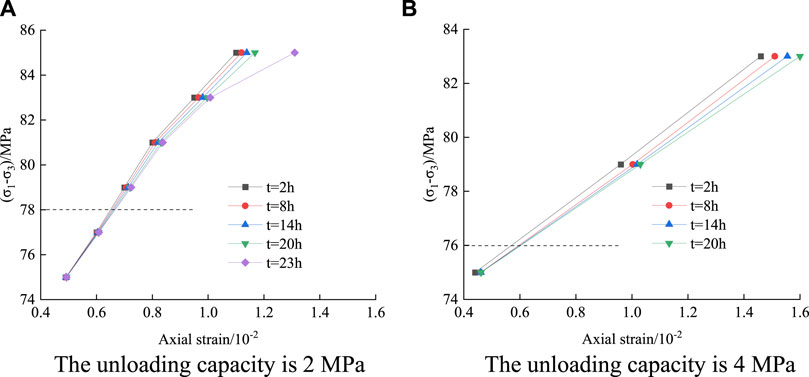
FIGURE 7. Creep isochronous curve clusters under different unloading amounts. (A) The unloading capacity is 2 MPa (B) The unloading capacity is 4 MPa.
Isochronous curves initially have a parabolic shape, then move towards a horizontal direction as shown in Figure 7. It can be seen from Table 3 that compared with the instantaneous strength of Flint limestone, the long-term strength of Flint limestone under long-term load is significantly lower than its creep failure strength.

TABLE 3. Long-term strength of Flint limestone under unloading stress path.
Under different stress paths, the creep failure forms for limestone are distinct. In order to further study the creep failure characteristics of Flint limestone, this paper lists photos of creep failure forms of Flint limestone under different stress states. Under the constant unloading stress path of axial compression, when the unloading amount is 2 and 4 MPa, the failure form of Flint limestone is shown in Figure 8.
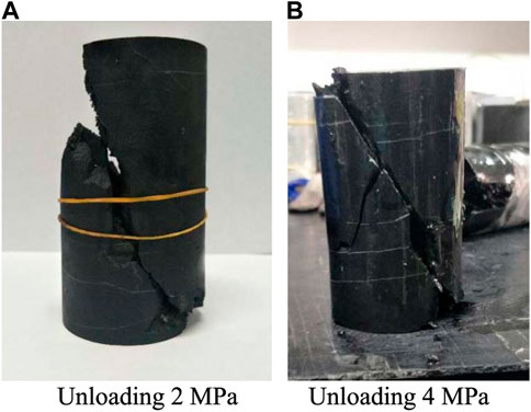
FIGURE 8. The creep failure modes of graded unloading under different unloading amounts. (A) Unloading 2 MPa (B) Unloading 4 MPa.
Based on Figure 8, it can be seen that the Flint limestone rock sample shows a different failure mode than the loading stress path. When the unloading amount is 2 and 4 MPa, the creep failure mode of the Flint limestone rock sample is shear failure. This is because the crack shows a significant oblique section crack, and the crack penetrates the upper and lower surfaces of the rock sample. When the unloading amount is 4 MPa, multiple cracks appear in the Flint limestone rock sample, and the crushing characteristics are severe, indicating a significant expansion phenomenon.
A study of the unloading creep curve characteristics of Flint limestone found that the instantaneous strain, attenuation creep, and uniform creep stages could be well described by the Nishihara model, while the non-linear accelerated creep stage could not be adequately explained by its viscoplastic element. Bai et al. (2021), Bai et al. (2023) obtained the generalized effective stress principle by varying the internal variable parameters to achieve a model that automatically takes into account the effects of stress paths, and the established model can accurately capture the loading path effects. Therefore, it is necessary to modify the Nishihara model to describe the curve of the non-linear accelerated creep stage of Flint limestone.
The traditional Nishihara model is shown in Figure 9, which is composed of elastomer, viscoelastic body and viscoplastic body. In the diagram,
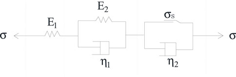
FIGURE 9. Nishihara model.
(1) When σ < σs, only part I and II in the model are involved in the rheology. Nishihara’s model degenerates into the generalized Kelvin model, which can describe attenuation creep, and the rock is in a stable state.
The corresponding creep constitutive model is obtained as follows:
(2) When σ ≥ σs, the I, II and III parts of the model are all involved in the response. At this time, the model can fully reflect the viscoelastic-plastic rheological properties of the rock. According to the combination relationship of the components, the constitutive equation of the model is derived as follows:
The corresponding creep constitutive model is further derived as follows:
Therefore, the creep equation of the Nishihara model is:
Any real number γ, Riemann-Liouville fractional order function can be expressed as
Where γ is the derivative order, ξ is the variable, f (t) is a function of t, and Γ(γ) is the Gamma function.
The fractional-order Abel viscous pot does not take into account the damage degradation of the material, and the intrinsic model is only applicable to the case where the external load is less than the yield stress, i.e., when creep does not enter the accelerated phase. The intrinsic relationship (Liu, 2019) for the Abel viscous pot is
where ηγ is the viscosity coefficient.
Keeping the stress σ constant and applying the Riemann-Liouville type fractional order calculus theory to solve Eq. 7, we can obtain the Abel viscous pot instanton equation.
During the non-linear accelerated creep phase, the creep parameters of the rock are time-dependent, requiring the introduction of damage variables to describe the degradation of the viscosity coefficient ηγ of the Abel viscous pot.
where D is the damage variable, 0 ≤ D ≤ 1.
The damage variable is assumed to accumulate as a negative exponential function over time (Wu et al., 2020).
Where α is the time effect coefficient.
Substituting Eqs 9, 10 into Eq. 7 yields the intrinsic structure relationship for Abel’s viscous pot.
Keeping the stress σ constant, applying the Riemann-Liouville type fractional order calculus theory to solve Eq. 11, we get
Based on the Nishihara model, the viscous element of the viscoplastic body is replaced by the variable coefficient Abel viscous pot. A non-linear creep damage model considering age damage is established as shown in Figure 10.
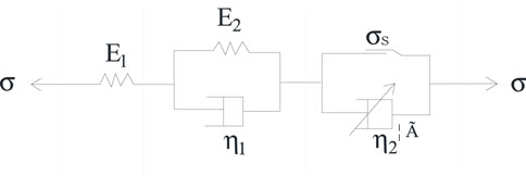
FIGURE 10. Non-linear creep damage model considering time-dependent damage.
In the one-dimensional stress state, the total strain ε is,
where the stress-strain relationship for the elastic Hooke body, viscoelastic body is,
For viscoplastic strains in viscoplastic bodies, there are 2 cases depending on the magnitude of the stress σ and the long-term strength σs.
(1) When σ < σs, the friction slider does not start and the viscoplastic strain is 0, i.e., εvp = 0.
(2) When σ ≥ σs, the friction slider is activated and the intrinsic relationship of the viscoplastic body can be determined.
where
The non-constant fractional order viscoplastic strain can be obtained by Laplace transform and Laplace inverse transform as,
Considering the strain of model 3 individuals together, the intrinsic equation of the non-linear creep damage model can be expressed as,
The results of the identification of the parameters of the non-linear creep model considering aging damage are shown in Table 4.
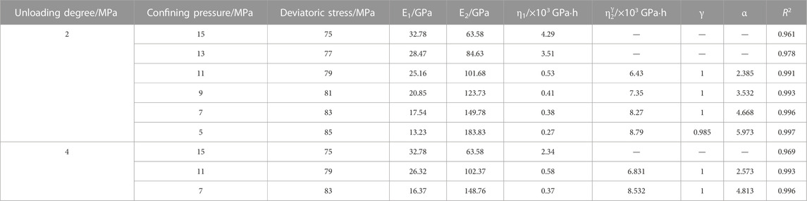
TABLE 4. Parameter identification of a non-linear creep model with aging damage.
As can be seen in Table 4, the fitted R2 values are all larger than 0.961. This is because the non-linear Nishihara creep model considering the damage variables can better reflect the creep characteristics of Flint limestone. The relationship between the creep parameters and the ambient pressure is complicated, but the general rule is: when the unloading amount is certain, the smaller the surrounding pressure is, the smaller the instantaneous elastic modulus E1 and viscosity coefficient η have a tendency to decrease, and the trend is more obvious when the unloading amount increases. It shows that the decrease in the surrounding pressure will not only reduce the instantaneous elastic modulus of the rock, but also intensify the plastic flow characteristics of the rock and enhance the viscous flow characteristics.
In order to verify the proposed non-linear creep damage model considering aging damage, the curves simulated by the non-linear creep model incorporating decay damage and the data curves from the indoor tests were fitted for comparison, and the results are shown in Figure 11, which show that the two fits are better and illustrate the reasonableness of the revised non-linear creep model considering aging damage.
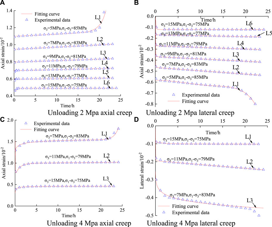
FIGURE 11. Creep curve and model curve fitting results. (A) Unloading 2 Mpa axial creep (B) Unloading 2 Mpa lateral creep. (C) Unloading 4 Mpa axial creep (D) Unloading 4 Mpa lateral creep.
(1) The specimens have been subjected to decay creep and steady creep stages under all levels of constant confining pressure, and have transitioned from steady creep to non-linear accelerated creep until failure under rupture confining pressure.
(2) With the increase of the unloading amount, the quasi-failure stress of the sample gradually increases, indicating that the unloading amount affects the final creep failure strength of the rock sample, that is, the greater the unloading amount, the lower the final creep failure strength.
(3) In the accelerated creep stage, the axial and lateral creep strains of the specimen increase non-linearly, and the rupture duration of the specimen is very short. Therefore, the creep deformation and creep rate characteristics of this stage should be paid attention to in practical engineering.
(4) When the unloading amount is 2 and 4 MPa, the creep failure mode of the Flint limestone rock sample is shear failure, showing a significant oblique section crack. When the unloading amount is 2 and 4 MPa, the creep failure mode of the Flint limestone rock sample is different from the failure mode caused by the loading stress path.
(5) Based on damage mechanics theory, a non-linear creep damage model considering time-dependent damage is established. Unloading creep models are identified based on creep test results. It provides a theoretical basis for geotechnical engineering design when the creep model curve and the test curve agree well.
The original contributions presented in the study are included in the article/supplementary material, further inquiries can be directed to the corresponding author.
All authors listed have made a substantial, direct, and intellectual contribution to the work and approved it for publication.
This work was supported by Key Laboratory of Geological Hazards on Three Gorges Reservoir Area (China Three Gorges University), Ministry of Education (2017KDZ12); Natural Science Foundation of Hubei Provincial (2021CFB191); Natural Science Research Project of Yichang City (A21-3-005); Research Fund for Excellent Dissertation of China Three Gorges University (2022BSPY).
Author ML was employed by China Three Gorges Corporation.
The remaining authors declare that the research was conducted in the absence of any commercial or financial relationships that could be construed as a potential conflict of interest.
All claims expressed in this article are solely those of the authors and do not necessarily represent those of their affiliated organizations, or those of the publisher, the editors and the reviewers. Any product that may be evaluated in this article, or claim that may be made by its manufacturer, is not guaranteed or endorsed by the publisher.
Bai, B., Zhou, R., Cai, G., Hu, W., and Yang, G. (2021). Coupled thermo-hydro-mechanical mechanism in view of the soil particle rearrangement of granular thermodynamics. Comput. Geotech. 137, 104272. doi:10.1016/j.compgeo.2021.104272
Bai, B., Zhou, R., Yang, G., Zou, W., and Yuan, W. (2023). The constitutive behavior and dissociation effect of hydrate-bearing sediment within a granular thermodynamic framework. Ocean. Eng. 268, 113408. doi:10.1016/j.oceaneng.2022.113408
Chen, Y. F., Zhou, C. B., Mao, X. Y., and Hu, R. (2010). Numerical simulation and assessment of seepage control effects on surrounding rocks of underground powerhouse in Shuibuya hydropower project. Chin. J. Rock Mech. Eng. 29 (2), 308–318.
Deng, H. F., Zhou, M. L., Li, J. L., Hu, Y. Y., Xiao, Z. Y., and Wang, Y. (2016). Experimental research on unloading triaxial rheological mechanical properties of sandy mudstone. Rock Soil Mech. 37 (2), 315–322. doi:10.16285/j.rsm.2016.02.002
Dong, Z. H., Ding, X. L., Huang, S. L., Wu, A. Q., Chen, S. H., and Zhou, Z. (2019). Analysis of ageing-stress characteristics and long-term bearing risk of anchor cable for a large cavern in high geo-stress area. Rock Soil Mech. 40 (1), 351–362. doi:10.16285/j.rsm.2018.0508
Fan, Q. Y., Yang, K. Q., and Wang, W. M. (2010). Study of creep mechanism of argillaceous soft rocks. J. Rock Mech. Eng. 29 (8), 1555–1561.
Huang, X., Liu, Q. S., Kang, Y. S., and Pang, Y. C. (2016). Triaxial unloading creep experimental study of sandy mudstone. Chin. J. Rock Mech. Eng. 35 (1), 2653–2662. doi:10.13722/j.cnki.jrme.2014.1528
Jin, B. O. (2013). Stability evaluation of surrounding rock and analysis of groundwater leakage in underground caverns of shuibuya hydropower station. Yichang, China: China Three Gorges University.
Li, C., Bažant, Z. P., Xie, H., and Rahimi-Aghdam, S. (2019). Anisotropic microplane constitutive model for coupling creep and damage in layered geomaterials such as gas or oil shale. Int. J. Rock Mech. Min. Sci. 124, 104074. doi:10.1016/j.ijrmms.2019.104074
Li, J. L. (2000). A test study on tension-shear rheological of rock. Chin. J. Geotech. Eng. 22 (3), 299–303.
Li, J. L. (1999). Theory and application of unloading rock masses. Beijing, China: China Architecture and Building Press.
Li, J., and Wang, L. H. (2007). Research on unloading nonlinear mechanical characteristics of jointed rock masses. Chin. J. Rock Mech. Eng. (10), 1968–1975.
Li, T. Z., and Yang, X. L. (2018). Reliability analysis of tunnel face in broken soft rocks using improved response surface method. Int. J. Geomech. 18 (5), 04018021. doi:10.1061/(asce)gm.1943-5622.0001129
Li, Z. K., Zhou, Z., Tang, X. F., Liao, C. G., Hou, D. Q., Xing, X. L., et al. (2009). Stability analysis and considerations of underground powerhouse caverns group of Jinping I hydropower station. Chin. J. Rock Mech. Eng. 28 (11), 2167–2175.
Liu, D. (2019). The fractional derivative constitutive model and micro-mechanisms of salt rock during creep. Beijing, China: China University of Mining and Technology.
Liu, Z., Zhou, C., Li, B., Zhang, L., and Liang, Y. (2020). Effects of grain dissolution–diffusion sliding and hydro-mechanical interaction on the creep deformation of soft rocks. Acta Geotech. 15 (5), 1219–1229. doi:10.1007/s11440-019-00823-9
Park, K. H., Jung, Y. H., and Chung, C. K. (2017). Evolution of stiffness anisotropy during creep of engineered silty sand in South Korea. KSCE Jj. Civ. Eng. 21 (6), 2168–2176. doi:10.1007/s12205-016-1105-1
Peng, Y., Wu, L., Peng, H., Hao, Y., and An, Y. (2020). Theoretical and experimental study on rock resistance coefficient of soft rock tunnel considering creep effect. Arab. J. Sci. Eng. 45 (5), 4333–4342. doi:10.1007/s13369-020-04452-3
Sun, J. (1999). Rheology of geomaterials and its engineering application. Beijing, China: China Architecture and Building Press.
Sun, K., Chen, Z. L., Chen, J., and Xu, X. Y. (2015). A modified creep constitutive equation for frozen soil based on Nishihara model. Rock Soil Mech. 36 (S1), 142–146. doi:10.16285/j.rsm.2015.S1.024
Sun, X. M., Miao, C. Y., Jiang, M., Zhang, Y., Yang, L., and Guo, B. (2021). Experimental and theoretical study on creep behaviors of sandstone with different moisture contents based on modified Nishihara model. Chin. J. Rock. Mech. Eng. 40 (12), 2411–2420. doi:10.13722/j.cnki.jrme.2021.0302
Wang, H., Chen, W. Z., Wang, Q. B., and Zheng, P. Q. (2016). Rheological properties of surrounding rock in deep hard rock tunnels and its reasonable support form. J. Cent. South Univ. 23 (4), 898–905. doi:10.1007/s11771-016-3137-6
Wang, X., Huang, Q., Lian, B., Liu, N., and Zhang, J. (2018). Modified Nishihara rheological model considering the effect of thermal-mechanical coupling and its experimental verification. Adv. Mater. Sci. Eng. 2018, 1–9. doi:10.1155/2018/4947561
Wu, C., Chen, Q., Basack, S., Xu, R., and Shi, Z. (2016). Biaxial creep test study on the influence of structural anisotropy on rheological behavior of hard rock. J. Mater. Civ. Eng. 28 (10), 04016104. doi:10.1061/(asce)mt.1943-5533.0001571
Wu, F., Zhang, H., Zou, Q., Li, C., Chen, J., and Gao, R. (2020). Viscoelastic-plastic damage creep model for salt rock based on fractional derivative theory. Mech. Mater. 150, 103600. doi:10.1016/j.mechmat.2020.103600
Yang, Q. G. (2010). Dam construction technology of shuibuya concrete face rockfill dam. Beijing, China: China Water Resources and Hydropower Press.
Zhang, L., Ding, X. L., and Fu, J. (2003). Numerical analysis of excavation for underground powerhouse in Shuibuya Project. J. Yangtze River Sci. Res. Inst. 20 (3), 42–46.
Keywords: unloading, non-linear, creep model, time-dependent damage, Flint limestone
Citation: Yan Q, Qin S, Sang X, Luo Z and Liang M (2023) Research on creep characteristics of loading and unloading of hard Flint limestone. Front. Mater. 10:1177733. doi: 10.3389/fmats.2023.1177733
Received: 02 March 2023; Accepted: 24 March 2023;
Published: 31 March 2023.
Edited by:
Bing Bai, Beijing Jiaotong University, ChinaReviewed by:
Jinping Li, Wuhan University, ChinaCopyright © 2023 Yan, Qin, Sang, Luo and Liang. This is an open-access article distributed under the terms of the Creative Commons Attribution License (CC BY). The use, distribution or reproduction in other forums is permitted, provided the original author(s) and the copyright owner(s) are credited and that the original publication in this journal is cited, in accordance with accepted academic practice. No use, distribution or reproduction is permitted which does not comply with these terms.
*Correspondence: Shifu Qin, cWluc2hpZnUzM0AxNjMuY29t
Disclaimer: All claims expressed in this article are solely those of the authors and do not necessarily represent those of their affiliated organizations, or those of the publisher, the editors and the reviewers. Any product that may be evaluated in this article or claim that may be made by its manufacturer is not guaranteed or endorsed by the publisher.
Research integrity at Frontiers
Learn more about the work of our research integrity team to safeguard the quality of each article we publish.