
95% of researchers rate our articles as excellent or good
Learn more about the work of our research integrity team to safeguard the quality of each article we publish.
Find out more
ORIGINAL RESEARCH article
Front. Mater. , 15 February 2022
Sec. Environmental Degradation of Materials
Volume 9 - 2022 | https://doi.org/10.3389/fmats.2022.839538
This article is part of the Research Topic Materials Corrosion in High Temperature Molten Salt Environments View all 6 articles
 Huajian Liu1,2
 Shuangjian Chen1Jie Fu1Xinmei Yang1*Rui Tang1*Min Ge1Jianqiang Wang1,3
 Xingtai Zhou1*Leidong Xie1
The failure of LiF–NaF–KF molten salt processing engineering was investigated. The results indicate that the failure is related to the blockage of pipes. The mechanism of blockage was studied systemically. The results reveal that the blockage of pipes was attributed to corrosion. UNS 022N01 alloy vessel was corroded in molten salt to form KNiF3 and K2NiF4. The corrosion products were reduced by H2 to form metallic Ni, which is the precipitant in salt. The transfer of precipitant in terminal salt was stopped by incomplete root penetration, which results in one pipe blocked at the welded joint. The corrosion products were reduced by H2 to form metallic Ni and deposited on the inner surface of H2 gas outlet, which resulted in another blocked pipe.
Uranium or plutonium fluorides dissolved in a mixture of molten fluorides were proposed to be applied to molten salt reactors (MSRs) as fuel. The operation of aircraft reactor experiment, aircraft reactor test, and molten-salt reactor experiment (MSRE), all using circulating molten salt as fuel, revealed that molten fluoride salts, as fuel, exhibit good neutron economy, low vapor pressure, inherent safety, high temperature, and radiation stability (Briant and Weinberg, 1957; Grimes, 1967; Sohal et al., 2013; Robertson, 1965). MSRs were proposed by the Generational IV International Forum as one of the six advanced Generation IV reactors (The U. S, 2002). The fuel of MSRs is uranium or/and plutonium fluorides dissolved in a mixture of fluorides composed of LiF, BeF2, NaF, KF, and/or ZrF4 (Grimes, 1967). Raw fluorides contain some impurities (Briggs, 1964), such as moisture, oxygen-containing impurities (e.g., H2O, SO42–), metal ion-containing impurities (e.g., Ni2+, Fe2+, Fe3+), etc. Studies reveal that the impurities can result in the corrosion of metallic materials in molten fluoride salt (Ouyang et al., 2013; Zhu et al., 2017; Pavlík et al., 2015; Rosenthal et al., 1972; Yin et al., 2018; Ai et al., 2019; Koger, 1972)–(Koger, 1972; Rosenthal et al., 1972; Ouyang et al., 2013; Pavlík et al., 2015; Zhu et al., 2017; Yin et al., 2018; Ai et al., 2019). It is important to note that oxygen-containing impurities can also result in the precipitation of uranium oxide (Briggs, 1964; Grimes, 1967) and affect the neutron properties of MSRs (Grimes, 1967). The results of MSRE reveal that the oxide tolerance of MSRE fuel salt is around 700 ppm (Engel, 1968), and oxygen impurity in salt was carefully monitored during the operation of MSRE. Therefore, fluorides or a mixture of fluorides applied to MSRs must be processed to decrease the content of impurities in salt, especially the oxygen-containing impurities. It is simple to eliminate H2O impurity in salt by heating at a high temperature in vacuum or inert gas. The important issue is that the dehydration can result in the formation of oxides. Oxides in molten fluoride salts can be removed by anhydrous gaseous HF by the following reaction: 2HF (g) + O2- ⇄ H2O (g)+ 2F− (Grimes, 1967; Briggs, 1964; Shaffer, 1971). Meanwhile, sulfide impurities can be also removed by the following reaction: S2- + 2HF ⇄ 2F− + H2S (Briggs, 1964; Grimes, 1967; Shaffer, 1971). The high solubility of HF in molten fluoride salts can result in the retention of excess HF in salt (Field and Shaffer, 1967). The residual HF in fluoride salt can result in the corrosion of metallic materials by the following reaction (Jordan et al., 1954; Briggs, 1964; Grimes, 1967): 2HF + Me ⇄ MeF2 + H2, where Me is metallic material. The H2 added into HF can decrease the redox potential of molten fluoride salt and then decrease the effect of HF on the corrosion of metallic materials. Meanwhile, metallic fluorides and sulfides can be reduced by H2 to form insoluble metal. Therefore, it is recommended that a mixture of HF and H2 be used to process molten fluoride salt (Briggs, 1964; Grimes, 1967; Shaffer, 1971).
In this work, we studied the critical issues in molten fluoride salt hydrofluorination–hydrogen processing system and found that there are pipes which have been blocked as a result of the failure of the molten salt processing system. To reveal the reasons for the blockage, we cut the blocked pipes and studied the mechanism of blockage systematically. The results reveal that the blockage of the pipes was attributed to corrosion. This work provides a better understanding of the blockage of the molten fluoride salt hydrofluorination–hydrogen processing system, which is important for the safety and operation of molten salt processing systems and MSRs with online processing system.
The FLiNaK salt, with a composition of 46.5 mol% LiF, 11.5 mol% NaF, and 42 mol% KF, was processed at 580°C in UNS N02201 alloy vessels. Firstly, 29.2 kg LiF (99.9% purity), 11.7 kg NaF (99% purity), and 59.1 kg anhydrous KF (99.9% purity) were mixed and pre-melted in vessel 01, and then it was purged with pure H2. After that, the molten FLiNaK salt flowed to vessels 02 and 03 and was processed with the mixture of H2 and HF. Finally, the molten FLiNaK salt was transferred into vessel 04 and processed by H2. Impurities in the salt were monitored in vessel 04. If the purity of molten salt is unqualified, it will be transferred back to vessel 02 and processed again. The molten salt in vessel 04 that satisfied the quality requirements can be transferred into the terminal vessel for application to molten salt systems.
After a period of running, two locations of the molten salt processing system were blocked, which results in the failure of this system. The sparging gas cannot come into the vessels to purify the molten fluoride salt, and the molten fluoride salt cannot be transferred into other vessels. The first one is at the welded joint of the pipe bellow adaptor in vessel 03 where molten fluoride salt was processed with HF/H2. The second one is at the end of the pipe which was immersed in salt in vessel 04, where molten fluoride salt was purged with H2. To study the failure and the mechanism of the blockage of pipes in the FLiNaK salt-purifying processing system, 3D industrial X-ray computed tomography (CT), X-ray powder diffraction (XRD), and scanning electron microscopy (SEM)/energy-dispersive X-ray spectroscopy (EDS) were employed. The 3D X-ray CT measurement was performed at Yinghua Inspection and Testing (Shanghai) Co., Ltd. The energy of the X-ray beam was fixed to 240 kV, and the spatial resolution was 22 μm. The sample was fixed on a rotation station stage which was rotated at 180° with an angular step of 0.25° during the CT scan. One projection image was captured at each angular position, and a total of 720 projection images were collected for one sample. Phase recovery was performed on all projection images before image reconstruction. The sectional images were reconstructed by using VG Studio Max 3.3 software. 3D volumetric representations were obtained by stacking 2D images. XRD (Bruker D8 Advance) with CuKα radiation (1.54060 Å) at 40 kV and 40 mA was performed with continuous 2θ scans with a step size of 0.02° from 10° to 80° to study the crystal structure of the blockage in pipes and salts that adhered to the unblocked pipes. A SEM microscope and EDS spectra with an accelerating voltage of 20 kV were used to observe the microstructure and detect the chemical composition of the pipes and blockage, respectively.
Figure 1 shows a real picture of the welded joint of the pipe bellow adaptor in vessel 03 where molten fluoride salt was processed with HF/H2, showing that this pipe is almost completely blocked. Figure 2A is the cross-sectional SEM image of the blocked pipe. The EDS elemental mapping image in Figure 2A shows that the blockage is composed of dense depositions and cracks. The elemental mapping images in Figures 2B–I indicate that the blockage is composed of the elements Ni, Cr, Mo, F, K, Na, C, and O, which is different from molten FLiNaK salt. The XRD pattern in Figure 3 reveals that the blockage is composed of KNiF3, Ni, K2NaNiF6, Na5Al3F14, LiF, K2NiF4, Na2Mo3O6, and Cr9Mo21Ni20 phases. KNiF3, Ni, and K2NaNiF6 are the main components of the blockage, where Ni should be from Ni vessel. Ni-containing fluorides should be corrosion products of Ni vessel induced by impurities in molten FLiNaK salt. KNiF3, K2NiF4, and K2NaNiF6 should be complexes of NiF2 with KF and NaF. The binary diagrams of NiF2 with alkali fluorides reveal that NiF2 can react with LiF, NaF, and KF to form (Li1 - 2xNix)F, NaNiF3, K2NiF4, and KNiF3 (Ocadiz-Flores et al., 2018). The results of the XRD pattern in Figure 3 indicate that there are KNiF3, K2NaNiF6, and K2NiF4 phases in the blockage. Lack of (Li1 - 2xNix)F and Li2NiF4 in the blockage should be attributed to the smaller ionic radius of Li+ than K+ and Na+ because the alkali cation with a smaller ionic radius is closer to the F−surrounding the Ni2+ to form a weakened complex (Ocadiz-Flores et al., 2018). KNiF3, K2NaNiF6, and K2NiF4 in the blockage should be complexes of the corrosion product of Ni with KF and NaF. The KF–NiF2 phase diagram reveals that NiF2 firstly reacts with KF to form K2NiF4 and then forms KNiF3 with the increase in the concentration of NiF2 above 33 mol% (Ocadiz-Flores et al., 2018). The XRD pattern in Figure 3 shows that KNiF3 is the main Ni-containing fluoride. The existence of KNiF3 indicates that there should be a large amount of NiF2 in the terminal salt during transportation between different vessels. The saturation concentration of NiF2 in the FLiNaK salt at 550°C is only 0.42 wt% (Jardan et al., 1956). The amount of NiF2 in molten FLiNaK salt which is more than the saturation concentration can result in the turbidity of molten salt (Jardan et al., 1956). In addition, the melting points of KNiF3, K2NiF4, and NaNiF3 (Ocadiz-Flores et al., 2018) are higher than the processing temperature (i.e., 580°C). Therefore, the extra KNiF3, K2NiF4, and NaNiF3 in the terminal salt should be in the form of precipitants. The Ni-containing fluorides can be reduced by H2 to form metallic Ni, which is also in the form of a precipitant.
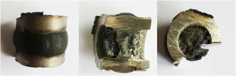
FIGURE 1. Picture of the blockage at the welded joint of the pipe (inner diameter: 10 mm) bellow adaptor in vessel 03.
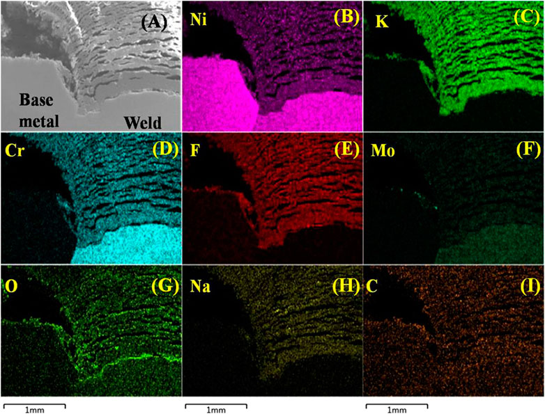
FIGURE 2. (A) Cross-sectional SEM image. (B–I) EDS elemental mapping image of the blockage at the welded joint of the pipe bellow adaptor in vessel 03.
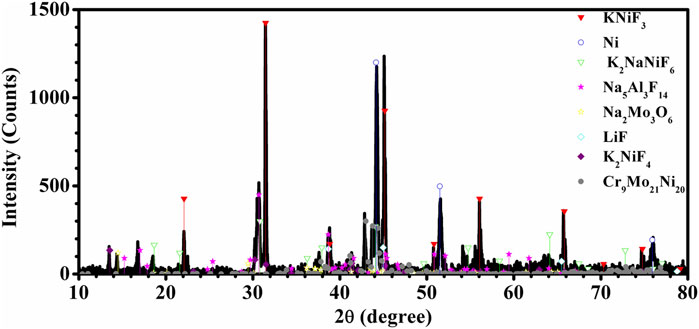
FIGURE 3. XRD pattern of the blockage at the welded joint of the pipe bellow adaptor in vessel 03.
X-ray can penetrate into the matter. The difference in density and atomic composition exhibits a different X-ray absorption coefficient, which results in the difference of the gray value in the X-ray radiographies at different scanning points. The shaded gray or black color is for low gray value, while the white color is for high gray value. The gray value is linearly related to the density of materials. X-ray CT is a non-destructive technique to image the internal feature of one object in three dimensions (Otani et al., 2010). Therefore, industrial 3D CT was employed to study the internal structure of pipes in the FLiNaK processing system. The 2D CT images in Figures 4A,B show that there is a layer-like structure in the blockage. The layered structure is consistent with the SEM image in Figure 2A. It appears that the alternate layers of depositions and cracks are like a layered structure. The alternate layers of depositions and cracks should be related to the periodic transportation of molten salt between different vessels. The 3D CT image in Figure 4C shows that the welded pipe is almost fully blocked at the inner of the weld. Therefore, the mixed H2/HF sparging gas cannot come into the vessel, and molten salt cannot be transferred between the different vessels. To unveil the puzzle, the blockage and the salt that adhered to the blocked pipe were removed by using image processing, and the result is shown in Figure 4D. It can be clearly seen that there is a welding defect at the backside of the weld. It is a typical incomplete root penetration which is a failure of the weld metal to penetrate into the root of a joint (Hughes and Matthews, 2009; Mandal and Mandal, 2017). It is worth noting that this defect occurs at all the backside for the half-girth weld. The incomplete root penetration defect can stop the transfer of precipitants in the terminal salt and then deposit on the welding defect area to result in the blocked pipe. Figure 5 shows the internal structure of another welding pipe above the adaptor in vessel 02 which was scanned by 3D CT as well. It is noteworthy that the internal surface of the girth weld is very smooth, and no welding defects and depositions were found on the inner surface of the pipe. A comparison of Figure 4 and Figure 5 indicates that the incomplete root penetration defect plays an important role in the blockage of the pipe. Thus, this kind of welding defect should be avoided in molten salt purification processing system and MSRs.
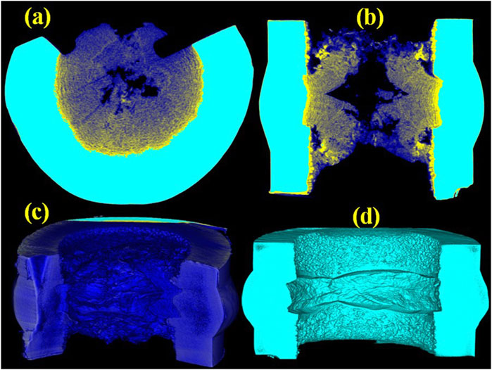
FIGURE 4. (A) Sagittal (yz) slice, (B) frontal (xz) slice, (C) 3D CT images of the blocked pipe bellow adaptor in vessel 03, and (D) 3D CT images of the blocked pipe after removing the blockage and salt that adhered to the surface of the pipe.
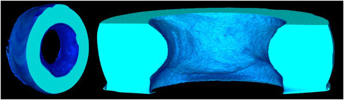
FIGURE 5. 3D CT images of the blocked pipe above the adaptor in vessel 02.
Several reasons can be usually ascribed to the incomplete root penetration defect (Hughes and Matthews, 2009; Mandal and Mandal, 2017). The first one is low welding current, which normally results in shallow penetration. The second one is the unreasonable design of the welding groove and gap, such as thick root face and narrow or too wide root gap, which results in the root being hard to penetrate. The third one is poor surface cleaning before welding or fast heat dissipation rate. A better solution to prevent the incomplete root penetration defect is employing a higher welding current and reasonable welding preparation. There should be filters in the molten salt processing system to remove the precipitants.
Figure 6 is a 3D CT image of the pipe which is immersed in salt in vessel 04, with the end of the pipe shown to be completely blocked. Therefore, the H2 sparging gas cannot come into the vessel to purify the molten fluoride salt, and the molten fluoride salt cannot be transferred between vessels. The origin of the blockage in the pipe immersed in salt in vessel 04 should be different from that in the pipe bellow adaptor in vessel 03. The structure of the blocked pipes is different. The blocked pipe immersed in salt in vessel 04 is a straight pipe, while the pipe bellow adaptor in vessel 03 is blocked at the welding site with inadequate root penetration. The environments in the pipe in vessel 04 and 03 are different. The pipe in vessel 03 was used to bubble with H2/HF to remove oxygen-containing and sulfur-containing impurities in molten FLiNaK salt and transfer the molten salt between vessels. The pipe in vessel 04 was for H2 to remove metallic ions in the molten FLiNaK salt. The vessels and pipes in the processing system are composed of metallic Ni. Impurities in raw fluoride salts and residual HF in molten salt can result in the corrosion of the Ni vessel to form NiF2. The results in Figure 3 indicate that NiF2 can react with KF and NaF to form K2NiF4, KNiF3, and K2NaNiF6. Ni-containing impurities in molten FLiNaK salt can affect the corrosion of nickel-based alloy by the following reaction: Ni2+ + Cr ⇄ Cr2+ + Ni (Briggs, 1964; Pavlík et al., 2015). Therefore, Ni2+ in molten fluoride salts should be removed by processing. It is known that H2 can reduce Ni2+ into metallic Ni. Therefore, the molten salt transferred into vessel 04 was purged with H2 to remove residual Ni2+ in it. The XRD pattern in Figure 7 shows that the blockage is mainly composed of metallic Ni, indicating that the blockage was induced by the deposition of Ni that was reduced by H2 in the molten salt.
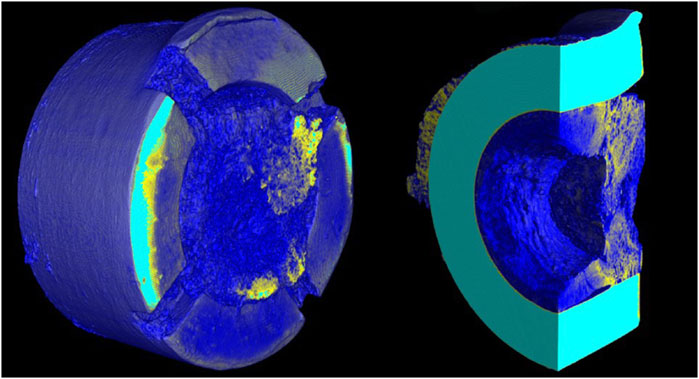
FIGURE 6. 3D CT images of the blocked pipe which was immersed in vessel 04.
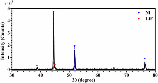
FIGURE 7. XRD pattern of the blockage in the pipe immersed in vessel 04.
Figure 8 is a diagram of the reactions in vessel 04. The salt in vessel 04 was processed with H2 by reaction 1). H2 and Ni2+ in the molten FLiNaK salt make up an electrochemical corrosion cell, where H2 at the end of the pipe in vessel 04 can be referred to as the anode and Ni2+ in the salt can be referred to as the cathode. The oxidation of H2 generates electrons [reaction (2)], while the reduction of Ni2+ consumes electrons [reaction (3)]. The metallic outlet pipe provides an electronic path for the movement of electrons from the anode to the cathode. The flow of current is from the cathode to the anode, which is opposite from the flow of electrons. Then, the current flows from the anode to the cathode by the movement of positively charged ions in the molten FLiNaK salt. At the H2 gas outlet, Ni2+ is reduced by H2 to form metallic Ni and deposited on the surface of the pipe. Ni2+ at the H2 gas outlet is consumed to form a concentration gradient of Ni2+ in the molten FLiNaK salt, which then results in the diffusion of Ni2+ in the molten FLiNaK salt towards the H2 gas outlet. As time goes on, Ni2+ in the molten FLiNaK salt will be removed little by little, and the deposition of metallic Ni results in the mouth of H2 gas outlet becoming narrower and narrower until the pipe is finally blocked.
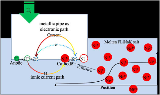
FIGURE 8. Diagram of the reactions in vessel 04.
The results shown above indicate that the blockage located at the end of the pipe immersed in salt in vessel 04 is mainly related to the reduction of Ni2+ by H2. Therefore, this kind of blockage should be avoided by decreasing the concentration of Ni2+ in salt and the amount of Ni2+-containing precipitants. The ratio of H2 and HF in the sparging gas should be controlled, and residual HF in molten salt should be removed by sparging with anhydrous helium to decrease the corrosion of the Ni vessel and then decrease the amount of Ni2+-containing corrosion products. Meanwhile, filters should be added in the processing system to remove Ni-containing precipitants from the molten salt.
Studies reveal that the failure of the LiF–NaF–KF processing system after a period of service is related to the blockage of pipes. The reasons and mechanism of blockage were studied in this paper. The main conclusions are as follows:
(1) One blocked area was found in the pipe at the welded joint of the pipe bellow adaptor in vessel 03, where the molten FLiNaK salt was processed with H2/HF. The blockage is mainly composed of KNiF3, Ni, K2NaNiF6, and K2NiF4. KNiF3, K2NaNiF6, and K2NiF4 are corrosion products of Ni vessel in the molten FLiNaK salt, while the metallic Ni is from the reduction of Ni2+ by H2 in the molten salt. The melting point of Ni, KNiF3, K2NiF4, and K2NaNiF6 is larger than the processing temperature. Therefore Ni, KNiF3, K2NiF4, and K2NaNiF6 in the terminal salt should be in the form of precipitants. The 3D industrial CT examination result indicates that the blockage at the welded joint of the pipe bellow adaptor in vessel 03 is mainly related to the incomplete root penetration defect which can stop the transfer of precipitants in the terminal salt. Therefore, welding defects, such as incomplete root penetration, in the molten salt processing system should be avoided.
(2) The other blockage occurred at the H2 gas outlet which is immersed in the molten FLiNaK salt in vessel 04, where the molten FLiNaK salt was processed with H2. The blockage is mainly composed of metallic Ni which should be attributed to the reduction reaction of Ni2+ by H2. The reduction of Ni2+ into metallic Ni produces a concentration gradient of Ni2+ in the molten FLiNaK salt and then drives the diffusion of Ni2+ toward the H2 gas outlet. Metallic Ni reduced from Ni2+ was deposited on the inner surface of the pipe at the gas outlet, which gradually caused the mouth of the H2 gas outlet to get narrower. Finally, the pipe was blocked. It should be possible to avoid this kind of blockage by decreasing the amount of Ni-containing corrosion products by controlling the ratio of H2 and HF in sparging gas and adding filters in the processing system.
The original contributions presented in the study are included in the article/Supplementary Material. Further inquiries can be directed to the corresponding authors.
XZ, LX, and JW contributed to conception and design of the study. SC organized the database. JF and MG performed the statistical analysis. HL and XY wrote the first draft of the manuscript. All authors contributed to manuscript revision and read and approved the submitted versions.
This work is supported by the National Key Research and Development Program of China (Grant Nos. 2017YFA0402800), Natural Science Foundation of Shanghai (Grant Nos. 17ZR1436600), and the “Transformational Technologies for Clean Energy and Demonstration,” Strategic Priority Research Program of the Chinese Academy of Sciences with Grants (Grant Nos. XDA 21000000).
The authors declare that the research was conducted in the absence of any commercial or financial relationships that could be construed as a potential conflict of interest.
All claims expressed in this article are solely those of the authors and do not necessarily represent those of their affiliated organizations, or those of the publisher, the editors and the reviewers. Any product that may be evaluated in this article, or claim that may be made by its manufacturer, is not guaranteed or endorsed by the publisher.
Ai, H., Shen, M., Sun, H., Dolan, K. P., Wang, C., Ge, M., et al. (2019). Effects of O2− Additive on Corrosion Behavior of Fe-Cr-Ni alloy in Molten Fluoride Salts. Corrosion Sci. 150, 175–182. doi:10.1016/j.corsci.2019.01.040
Briant, R. C., and Weinberg, A. M. (1957). Molten Fluorides as Power Reactor Fuels. Nucl. Sci. Eng. 2, 797–803. doi:10.13182/NSE57-A35494
Briggs, R. B. (1964). Molten-salt Reactor Program Semiannual Progress Report for Period Ending July 31, 1964. Report ORNL–3708. Oak Ridge National Laboratory. doi:10.2172/4676587
Engel, J. R. (1968). MSRE Design and Operations Report Part XI–A Test Program for 233U Operation. Report ORNL–TM–2304. Oak Ridge National Laboratory.
Field, P. E., and Shaffer, J. H. (1967). The Solubilities of Hydrogen Fluoride and Deuterium Fluoride in Molten Fluorides. J. Phys. Chem. 71 (10), 3218–3222. doi:10.1021/j100869a013
Grimes, W. R. (1967). Chemical Research and Development for Molten-Salt Breeder Reactors. Report ORNL–TM–1853. Oak Ridge National Laboratory.
Jardan, W. H., Cromer, S. J., and Miller, A. J. (1956). Aircraft Nuclear Propulsion Project, Quarterly Progress Report. Report ORNL–2157. Oak Ridge National Laboratory.
Jordan, W. H., Miller, A. J., and Savolainen, A. W. (1954). Aircraft Nuclear Propulsiion Project Quarterly Progress Report for Period Ending June 10, 1954. Report ORNL–1729. Oak Ridge National Laboratory.
Koger, J. W. (1972). Effect of FeF2 Addition on Mass Transfer in a Hastelloy N–LiF–BeF2–UF4 thermal Convection Loop System. Report ORNL–TM–4188. Oak Ridge National Laboratory.
Mandal, N. R. (2017). “Welding Defects,” in Ship Construction and Welding. Springer Series on Naval Architecture, Marine Engineering, Shipbuilding and Shipping. Singapore: Springer, Vol. 2. doi:10.1007/978-981-10-2955-4_19
Ocadiz-Flores, J. A., Capelli, E., Raison, P. E., Konings, R. J. M., and Smith, A. L. (2018). Thermodynamic Assessment of the LiF-NiF 2 , NaF-NiF 2 and KF-NiF 2 Systems. The J. Chem. Thermodynamics 121, 17–26. doi:10.1016/j.jct.2018.01.023
Otani, J., Watanabe, Y., and Chevalier, B. (2010). Introduction of X-ray CT Application in Geotechnical Engineering - Theory and Practice. IOP Conf. Ser. Mater. Sci. Eng. 10, 012089. doi:10.1008/1757-899X/10/1/01208910.1088/1757-899x/10/1/012089
Ouyang, F.-Y., Chang, C.-H., You, B.-C., Yeh, T.-K., and Kai, J.-J. (2013). Effect of Moisture on Corrosion of Ni-Based Alloys in Molten Alkali Fluoride FLiNaK Salt Environments. J. Nucl. Mater. 437, 201–207. doi:10.1016/j.jnucmat.2013.02.021
Pavlík, V., Kontrík, M., and Boča, M. (2015). Corrosion Behavior of Incoloy 800H/HT in the Fluoride Molten Salt FLiNaK + MFx (MFx = CrF3, FeF2, FeF3 and NiF2). New J. Chem. 39, 9841–9847. doi:10.1039/c5nj01839k
Robertson, R. C. (1965). MSRE Design and Operations Report Part I, Description of Reactor Design. Report ORNL–TM–728. Oak Ridge National Laboratory.
Rosenthal, M. W., Briggs, P. B., and Haubenreich, P. N., Molten-salt Reactor Program Semiannual Progress Report for Period Ending February 29, 1972, Report ORNL–4782 (1972).
S. E. Hughes, and C. Matthews (Editors) (2009). A Quick Guide to Welding and Weld Inspection. (Granta Park, Great Abington, Cambridge CB21 6AH, UK: Woodhead Publishing Limted, Abington Hall)..
Shaffer, J. H. (1971). Preparation and Handling of Salt Mixtures for the Molten Salt Reactor experiment. Report ORNL–4616. Oak Ridge National Laboratory. doi:10.2172/4074869
Sohal, M. S., Ebner, M. A., Sabharwall, P., and Sharpe, P. (2013). Engineering Database of Liquid Salt, Thermophysical and Thermochemical Properties. Report INL/EXT–10–18297. Idaho National Laboratory.
The U. S (2002). DOE Nuclear Research Advisory Committee and the Generation IV International Forum, A Technology Roadmap for Generation IV Nuclear Energy Systems. Report USDOE/GIG–002–00. Unite States Department of Energy.
Yin, H., Qiu, J., Liu, H., Liu, W., Wang, Y., Fei, Z., et al. (2018). Effect of CrF 3 on the Corrosion Behaviour of Hastelloy-N and 316L Stainless Steel Alloys in FLiNaK Molten Salt. Corrosion Sci. 131, 355–364. doi:10.1016/j.corsci.2017.12.008
Keywords: failure, molten fluoride salt, blockage, high temeprature, corrosion
Citation: Liu H, Chen S, Fu J, Yang X, Tang R, Ge M, Wang J, Zhou X and Xie L (2022) Study on the Mechanism of Failure in the LiF–NaF–KF Molten-Salt-Purifying Processing System. Front. Mater. 9:839538. doi: 10.3389/fmats.2022.839538
Received: 20 December 2021; Accepted: 05 January 2022;
Published: 15 February 2022.
Edited by:
Jie Qiu, Xi’an Jiaotong University, ChinaCopyright © 2022 Liu, Chen, Fu, Yang, Tang, Ge, Wang, Zhou and Xie. This is an open-access article distributed under the terms of the Creative Commons Attribution License (CC BY). The use, distribution or reproduction in other forums is permitted, provided the original author(s) and the copyright owner(s) are credited and that the original publication in this journal is cited, in accordance with accepted academic practice. No use, distribution or reproduction is permitted which does not comply with these terms.
*Correspondence: Xinmei Yang, eWFuZ3hpbm1laUBzaW5hcC5hYy5jbg==; Rui Tang, dGFuZ3J1aUBzaW5hcC5hYy5jbg==; Xingtai Zhou, emhvdXhpbmd0YWlAc2luYXAuYWMuY24=
Disclaimer: All claims expressed in this article are solely those of the authors and do not necessarily represent those of their affiliated organizations, or those of the publisher, the editors and the reviewers. Any product that may be evaluated in this article or claim that may be made by its manufacturer is not guaranteed or endorsed by the publisher.
Research integrity at Frontiers
Learn more about the work of our research integrity team to safeguard the quality of each article we publish.