
95% of researchers rate our articles as excellent or good
Learn more about the work of our research integrity team to safeguard the quality of each article we publish.
Find out more
ORIGINAL RESEARCH article
Front. Mater. , 10 January 2023
Sec. Mechanics of Materials
Volume 9 - 2022 | https://doi.org/10.3389/fmats.2022.1099610
This article is part of the Research Topic Design and Mechanical Failure of Deep-Sea Pressure Structures View all 6 articles
 Yu Wu1
 Youjie Li1
 Ruilong Luo1
 Zhonggang Zhang2,3*
 Fang Wang1*Bingxiong Zhao3,4
 Chao Yang5Jinfei Zhang1Oleg Gaidai1
Fully-transparent deep-sea pressure hulls have been attracted attention in recent years with the increasing demand for underwater observation. So far, public researches on design rule and failure modes for fully-transparent deep-sea pressure hulls are limited and the relevant experience cannot meet the requirements of new cabin design. In this study, the compression test is carried on, in which the material samples are subjected to quasi-static compressive load until failure in tests at different loading rates, and the hyperelastic finite element model is established in LS-DYNA software to simulate the failure process. Simulation results of material properties in finite element analysis on the cylindrical samples are compared with the experimental data, including the characteristic points of the mechanical properties in elastic stage and hardening stage, the ultimate load and failure mode of the samples. Mesh convergence analysis is conducted, and the appropriate mesh quality is accordingly selected in simulation of fully-transparent deep-sea pressure hulls. An equation for prediction of instability-type failure is described, which is derivation based on the classical analytical expression of elastic instability, thus, when 5 times of safety factor is taken, the wall thickness of the pressure hull is calculated to be t/R0 = 0.0685 at 2,500 m depth. Ultimate strength and failure mode of a typical fully-transparent deep-sea pressure hull are simulated. First, the first-order linear buckling modal analysis is carried out to simulate initial geometric imperfections. Then, simulations for the loading and collapse process of two fully-transparent pressure hulls respectively with one opening and two openings are conducted, and the ultimate load of 126 MPa and 128 MPa for the two kinds of hulls are obtained. Finally, simulation of a scaled pressure hull is carried out and simulation results are compared with the experimental data in reference, which are basically consistent. The calculated failure strength shows that the spherical hulls satisfy the safety factor requirement of 5 times. The provided simulation procedure can be referred for failure analysis of fully-transparent pressure hulls.
In recent years, more attention has been paid to deep ocean exploration, especially the research of manned submersible as an important tool. Pressure hulls made of titanium alloy or high-strength steel with transparent observation windows have been used as main parts of manned cabin. But the visual field of observation window is limited. To overcome the limitation, fully-transparent deep-sea pressure hulls were developed. Polymethylmethacrylate (PMMA) is a competitive plastic material for underwater engineering with its excellent optical clarity, superb colorability and color retention (Stachiw, 1986). In 1970, American Navy developed a submersible a with a fully-transparent spherical hull named NEMO (Snoey and Briggs, 1970; Stachiw, 1970), which proved the possibility of PMMA manned submersible. In Recent years, many fully-transparent acrylic manned cabins are manufactured and used in manned submersibles for panoramic visibility, such as Ocean Pearl and Triumph produced by SEA Magine Hydrospace, C-Quester made by U-Boat Worx (UBM), Handao Jiaolong developed by China Ship Scientific Research Center (Xu et al., 2022).
Safety is the first and essential concern for the underwater vehicles. Strength and deformation of the pressure hull under high pressure are quite important for integrated safety of the manned submersible. Thus, theoretical and numerical simulation studies have been conducted to study the ultimate strength and deformation:
In 1915, Zoelly et al. proposed theoretical calculation formula of buckling critical loads for ideal spherical hull under external pressure (Zoelly, 1915). Then Donnell et al. (Donnell and Wan, 1950), Koiter et al. (Koiter, 1945), Manuel et al. (Stein, 1964), Karman et al. (Karman and Tsien, 1941) and other scholars proposed non-linear large deflection theory, pre-buckling consistent theory, initial post buckling theory, which are main components of modern stability theory. Cui et al. (Pan and Cui, 2010; Pan et al., 2010) compared the design specifications of pressure spherical hull of submersible in different classification societies, and proposed an empirical formula for the critical load of titanium alloy pressure hull. In addition, observation window (Liu et al., 2010), manhole (Liu et al., 2016), welding effect (Yu et al., 2017) and initial deflection (Wang and Wan, 2014) of pressure hulls were studied. Based on these researches, a complete and mature metal pressure hull design standard has been formed (Rotter, 2011; Standard and GB 150, 2011). However, researches on design and failure form are rarely found for fully-transparent deep-sea pressure hulls, therefore new analysis procedures are needed. With the rapid development of computer science and finite element method (FEM), the failure behavior of structures can be predicted by finite element software. Walter performed a non-linear buckling analysis of spherical shell with initial defect, non-linearity material and non-linearity geometric model by numerical simulation (Walter and Ursula, 2002). George considered the non-linear effects of transverse shear deformation, initial curvature, stresses on the radial and thickness directions, and corrected the errors in the classical theory (George and Voyiadjis, 2004). Zhang et al. proposed buckling analysis of special shaped pressure hull (Zhang et al., 2018a; Zhang et al., 2019; Zhang et al., 2022), and the non-linear buckling of hulls geometrical defects were evaluated by developing modified Riks Method for modeling simulation (Zhang et al., 2018b). The creep and damage of PMMA viewport windows in the deep-sea manned submersible were also investigated by simulation approaches. Li et al. predicted the cyclic creep behaviors and lifetime of conical/spherical viewport windows by FEM simulation, in considerations of velocity, time, depth and sequence for diving (Li et al., 2021). Liu et al. developed characterization method on PMMA material properties by employed the ABAQUS-UMAT package (Liu et al., 2020). Wang et al. proposed an explicit formula to calculate the axial displacement of PMMA frustums with different ratios of thickness to diameter under different holding-time and pressures, to provide guidelines on the preliminary design of deep-sea window (Wang et al., 2021).
In this study, the compression test is carried on, material samples are subjected to quasi-static compressive load in failure tests at different loading rates, and the hyperelastic finite element analysis model is established in LS-DYNA software. Mesh convergence analysis is conducted, the appropriate mesh quality is selected in simulation of fully-transparent deep-sea pressure hulls. A equation for prediction of instability-type failure is described, which is derivation based on the classical analytical expression of elastic instability, and the wall thickness of the pressure hull is calculated. Ultimate strength and failure mode of a typical fully-transparent deep-sea pressure hull are simulated. Initial geometric imperfections, ultimate load and failure mode are obtained. The provided simulation procedure can be referred for failure analysis of fully-transparent pressure hulls.
The material test was carried out in accordance with ASTM D695-15 Standard test Method for Compressive Properties of Rigid Plastics and GB-T1041-2008 Determination of Compressive Properties of Plastics. PMMA samples with diameter of 12.7 mm and length of 25.4 mm were subjected to quasi-static compressive load in failure tests at different loading rates (0.5 mm/min, 5 mm/min, 10 mm/min, 50 mm/min and 100 mm/min for the samples Z01, Z02, Z03, Z04, Z05 respectively). The test pressurization process, with the recorded stress-strain curve and photo of the sample after destruction is shown in Figure 1. The compression failure test is carried on the testing machine TSE105D, compression force is set. The compression force and displacement are recorded as shown in Figure 2. The corresponding stress and strain curve are calculated according to σ = F/A0, ε = Δl/l0, where, F is compression force, A0 is minimum cross-sectional area of the sample, Δl is compression displacement of the sample, and l0 is original length of the sample. Details of material properties obtained by the compressive tests are listed in Table 1. It is shown that (1) the elastic stage of PMMA material quickly turns into the non-linear stage at the second half of the period before the yield point. Therefore, the properties of material cannot be described by the traditional linear elastic analysis method; 2) the elastic modulus and yield strength increase with the loading rate; 3) the fracture strength and fracture strain increase with the loading rate.

FIGURE 1. Experimental test process.
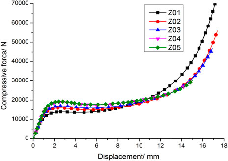
FIGURE 2. Compressive force-displacement curves at different loading rates.
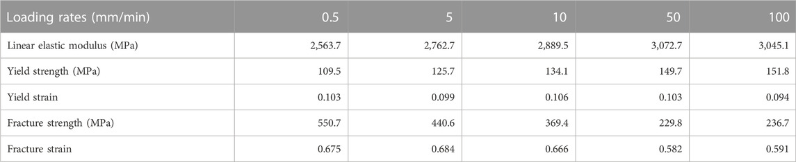
TABLE 1. The results of compression test.
The plastic deformation of PMMA after yielding was measured at the condition of loading rate V = 0.5 mm/min, and the samples were loaded to the upper yield, intermediate yield and lower yield respectively and then unloaded. The strain of samples with time is shown in Figure 3. It is shown that the deformation can be completely recovered after loading to the upper yield point, while certain permanent deformation is produced at the intermediate yield point and lower yield point. It shows that the process from upper yield to lower yield is a process from elasticity to plasticity.
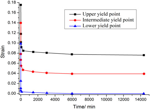
FIGURE 3. Strain curves of PMMA specimens after elastic unloading.
The hyperelastic finite element analysis model is established in LS-DYNA software by fitting the relevant parameters with the test data. The loading rate of 0.5 mm/min is set. The geometric parameters and the boundary conditions are the same as the test conditions. Mesh convergence analysis is conducted by comparing the finite element analysis results with the experimental data. The stresses of samples at 0.049898 m, 0.44998 m, 0.75 m, 0.79995 m, 0.84995 m and 1.6 m are shown in Figure 4. It can be seen that the fracture occurs when the maximum stress of the sample reaches 145 MPa. The trend of stress-strain curve is related to mesh size. The stress-strain curves at different mesh sizes are shown in Figure 4, in which the curves represent the conditions of the mesh sizes that are equal to 0.2 mm, 0.5 mm and 0.9 mm. When the meshing becomes denser, the calculation results of stress-strain curves also tend to experiment result. But their values differences are very small, the grid strains at fracture are 1.56, 1.57 and 1.60 respectively. Mesh size 0.2 mm is determined for compression simulation of sample. A huge number of elements will lead to a large amount of computer resource requirements. Therefore, mesh size 0.9 mm is determined for simulation of fully-transparent deep-sea pressure hulls.
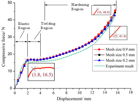
FIGURE 4. Stress curve in finite element analysis.
Conclusions drawn by Figure 4 include 1) the elastic stage of PMMA material quickly turns into the non-linear stage; 2) the elastic modulus and yield strength increase with the loading rate; 3) the fracture strength and fracture strain increase with the loading rate. The finite element analysis results are compared with the experimental data. In the elastic stage, the yield of the material in the experiment and finite element analysis occur respectively at (2 mm, 17 kN) and (1.8 mm, 16.5 kN); And in the hardening stage, the result from finite element anlaysis ends at the point (1.6 mm, 48 kN) comparing to that of experimental result at the point (1.6 mm, 45 kN).
Figure 5 depicted the stress nephogram of sample. As can be seen, the cylinder sample bulges in the middle under pressure, and then breaks under the action of tension, which conforms to the experiment.
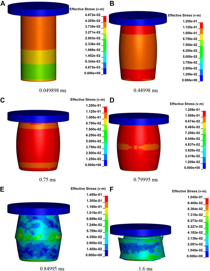
FIGURE 5. Stress nephogram of sample. (A) 0.049898 ms (B) 0.44998 ms, (C) 0.75 ms (D) 0.79995 ms, (E) 0.84995 ms (F) 1.6 ms.
The classical analytical expression for elastic instability developed by Zoelly, can be written as below (Krenzke and Kiernan, 1741)
Where, Pcr is critical pressure at which elastic instability occurs; E is Young’s modulus; t is shell thickness; μ is Poisson’s ratio; K is buckling coefficient; Rm is radius to midsurface of shell.
The pressure structure cannot be perfectly spherical hull. It is found that the critical pressure predicted by the classical small deflection theory of elastic instability is 20%–30% higher than the experimental collapse pressure of spherical hull.
As subsequent research has shown that the deviation of experimental collapse pressure from the calculated critical pressure for perfect spheres is a function of deviations from nominal sphericity and nominal wall thickness, attempts were made to modify the classical formula. The resulting semiempirical expression (Krenzke and Kiernan, 1741):
R0 is inner diameter of pressure hull.
To make this equation applicable to acrylic material one further modification is necessary. In place of Young’s modulus E based on the linear relationship between stress and strain, new terms must be substituted that reflect the non-linear relationship between stress and strain in acrylic material. The new term for E may be the tangent modulus of elasticity (Et), secant modulus of elasticity (Es), or a hybrid expression of
The secant modulus, tangent modulus, and variable Poisson’s ratio are generally derived from typical uniaxial-compression stress-strain curves of acrylic test specimens. In order to arrive at the stress level in the sphere so that the proper Es, Et and μv can be substituted into Equation (2) the following simplified equation is use
A new equation for prediction of instability-type failure in PMMA shells can be expressed as
It is assumed that the water depth is 2,500 m, the water pressure is 25 MPa, 5 times of safety factor is taken, the wall thickness of the pressure hull is calculated to be t/R0 = 0.0685. Thus, the dimensions of the pressure hull with a depth of 2,500 m are determined as shown in Figure 6.
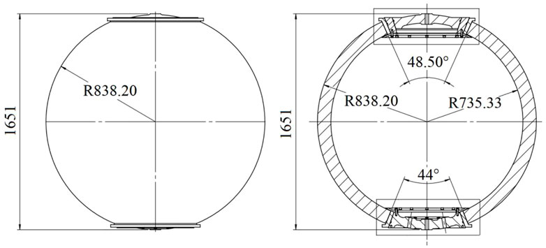
FIGURE 6. Structural diagram of fully transparent pressure hull.
Geometric model in finite element software is shown in Figure 7. The inner diameter of the pressure hull is 1,470.66 mm, the outer diameter is 1,676.4 mm. The upper hole is manhole, and the lower hole is installation and wiring hole. The finite element model is established using LsDyna software. The pressure hull is made of PMMA. The hole cover is made of steel. The elastic modulus is set as 210,000 MPa, and the density is set as 7.8 g/cm³. The three-points constraint specified by China Classification Society is selected: Uy = Uz = 0, Ux = Uz = 0 and Uy = Uz = 0.
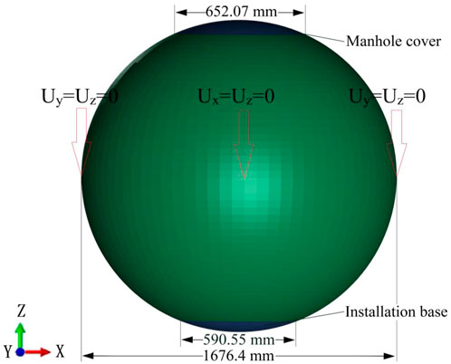
FIGURE 7. Geometric model and constraint in finite element software.
The pressure of 1.0 MPa is applied to the outer surface of pressure hull. The buckling analysis is based on the static analysis, therefore the static analysis is carried out first, and the first-order modal analysis is implemented based on the static result. The buckling of fully-transparent pressure hull with double holes is obtained as shown in Figure 8.
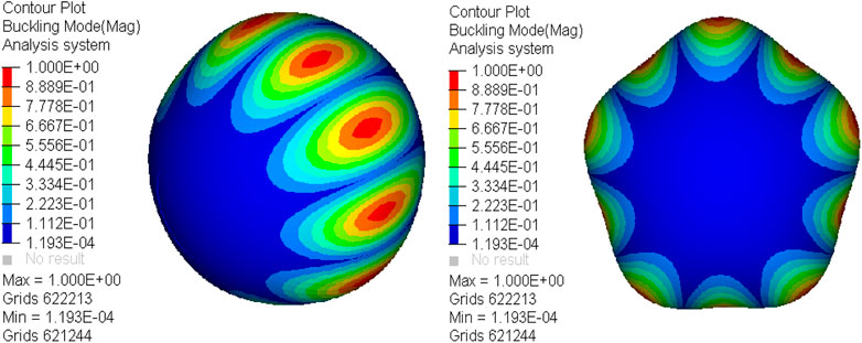
FIGURE 8. First order linear buckling analysis of pressure hull.
The collapse process is simulated. The load is applied to the surface of spherical hull with the loading rate in sample simulation. According to the fracture strain in experiment and mesh parameters in sample simulation, the collapse process of fully-transparent pressure hull with one and two holes are shown in Figure 9 and Figure 10.
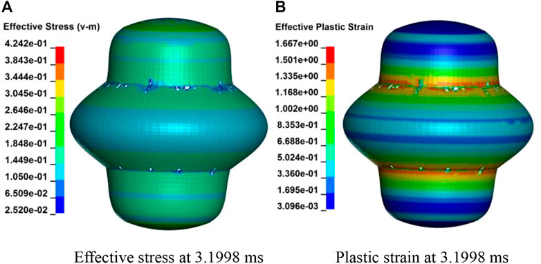
FIGURE 9. Fully-penetration pressure hull with two holes. (A) Effective stress at 3.1998 ms (B) Plastic strain at 3.1998 ms.
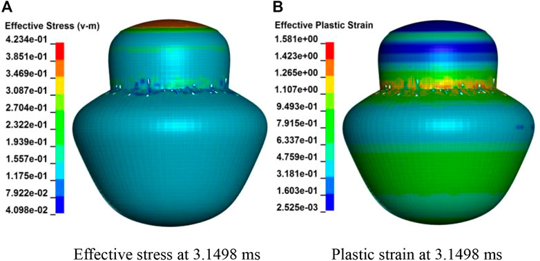
FIGURE 10. Fully-transparent pressure hull with one hole. (A) Effective stress at 3.1498 ms (B) Plastic strain at 3.1498 ms.
The effective stress and plastic strain of fully-transparent pressure hull with two holes at loading time 3.1998 m are shown in Figure 9. When the spherical hull is subjected to an external load, stress concentration occurs in the local reinforced part. When the pressure increases to 127.992 MPa, it begins to damage until the upper and lower hemispheres are completely broken.
The effective stress and plastic strain of fully-transperent pressure hull with one hole at loading time 3.1498 m are shown in Figure 10. When the spherical hull is subjected to an external load, stress concentration occurs in the local reinforced part. When the pressure increases to 125.992 MPa, it begins to damage until the upper hemisphere is completely broken.
When the water pressure is 25 MPa, for spherical hull with double holes, the ultimate load is 127.992 MPa. And for spherical hull with one hole, the ultimate load is 125.992 MPa. They all meet the design requirement of 5 times safety factor. Therefore, ratio of thickness to radius of pressure hull t/R0 = 0.0685 meets the design requirements of the pressure hull operation at 2,500 m depth.
It is difficult to verify the accuracy of finite element analysis through large-sized pressure hull in laboratory. Therefore, simulation of scaled pressure hull is carried out. The inner diameter of the sample pressure hull is 220 mm, and the outer diameter is 250.14 mm in present study.
The effective stress and plastic strain of scaled pressure hull at loading time 1.54 m are shown in Figure 11. When the spherical hull is subjected to an external load, stress concentration occurs in the local reinforced part. When the pressure increases to 31.2 MPa, it begins to damage until the upper hemisphere is completely broken. The simulation results are compared with the experimental results in reference (Xu et al., 2022). Pressure hull at the same size is crushed when the load increases to 27.5 MPa, and the relative error between the finite element analysis result and the experimental result is 13.45%, which is basically consistent.
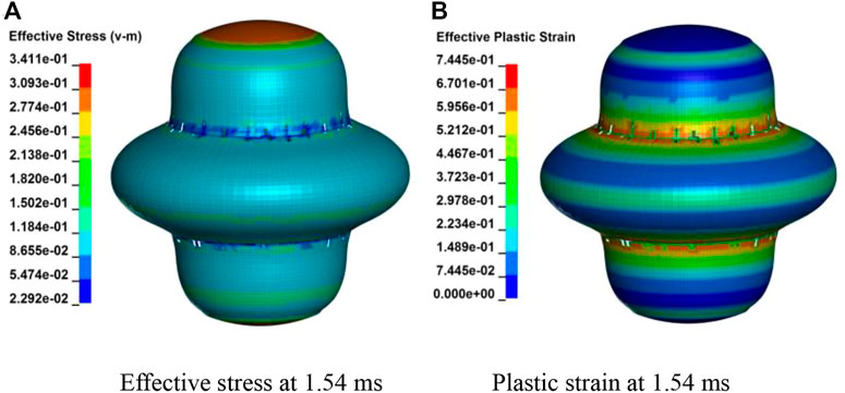
FIGURE 11. Fully-transparent sample pressure hull. (A) Effective stress at 1.54 ms (B) Plastic strain at 1.54 ms.
In this paper, the failure mode and buckling behavior of fully-transparent pressure hull are studied. The finite element model is established in LS-DYNA software by fitting the relevant parameters with the data from compressive tests of PMMA sample. The failure mode is consistent with experiment data, and mesh size in finite element model is determined based on convergence analysis. It is assumed that the water depth is 2,500 m and the water pressure is 25 MPa, taking 5 times of safety factor, the wall thickness of the hull is calculated to be t/R0 = 0.0685. The first-order modal analysis is carried out on the static result, and the buckling of the fully-transparent pressure hull is obtained. The collapse process is simulated. The load is applied to the outer surface of the spherical hull according to the loading rate of sample simulation. According to the fracture strain in experiment and mesh parameters in sample simulation, the collapse process of fully-transparent pressure hull with two and one holes are obtained. When the pressure increases to 128 MPa and 126 MPa respectively, the hulls begin to damage until they are completely broken. When the water pressure is 25 MPa, they all meet 5 times safety factor. At the same time, simulation of scaled pressure hull is carried out. The simulation results are compared with the experimental results in reference, which is basically consistent. Therefore, ratio of thickness to radius t/R0 = 0.0685 meets the design requirements of the pressure hulls operation at 2,500 m depth (Stachiw, 1971).
The original contributions presented in the study are included in the article/supplementary material, further inquiries can be directed to the corresponding authors.
Conceptualization, YW; methodology, YL; software, ZZ; validation, FW; formal analysis, BZ; investigation, CY; resources, JZ; data curation, RL; writing—original draft preparation, YW, CY; writing—review and editing, OG; supervision, ZZ; project administration, FW; funding acquisition, YW. All authors have read and agreed to the published version of the manuscript.
This work is supported by the National Key Research and Development Program of China (Grand No. 2021YFC2800600), the Open Fund of Fujian Province Key Laboratory of Ship and Ocean Engineering, National Natural Science Foundation of China (Grant Nos. 52071203 and No. 52101320), Natural Science Foundation of Fujian Province (2022J01807).
The authors would like to express their gratitude for the support of Fishery Engineering and Equipment Innovation Team of Shanghai High-level Local University.
The authors declare that the research was conducted in the absence of any commercial or financial relationships that could be construed as a potential conflict of interest.
All claims expressed in this article are solely those of the authors and do not necessarily represent those of their affiliated organizations, or those of the publisher, the editors and the reviewers. Any product that may be evaluated in this article, or claim that may be made by its manufacturer, is not guaranteed or endorsed by the publisher.
Donnell, L. H., and Wan, C. C. (1950). Effect of imperfections on buckling of thin cylinders and columns under axial compression. J. Appl. Mech. 17 (1), 73–83. doi:10.1115/1.4010060
George, Z., and Voyiadjis, P. W. (2004). A refined theory for thick spherical shells. Int. J. Solids Struct. 41, 3747–3769. doi:10.1016/j.ijsolstr.2004.02.022
Karman, Von T., and Tsien, H. S. (1941). The buckling of thin cylindrical shells under axial compression. J. Aeronaut. Sci. 8 (8), 303–312. doi:10.2514/8.10722
Koiter, W. T. (1945). “On the stability of elastic equilibrium, thesis presented to the Technical University at Delft, Amsterdam, The Netherlands,” in Partial fulfillment of the requirements for the degree of doctor of philosophy. English translation. NASA tech (Delft, Holland: Ph. D. Dissertation).
Krenzke, M. A., and Kiernan, T. J. (1963). Tests of stiffened and unstiffened machined spherical shells under extemal hydrostatic pressure. David Taylor Model Basin Report.ASME New York, New York, United States
Li, J. X., Liu, P. F., and Tong, X. Y. (2021). A simplified method for studying cyclic creep behaviors of deep-sea manned submersible viewport windows. Int. J. Press. Vessels Pip. 194, 104565. doi:10.1016/j.ijpvp.2021.104565
Liu, D. Q., Hu, Yong, Wang, F., Tian, C. L., and Cui, W. C. (2010). Mechanics analysis on deepsea human occupied vehicle’s viewport windows. Eng. Index J. 14 (7), 782–788.
Liu, F., Han, D., and Yao, J. (2016). Robust optimization of a pressure spherical shell with a strengthened opening. J. Harbin Eng. Univ. 37 (12), 16131637–16141618. doi:10.1016/j.ijmecsci.2018.03.029
Liu, P. F., Li, J. X., Wang, S. B., and Leng, J. X. (2020). Finite element analysis of viscoelastic creep behaviors of deep-sea manned submersible viewport windows. Int. J. Press. Vessels Pip. 188, 104218. doi:10.1016/j.ijpvp.2020.104218
Pan, B. B., and Cui, W. C. (2010). An overview of buckling and ultimate strength of spherical pressure hull under external pressure. Marine Structures.23, (3), 227-240. doi:10.1016/j.marstruc.2010.07.005
Pan, B. B., Cui, W. C., Shen, Y. S., and Liu, T. (2010). Further study on the ultimate strength analysis of spherical pressure hulls. Mar. Struct. 23 (4), 444–461. doi:10.1016/j.marstruc.2010.11.001
Rotter, Michael J. (2011). The new framework for shell buckling design and the European shell buckling recommendations fifth edition. J. Press. Vessel Technol. 133 (1), 011203. doi:10.1115/1.4002565
Snoey, M. R., and Briggs, E. M. (1970). The NEMO submersible. ASME Paper 70-Unt-C.New York, New York, United States
Stachiw, J. D. (1970). Development of a spherical acrylic plastic pressure hull for Hydrospace applications. Naval Civil Engineering Laboratory.Port Hueneme, Calif Technical Report R-676, 707363.
Stachiw, J. D. (April 1986). Origins of acrylic plastic submersibles. Origins of acrylic plastic submersibles. Proceedings of the 2004 International Symposium on Underwater Technology (IEEE Cat. No.04EX869), Taipei, Taiwan
Stachiw, J. D. (1971). Spherical acrylic pressure hulls for undersea exploration. J. Eng. Industry 93, 731–750. doi:10.1115/1.3427992
Standard, Chinese, (2011) GB 150 (2011).Standard, Chinese, Design of pressure vessels.mainland China
Stein, M (1964). The influence of prebuckling deformations and stresses on the buckling of perfect cylinders Washington, DC, 190. NASA Tr.
Walter, W., and Ursula, A. (2002). Buckling behavior of imperfect spherical shells. Int. J. Non-Linear Mech.,12 569–604.doi:10.1016/S0020-7462(01)00086-5
Wang, D., and Wan, Z. Q. (2014). Simplified calculation formula for critical load of spherical pressure shell considering the influence of initial shape. Eng. Index J. 18 (5), 557–564.
Wang, F., Wang, M. Q., Wang, W. W., Yang, L., and Zhang, X. Z. (2021). Time-dependent axial displacement of PMMA frustums designed for deep-sea manned cabin based on finite element analysis. Ships Offshore Struct. 16 (8), 827–837. doi:10.1080/17445302.2020.1786235
Xu, S. X., Gao, H. X., Qiu, P., Shen, W., Cai, Y., and Liu, D. Y. (2022). Stability analysis of acrylic glass pressure cylindrical shell considering creep effect. Thin-Walled Struct. 1812, 110033. doi:10.1016/j.tws.2022.110033
Yu, C. L., Chen, Z. T., Chen, C., and Chen, Y. T. (2017). Influence of initial imperfections on ultimate strength of spherical shells. Int. J. Nav. Archit. ocean Eng. 9 (5), 473–483. doi:10.1016/j.ijnaoe.2017.02.003
Zhang, J., Wang, M. L., Tang, W. X., Wang, F., and Hua, Z. (2018). Effect of thickness on the buckling strength of egg-shaped pressure hulls. Ships Offshore Struct. 13 (4), 375–384. doi:10.1080/17445302.2017.1389253
Zhang, J., Wang, R., Li, Y., Wang, W., and Wu, W. (2022). Numerical and experimental buckling of segmented spiral pressure hulls. J. Mech. Sci. Technol. 36 (4), 1799–1807. doi:10.1007/s12206-022-0316-2
Zhang, J., Zhang, M., Pan, B. B., Tang, W., and Wang, F. (2018). Elastic-plastic buckling of deep sea spherical pressure hulls. Mar. Struct. 57, 38–51. doi:10.1016/j.marstruc.2017.09.007
Zhang, J., Zhang, Y., Wang, F., Zhu, Y., Cui, W., Chen, Y., et al. (2019). Experimental and numerical studies on the buckling of the hemispherical shells made of maraging steel subjected to extremely high external pressure. Int. J. Press. Vessels Pip. 172, 56–64. doi:10.1016/j.ijpvp.2019.03.016
Keywords: fully-transparent, deep-sea, pressure hull, failure, finite element analysis
Citation: Wu Y, Li Y, Luo R, Zhang Z, Wang F, Zhao B, Yang C, Zhang J and Gaidai O (2023) Failure analysis on fully-transparent deep-sea pressure hulls used at 2,500 m depth. Front. Mater. 9:1099610. doi: 10.3389/fmats.2022.1099610
Received: 16 November 2022; Accepted: 21 December 2022;
Published: 10 January 2023.
Edited by:
Yu Zhang, China University of Petroleum, ChinaReviewed by:
Ke Liang, Northwestern Polytechnical University, ChinaCopyright © 2023 Wu, Li, Luo, Zhang, Wang, Zhao, Yang, Zhang and Gaidai. This is an open-access article distributed under the terms of the Creative Commons Attribution License (CC BY). The use, distribution or reproduction in other forums is permitted, provided the original author(s) and the copyright owner(s) are credited and that the original publication in this journal is cited, in accordance with accepted academic practice. No use, distribution or reproduction is permitted which does not comply with these terms.
*Correspondence: Zhonggang Zhang, emhnYW5nMDUzMEAxNjMuY29t; Fang Wang, d2FuZ2ZhbmdAc2hvdS5lZHUuY24=
Disclaimer: All claims expressed in this article are solely those of the authors and do not necessarily represent those of their affiliated organizations, or those of the publisher, the editors and the reviewers. Any product that may be evaluated in this article or claim that may be made by its manufacturer is not guaranteed or endorsed by the publisher.
Research integrity at Frontiers
Learn more about the work of our research integrity team to safeguard the quality of each article we publish.