 Yong Wang1
 Gang-feng Yang
- 1School of Civil and Resource Engineering, University of Science and Technology Beijing, Beijing, China
- 2School of Materials Science and Engineering, Zhengzhou University, Zhengzhou, China
- 3Zhengzhou Special Flux Materials Co., Ltd., Zhengzhou, China
Wear resistance is one of the most important performance indicators of filling pipelines, but there are few studies on its quantitative test and life prediction. In this paper, an experimental device and its application method for testing the wear resistance of the pipeline are proposed, and the device is used to test the wear resistance of the self-developed lining composite pipeline, the traditional 16 Mn steel pipeline and the ordinary carbon structural steel pipeline. The results show that the wear resistance of the composite lining material is 12.35 times of that of 16 Mn steel and 7.32 times of that of ordinary carbon structural steel. The wear resistance mechanism is analyzed from the perspective of the material composition of the composite liner, mainly because the composite liner material uses fused alumina grain sand, silicon carbide and other extremely wear-resistant materials with high hardness as aggregate, and the aggregates are spherical or nearly spherical particles, with smooth surface and small friction resistance. Finally, through a comparison engineering application of a certain iron ore concentrate transportation. Compared with the traditional 16 Mn steel pipeline, the composite lined pipeline has been used for more than 5 years without any problems, while the traditional 16 Mn steel pipeline is worn through within 1 year. Engineering application shows that the composite lined pipeline has good wear resistance, and it also confirms the reliability of the detection method proposed in this paper.
Introduction
The technology of full tailings filling mining can use the surface tailings to the maximum extent and is widely used in mines at home and abroad (Ghirian and Fall 2013; Wu et al., 2016; Wu et al., 2018). Pipeline transportation is considered as the “throat” project of filling mining technology, which plays a very important role in filling technology. However, in actual filling, it often encounter that the filling pipe wears through, resulting in the construction of the drilled hole having to be discarded in a shorter time (Mao et al., 2018; Shi et al., 2020). Therefore, serious wear and short service life of the filling pipeline is one of the main problems faced by the mine filling, causing serious economic losses and affecting production efficiency. There are two main reasons for this phenomenon: one is that it is difficult to predict the wear resistance of the filling pipe before it is used; on the other hand, the wear resistance of the pipe material itself is poor.
At present, much research has been carried out on pipeline wear at home and abroad. A variety of wear-resistant pipes have been researched in China (FU et al., 2017), including single material pipes and composite pipes. Among them, surfacing composite pipes (Deng et al., 2013; Wang et al., 2016) and bimetallic composite pipes (Li et al., 2011; Wang et al., 2013; Cao et al., 2014; Wang et al., 2015) have good comprehensive performance and long service life, and are increasingly used in domestic mines. For the research of pipeline wear, there are mainly two methods: experimental analysis and numerical simulation. The main methods of pipe wear test in China are rotary motion test and loop pipe simulation test (Zou et al., 2004). Rotary motion test is to put the test grinding block in the slurry for circular motion, and its wear resistance is characterized by the amount of metal loss of the grinding block. Loop pipe simulation test is to test the pipeline wear resistance by simulating the actual situation of pipeline transportation. The above two methods have long test cycles, less wear in a short time, and it is difficult to quickly define the wear resistance of the pipeline. Numerical simulation is mainly based on the theory of solid-liquid two-phase flow, through CFD, FLUENT fluid mechanics and fluid dynamics module of Ansys software, the discrete particle model (DPM) (Guo and Zhang, 2015), Mixture mixed model (Wu et al., 2019) and dense discrete phase model (DDPM) (Liu et al., 2015) on the simulation analysis under different conditions of pipeline wear. The wear of different parts of the pipeline, the influence of different flow rate and particle size on the wear of the pipeline can be obtained. The numerical simulation is focusing more on the identification of the easy-wearing pipe section, and there is less research on the wear resistance of the pipeline itself.
According to the definition of the American Material Test, foreign scholars have found that elastomer materials can absorb the elastic deformation caused by the wear medium and make their plastic deformation small, but their use has certain limitations (Xie et al., 2015). For many years, foreign countries have tested pipeline wear by jet impact tester (SimonLi et al., 1981), Coriolis wear tester (Chandel, 2010) and tank wear tester (Tsai et al., 1981), which are used to evaluate the properties of pipe materials under different conditions and discuss the dependence of wear on relative velocity, impact angle and solid concentration (Rawat et al., 2017). Using the ASTM G65-04 wear tester (Hewitt et al., 2009) for wear resistance testing can quickly determine the on-site pipeline wear performance.
In conclusion, foreign countries have established relevant standards for pipeline wear resistance testing, but China’s research in this field is relatively backward, leading to engineering analogy for pipeline product selection and life evaluation, with certain limitations and blindness. If the wear resistance can be quantitatively evaluated before filling pipeline is selected, it will reduce the risk of selection of mine pipeline, save the cost of pipe and prolong the service life of borehole. To this end, this paper proposes a rapid testing device for pipeline wear performance, and compares the wear resistance of a self-developed pipeline material with commonly used 16 Mn steel and ordinary carbon steel. And through the iron ore concentrate transportation pipeline with higher wear resistance requirements for engineering verification, the wear resistance of the new composite pipeline and the reliability of the wear resistance test method were verified.
Device and Method
Experimental Device
For the measurement of the wear resistance of pipeline materials, we have independently developed a wear resistance test device. The main body of the device is composed of the base cabinet, supporting table, protective cover, rotating iron disc, waterproof gauze, waterproof gauze fixing device, fixed shaft, motor, pipe material fixing bracket, pipe material, adding water pipe and counterweight material, as shown in Figure 1. The base cabinet is located at the bottom of the whole device, the supporting table is fixed on the upper surface of the base cabinet, the protective cover is fixed on the top of the supporting table, and the rotating iron disc is placed inside the protective cover. Waterproof gauze is paved on the surface of the rotating iron disc, waterproof gauze fixing device is located on the surface of the side wall of the rotating iron disc, the fixed shaft is fixed on the base cabinet, through the support table, connected to the rotating iron disc, the motor is placed in the base cabinet. The pipe material fixing bracket is fixed on the supporting table wall, the pipe material is fixed on the side of the pipe material fixing bracket, the water-adding pipe is located above the boundary between the waterproof gauze and the pipe material, and the counterweight material is above the pipe material.
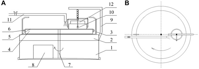
FIGURE 1. Front view (A) and top view (B) of the wear resistance test device for filled pipes (In the picture, 1- Base cabinet; 2- Support table; 3- Protective cover; 4- Rotating iron disc; 5- Waterproof gauze; 6- Waterproof gauze fixing device; 7- Fixed shaft; 8- Motor; 9- Pipe material fixing bracket; 10- Pipe material; 11- Add water pipe; 12- Counterweight material).
The device is small in size and flexible in movement, and can be tested in the laboratory or in the field. Abrasion resistance testing can be performed on various pipelines before on-site pipeline selection, which provides a basis for later on-site pipeline selection and has strong practical value.
Testing Method
In this study, three pipeline materials were selected, including commonly used 16 Mn steel materials, ordinary carbon structural steel materials, and self-developed composite wear-resistant materials. The performance of the self-developed wear-resistant materials is shown in Table 1.
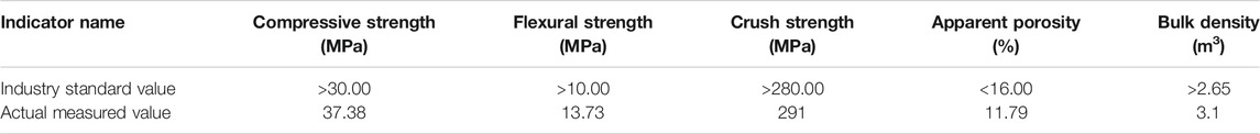
TABLE 1. Performance indicators of self-developed wear-resistant materials.
Firstly, the measured pipeline material is fixed in the middle of the disk radius on the side of the pipeline material fixation bracket, and is closely attached to the surface of the waterproof gauze. The counterweight material is placed above the tested wear-resisting pipeline material, and the rotating shaft speed is set at 1,000 r/min, with a certain pressure. Turn on the motor, the waterproof gauze is rotated by rotating the iron disc to wear down the lower surface of the pipeline material. Wear the test material for 1 h, and smooth its surface. At this time, the mass of the pipeline material after drying is
In the formula,
Using the above method, the wear thickness of the self-developed wear-resistant material is
Results and Analysis
In order to ensure the reliability of the experiment, two tests are performed on the new composite material wear-resistant pipeline, and the average value is taken. The wear thickness is compared with the wear of 16 Mn steel and ordinary carbon structural steel materials. In order to ensure the comparability of the test results, although the area of the tested materials is different, the pressure of the counterweight remains basically the same during the test. The test uses sandpaper model BYZ62-P40. The test results are shown in Table 2, and the comparison of wear thickness of different materials is shown in Figure 2. It can be seen from Table 2 and Figure 2 that the average value of the two wear thicknesses of the new wear-resistant material is 0.1314 mm. The wear thicknesses of 16 Mn steel and ordinary carbon structural steel are 1.6232 and 0.9612 mm, respectively. The wear thickness of 16 Mn steel is 12.35 times that of wear-resistant lining materials, and the wear thickness of ordinary carbon structural steel is 7.32 times that of wear-resistant lining materials. It can be seen that the wear resistance of the new wear-resistant pipeline lining material is significantly better than that of 16 Mn steel and ordinary carbon steel materials. Figure 3 shows the comparison between a wear-resistant lining material and 16 Mn steel before and after the test. As can be seen from Figure 3, under the same pressure and time wear conditions, the wear degree of 16 Mn steel sample is more serious, and the sample morphology changes significantly with that before wear, while the sample morphology of the new wear-resistant material shows little difference with that before wear.
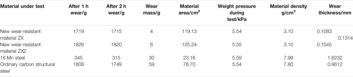
TABLE 2. Test results of wear resistance.
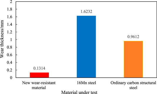
FIGURE 2. The comparison of wear thickness of different materials.
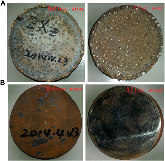
FIGURE 3. Comparison of before and after wear of pipe samples [(A): new wear-resistant materials; (B): 16 Mn steel materials].
It can be seen from Table 2 that the wear resistance of the new wear-resistant materials is significantly better than that of 16 Mn steel and ordinary carbon structural steel materials. For this reason, it is necessary to analyze the wear resistance of the new wear-resistant material. There are two main reasons why the composite material has good wear resistance:
1) The main body material of the lining has high hardness. The pipeline material uses corundum grain sand, silicon carbide and other extremely wear-resistant materials as aggregates. Corundum has a Mohs hardness of 9, and silicon carbide has a Mohs hardness of 9.5, second only to diamond, and both have great hardness. As a comparison, the Mohs hardness of 16 Mn steel and ordinary structural carbon steel aggregate is between 4 and 6, far less than that of corundum and silicon carbide. It should be noted that the Mohs hardness represents a standard of mineral hardness, which is defined as the use of a notch method to scratch the surface of the tested mineral with a pyramidal diamond needle and measure the depth of the scratch. The depth of the scratch is the Mohs hardness. The difference between it and the Protodyakonov coefficient is that the Mohs hardness can only represent the order of hardness from largest to smallest, not the degree of softness and hardness, while the Protodyakonov coefficient represents the degree of hardness of minerals.
2) The pipeline material has a smooth surface. As shown in Figure 4, the selected aggregates are spherical or nearly spherical particles to make the surface of the pipeline material smooth. When the delivered material comes into contact with it, the small friction coefficient can pass smoothly, reducing the wear between the material and the pipeline, and enhancing the wear resistance of the pipeline.
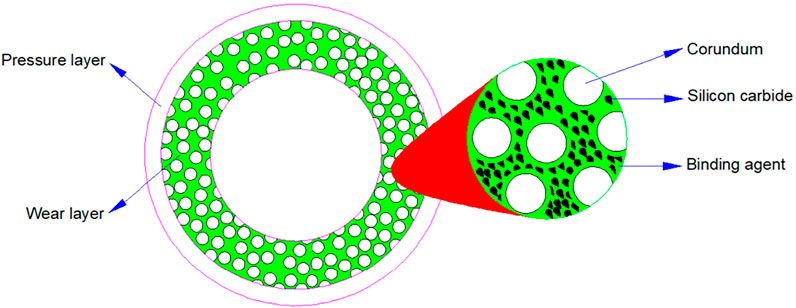
FIGURE 4. Internal structure diagram of composite pipe.
Engineering Application Verification
In order to quickly and clearly verify the wear of the pipeline, a certain iron ore concentrate transportation pipeline is selected for engineering verification. The iron ore originally uses traditional 16 Mn steel pipeline, which are severely worn and often need to be shut down for repairs. The pipeline need to be replaced every 6 months to a year, as shown in Figure 5.
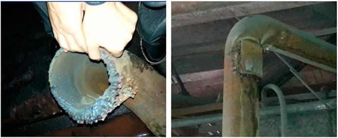
FIGURE 5. The traditional 16 Mn steel pipeline was worn out and repaired in less than a year.
Since August 2014, one of the delivery pipelines was replaced with a new composite wear-resistant pipeline, and the other delivery pipeline still uses 16 Mn steel pipelines for comparison, as shown in Figure 6. The new composite wear-resistant pipeline has been used until now, and there have been no problems such as pipeline wear through. Through the actual engineering application of the new wear-resistant pipeline, its wear resistance is verified, and the reliability of the pipeline wear resistance test method used in the study is also verified. It should be noted that the wear through of the traditional 16 Mn steel pipeline mainly occurs in the elbow part (Figure 5). In the application of this project, the elbow part of the new composite wear-resistant pipeline has not been worn through for more than 5 years. For mine filling, the severely worn parts of the pipeline also mainly occur in the elbow part. Therefore, the new wear-resistant pipeline has good engineering application value in the field of mine filling.
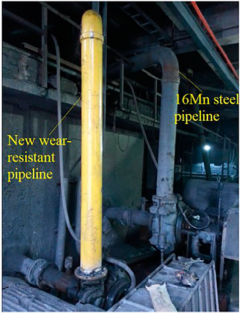
FIGURE 6. Engineering application of new wear-resistant pipeline.
Conclusion
1) In this paper, an experimental device and its application method for testing the wear resistance of the pipeline are proposed. The device can quickly and quantitatively obtain the wear resistance of the pipeline through the wear of the pipeline material, and then predict the service life of the pipeline.
2) This method is used to test the wear resistance of self-developed pipeline lining composite materials, traditional 16 Mn steel and ordinary carbon structural steel. The results show that the wear resistance of the new wear-resistant pipeline lining material is significantly better than that of 16 Mn steel and carbon structural steel. The internal reasons for the good wear resistance of the new lining material are analyzed from the two aspects of aggregate composition and structure.
3) Through a comparison engineering application of a certain iron ore concentrate transportation. The composite lined pipeline has been used for more than 5 years without any problems, while the traditional 16 Mn steel pipeline is worn through within 1 year. The practical application has verified the wear resistance of the composite lined pipeline and the reliability of the proposed test method. Especially, the good wear resistance in elbow part lays a good practical foundation for mine filling application.
Data Availability Statement
The original contributions presented in the study are included in the article/Supplementary Material, further inquiries can be directed to the corresponding author.
Author Contributions
YW: Investigation, Writing- original draft, Funding acquisition. G-fY: Investigation, Writing - original draft. C-lM: Conceptualization, Methodology, Supervision, Writing - review and editing. Q-lJ: Formal analysis, Writing - original draft. Q-gJ: Supervision, Funding acquisition. All authors read and approved the final manuscript.
Funding
This research was funded by the National Natural Science Foundation of China (No. 52042402), the Fundamental Research Funds for the Central Universities (No. FRF-IDRY-20-031).
Conflict of Interest
Author Q-gJ was employed by the company Zhengzhou Special Flux Materials Co., Ltd.
The remaining authors declare that the research was conducted in the absence of any commercial or financial relationships that could be construed as a potential conflict of interest.
Publisher’s Note
All claims expressed in this article are solely those of the authors and do not necessarily represent those of their affiliated organizations, or those of the publisher, the editors and the reviewers. Any product that may be evaluated in this article, or claim that may be made by its manufacturer, is not guaranteed or endorsed by the publisher.
References
Cao, X. Y., Deng, J., and Shang, G. C. H., (2014). Progress Made in Research on Cladding Process for Bimetal Clad Pipe. Steel Pipe 43 (02), 11–15.
Chandel, S. (2010). Studies on the Flow of High Concentration Coal Ash through Pipelines. PHD dissertation (New Delhi: Indian Institute of Technology Delhi).
Deng, D. W., Chen, R., and Zhang, H. C. (2013). Present Status and Development Tendency of Plasma Transferred Arc Welding. J. Mech. Eng. 49 (7), 106–112. doi:10.3901/jme.2013.07.106
Fu, Y. H., Wang, L. L., and Li, N. (2017). Research on Development and Technology of Wear-Resistant Pipeline for Filling in Mine. Nonferrous Met. Designs 44 (1), 1–4. doi:10.3969/j.issn.1004-2660.2017.01.001
Ghirian, A., and Fall, M. (2013). Coupled Thermo-Hydro-Mechanical-Chemical Behaviour of Cemented Paste Backfill in Column Experiments. Part I: Physical, Hydraulic and thermal Processes and Characteristics. Eng. Geology. 164, 195–207. doi:10.1016/j.enggeo.2013.01.015
Guo, J., and Zhang, B. X. (2015). Numerical Investigation of Impact Erosion in Liquid-Solid Two-phase Flow of the Backfilling Pipe. Sci. Tech. Rev. 33 (11), 49–53. doi:10.3981/j.issn.1000-7857.2015.11.008
Hewitt, D., Allard, S., and Radziszewski, P. (2009). Pipe Lining Abrasion Testing for Paste Backfill Operations. Minerals Eng. 22, 1088–1090. doi:10.1016/j.mineng.2009.03.010
Li, F. G., Wei, B., and Shao, X. D., (2011). Technical and Economic Analysis on Bimetal Pipeline. Corrosion Sci. Prot. Tech. 23 (01), 86–88.
Liu, Y. Y., Chen, Y. H., and Zhu, C. W. (2015). Analysis of Erosive Wear of Backfilling Transportation Pipeline. Lubrication Eng. 40 (07), 106–109. doi:10.3969/j.issn.0254-0150.2015.07.022
Mao, M. F., Wang, B. W., and Zhu, J. R. (2018). Study on Wear Mechanism of Gravity Transportation Pipeline for Backfilling Slurry[J]. Metal Mine 47 (04), 178–184. doi:10.19614/j.cnki.jsks.201804032
Rawat, A., Singh, S. N., and Seshadri, V. (2017). Erosion Wear Studies on High Concentration Fly Ash Slurries. Wear 378-379, 114–125. doi:10.1016/j.wear.2017.02.039
Shi, H. W., Huang, J. R., and Qiao, D. P. (2020). Study on the Abrasion of High Concentration Filling Slurry Self Flowing Pipeline in Deep Mine. Nonferrous Met. (Mining Section) 72 (04), 13–18. doi:10.3969/j.issn.1671-4172.2020.04.003
SimonLi, K-K., Humphrey Joseph, A. C., and Levy Alan, V. (1981). Erosive Wear of Ductile Metals by a Particle-Laden High Velocity Liquid Jet. Wear 73 (2), 295–309.
Tsai, W. J. A. I., Humphrey, J. A. C., Cornet, I., and Levy, A. V. (1981). Experimental Measurement of Accelerated Erosion in a Slurry Pot Tester. Wear 68 (3), 289–303.
Wang, H., Zeng, X. G., and Xiao, Y. G. (2016). Pipe Welding and SHS Ceramic Lined Preparation and Performance Test. Pipeline Tech. Equipment (1), 33–36. doi:10.3969/j.issn.1004-9614.2016.01.011
Wang, Y. F., Yuan, J. L., and Zhang, Y. F. (2013). Technology Status and Development Direction of Bimetal Pipe. Welded Pipe and Tube 36 (02), 5–9. doi:10.19291/j.cnki.1001-3938.2013.02.001
Wang, Y. F., Zhao, S. D., and Zhang, C. Y. (2015). Research Status and Development of Forming Technology for Bi-metal-lined Pipe China Metalforming Equipment Manufacturing Tech. 50 (03), 84–89. doi:10.16316/j.issn.1672-0121.2015.03.024
Wu, A. X., Wang, Y., and Wang, H. J. (2016). Status and Prospects of the Paste Backfill Technology. Metal Mine 45 (7), 1–9. doi:10.3969/j.issn.1001-1250.2016.07.001
Wu, A. X., Yang, Y., and Cheng, H. Y. (2018). Status and Prospects of Paste Technology in China. Chin. J. Eng. 40 (05), 517–525. doi:10.13374/j.issn2095-9389.2018.05.001
Wu, X. S., Wang, Y. P., and Tang, D. R. (2019). Influence of Solid Particle Concentration on Wear of Horizontal Pipeline. Education Modernization 6 (34), 200–201. doi:10.16541/j.cnki.2095-8420.2019.34.079
Xie, Y. s., (Jimmy)Jiang, J., and Tufa, K. Y. (2015). Wear Resistance of Materials Used for Slurry Transport. Wear 332-333, 1104–1110. doi:10.1016/j.wear.2015.01.005
Keywords: pipeline, wear resistance, quantitative test, mechanism, engineering application
Citation: Wang Y, Yang G-f, Ma C-l, Jia Q-l and Jin Q-g (2022) Quantitative Test and Engineering Application of Wear Resistance of a Kind of Mine-Filled Composite Pipeline. Front. Mater. 8:744944. doi: 10.3389/fmats.2021.744944
Received: 21 July 2021; Accepted: 22 October 2021;
Published: 05 January 2022.
Edited by:
Erol Yilmaz, Recep Tayyip Erdoğan University, TurkeyReviewed by:
Lijie Guo, Beijing General Research Institute of Mining and Metallurgy, ChinaLiang Cui, Lakehead University, Canada
Copyright © 2022 Wang, Yang, Ma, Jia and Jin. This is an open-access article distributed under the terms of the Creative Commons Attribution License (CC BY). The use, distribution or reproduction in other forums is permitted, provided the original author(s) and the copyright owner(s) are credited and that the original publication in this journal is cited, in accordance with accepted academic practice. No use, distribution or reproduction is permitted which does not comply with these terms.
*Correspondence: Qin-guo Jin, amlucWluZ3VvLnp6QDE2My5jb20=