 Kun Ye
 Zhicheng Tan1,2*
- 1School of Informatics, Xiamen University, Xiamen, China
- 2School of Aeronautics and Astronautics, Guilin University of Aerospace Technology, Guilin, China
- 3School of Electronic Science and Engineering (National Model Microelectronics College), Xiamen University, Xiamen, China
During underwater operations, divers must determine their own trajectories using the Inertial Navigation System (INS) they carry to improve operational efficiency. However, the INS contains a sensor bias that is also incorporated into the quadratic integration process to obtain the displacement, resulting in trajectory drift of the divers during prolonged self-guidance. To overcome the above problem, other aids are needed to correct the accumulated error of the INS. The single-beacon Assisted Inertial Navigation (AIN) method can improve the flexibility of inertial error correction while simplifying the localization equipment, which is suitable for the INS cumulative error correction scenario of divers. However, most of the traditional single-beacon assisted correction methods do not consider the effect of acoustic line bending on hydroacoustic ranging, and at the same time, they do not consider the problem of singular or pathological coefficient matrices introduced by inertial navigation neighbor localization deviations. Based on the above two shortcomings, this paper uses the acoustic velocity profile for acoustic line tracking, combines the localization idea of Mobile Primitives (MP), and proposes an MP-based acoustic line tracking-Assisted Inertial Navigation Localization (AINL) method, which constructs a sliding time window (STW) by taking the historical positioning of divers as a virtual primitive, and combines the nonlinear optimization method for iterative optimization search as a means to improve the accuracy and stability of self-navigation of the divers.
1 Introduction
Marine localization and navigation technology is widely used in many fields such as diving and salvage, resource exploration, and environmental monitoring [Luo et al. (2021); Zhang et al. (2021); Su et al. (2023); Zhang et al. (2024); Ye et al. (2023)]. Diving is the primary means by which humans explore, exploit and strategize the oceans [Brown and Wang (2013); Kaneko and Kubota (2021)]. The localization and navigation methods for divers mainly include the hydroacoustic localization method, which uses sound waves as information carriers, and the combined navigation method based on INS. Among them, INS is very suitable for diver navigation scenarios due to its good autonomy, continuity, stealth and real-time advantages in the navigation process (Lyu et al. (2022)). However, the drift deviation of the inertial sensor in INS causes the localization error of divers to accumulate over time, and it is difficult for a single INS to meet the application requirements of long-term underwater navigation Liu et al. (2021). Therefore, it is necessary to use other auxiliary methods to correct the accumulated error of the INS in time. Acoustic wave, as the only information carrier that can be transmitted over long distances underwater, has become an effective means to AIN for error correction [Cheng et al. (2022)].
Literature [Zhang et al. (2023)] designed two combined navigation schemes for Autonomous Underwater Vehicles (AUV) for different surface and underwater navigation requirements, respectively. Literature [Xu et al. (2022)] proposed a decentralized co-location method based on Adaptive Cubature Kalman Filter (ACKF) to improve the navigation accuracy of two lead AUVs. Literature [Zhang et al. (2022)] designed a Kalman Filter (KF) method based on a hybrid distribution model derived from acoustic signal round trip delay and pitch angle measurement models to reduce the effect of underwater carrier motion on navigation accuracy, but did not fundamentally eliminate the INS cumulative error. Literature [Ju-Cheng et al. (2017)] proposed an AUV navigation augmentation method based on single beacon ranging, which effectively suppresses the INS cumulative error by introducing distance, speed, and azimuth as measurement information. The single-beacon localization technique, which uses a single acoustic beacon to assist INS in self-navigation, not only simplifies the transponder deployment process of traditional hydroacoustic positioning systems, but also provides a high degree of localization flexibility with navigation accuracy similar to that of INS combined with traditional hydroacoustic localization systems [Hegrens et al. (2009)]. Literature [Jin et al. (2019)] combined acoustic localization and inertial navigation to propose a low-cost single beacon inertial navigation augmentation localization method, but it assumes a constant underwater acoustic velocity and does not consider the problem of acoustic line bending. Literature [Zhang et al. (2019)] proposed an AUV self-localization method based on Virtual Long Baseline (VLBL) and STW, but the method sets the ocean acoustic velocity to a fixed value without sound line correction, and the corresponding coefficient matrix is prone to singular or pathological situations, at which time it is difficult to directly solve the spatial localization of the AUV.
Therefore, this paper focuses on the basic array deployment problem of diver localization scenarios, adopts a single beacon on the water surface for Acoustic-Assisted Inertial Navigation Localization (AAINL), and combines the localization ideas of acoustic velocity field inversion and MP to reduce the deployment cost of the localization system while meeting the scenario requirements of high accuracy, near real-time and high flexibility of diver self-navigation. The localization method in this paper can effectively improve the accuracy, robustness and flexibility of localization estimation of the divers, which is of great practical value and significance for protecting the personal safety for divers and improving the efficiency of underwater operations.
2 Problem and methodologies
2.1 Inertial navigation and localization scenarios
Aiming at the problem of cumulative localization errors generated by divers in long-term inertial navigation scenarios, this paper proposes an AINL method based on acoustic line tracking of MP, and the localization scenario is shown in Figure 1A. Three adjacent locations P0, P1, P2, where the diver receives the acoustic signal from the surface beacon (SB) during the moving process, are selected as virtual primitives to construct the first STW, in which the adjacent displacements of the INS output and the slant distances obtained from the acoustic tracking are combined to solve the spatial localization of the diver at the nearest instant by the system of joint localization equations. The STW is updated and iterated as the diver moves until the corrected localization accuracy meets the requirements.
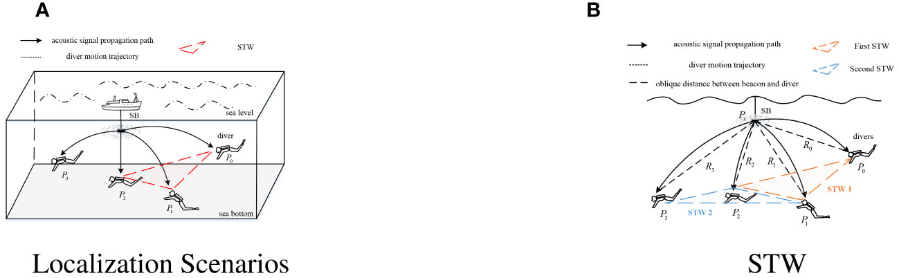
Figure 1 Localization scenarios for acoustic tracking inertial navigation methods based on MP. (A) Localization Scenarios; (B) STW.
Figure 1B shows the components of the first two STWs, where the orange dashed box represents the first STW constructed by P0, P1, and P2, and is denoted as STW 1. Assuming the initial localization is P0(x0,y0, z0), acoustic tracking is used to obtain the slant distance between the diver and the beacon as R0. After a period of time, the coordinates of divers are P1(x1,y1, z1), the relative displacement of P0 and P1 is recorded in the INS as ΔP10 = (Δx10, Δy10), and acoustic tracking is again used to obtain the slant distance R1. The third time the acoustic signal is received, the corresponding coordinate is set to P2(x2,y2, z2), and the displacements of P1 and P2, ΔP21 = (Δx21, Δy21), and the slant distance, R2, are recorded. The two-dimensional coordinates P0 and P1 (depth measured by the pressure transducer) are expressed as the difference between the coordinates to be solved, P2, and the relative displacement of the known INS in the form of Equation 1:
where and
Combined with the slant distance obtained by acoustic tracking, the system of joint nonlinear localization equations is:
In (2), the depth zi(i = 0,1,2) at each localization is measured by the pressure transducer, which can be considered a known quantity. The coordinate estimation problem for the diver P2 can be transformed into the problem of solving the corresponding system of localization equations in (2). Considering that the deviation of the adjacent localizations of the INS output may cause the problem of singular or pathological coefficient matrix, this paper adopts a nonlinear optimization method to iteratively search for the optimal solution of the localization of divers Wang et al. (2022).
2.2 Localization p process
Figure 2 shows the overall flow of the localization method in this paper, which includes a delay estimation module, a sound tracking module, an inertial navigation module, a nonlinear optimization module, and a STW iterative update module. The inverse sound velocity profiles are based on Array for Real-time Geostrophic Oceanography (Argo) data at 116.63-119.63E and 17.5-18.5N after Multi-Layer Perceptron (MLP) estimation of the first five orders of Principal Components (PC) estimation for better range.
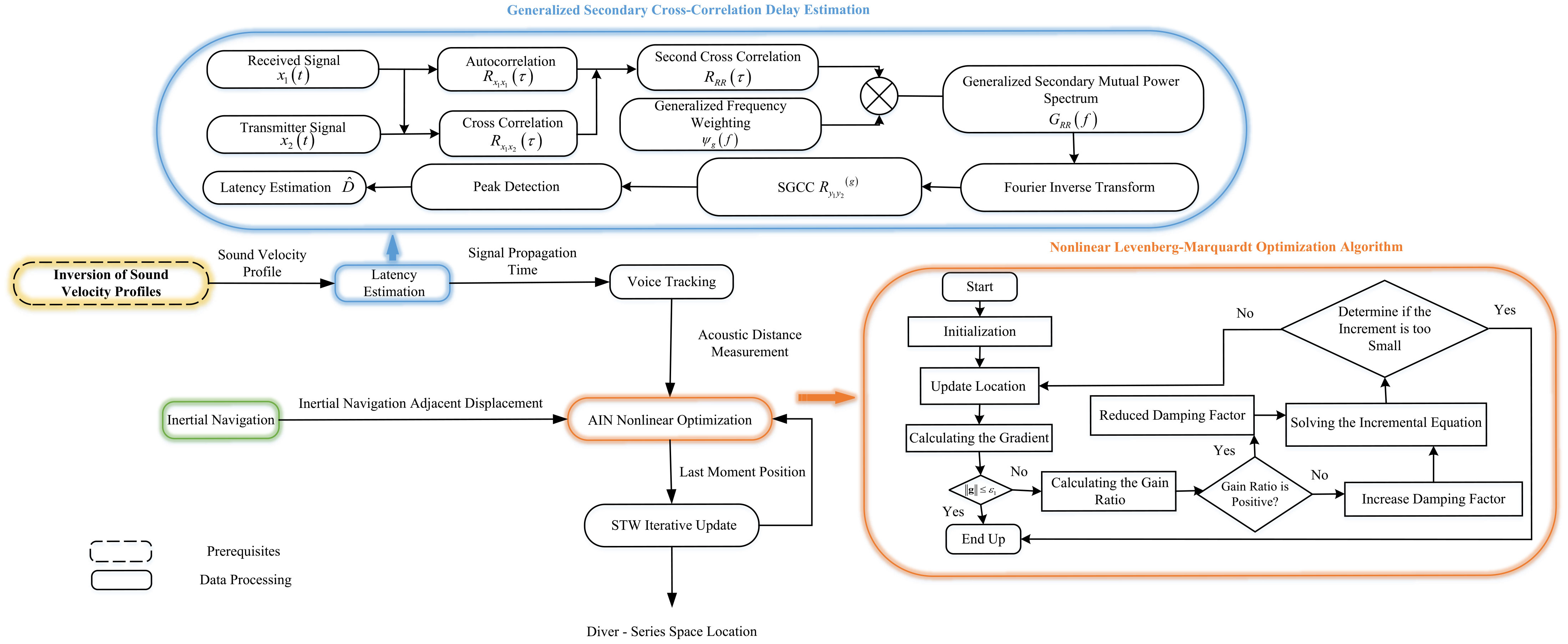
Figure 2 The general flowchart of the localization method in this paper.
The INS solution of the Inertial Navigation Module requires the following four steps in sequence: attitude update, coordinate transformation, velocity update, and localization update.
The acoustic line tracking module, as a crucial component of the inertial navigation-based error correction, aims to obtain the acoustic distance measurement information between the diver and the SB, thus providing the slant distance required for the nonlinear optimization process. The acoustic tracking module is first provided with the time of arrival (TOA) of the beacon acoustic signal by the time delay estimation module. Then, an iterative dichotomous search is performed to correct the acoustic line curvature based on the initial grazing angle of the acoustic line. Considering the shallow sea environment where divers operate, the acoustic signal is easily disturbed by multipath channels and environmental noise during propagation, so the TOA method should be selected with both multipath and noise resistance. In this paper, Second Generalized Cross Correlation (SGCC) is selected as the localization method to estimate the TOA of the received signal from the diver in order to avoid pseudo peaks in the cross correlation Yang et al. (2010). The method steps are as follows:
First, the autocorrelation operation is performed on x1(t) to obtain the autocorrelation function Rx1x1(τ). Second, the mutual correlation function Rx1x2(τ) of x1(t) and x2(t) is calculated, followed by the calculation of the mutual power spectral function GRR(f) of Rx1x1 and Rx1x2. Then, the frequency domain filtering of GRR(f) is performed in conjunction with the generalized frequency weighting function ψg(f). Finally, the filtered secondary mutual power spectrum is subjected to Fourier Inverse Transform to obtain the Second Generalized Cross Correlation function , as shown in Equation 3:
Since the method in this paper corresponds to the active localization scenario, when the power of the acoustic signals emitted by SB is large, the function normalizes the amplitude of the reciprocal power spectrum in the frequency domain, and is able to effectively sharpen the correlation peaks in active localization scenarios with large signal power, and is suitable for underwater acoustic environments with low or moderate reverberation, and the expression for the phase transformation (PHAT) weighting function is given by .
When searching for peaks for (3), the time corresponding to the peaks is the time delay for the diver to receive the signal as , as shown in Equation 4:
The SGCC-PHAT method in the attempted study combines both good noise immunity and multipath immunity, and is more suitable than other algorithms for delay estimation scenarios of diver-received signals in the noisy environment of the shallow sea.
The nonlinear optimization module is mentioned in the next section.
2.3 Nonlinear optimization
The system of localization Equation (2) is transformed into the following form if the depth of divers, the coordinates of the single beacon on the water surface and the acoustic distance measurements R1, R2, R3 are known:
where is the coordinate change of INS outputs and in the inertial reference system.
If the coordinate to be solved is set to , the Equation (5) is expressed in the form of the following error vector:
Squaring the Equation (6) yields the objective function as follows:
The sum of squares of the minimized range error terms according to Equation (5–7), and then use the iterative method to nonlinearly optimize the above least squares problem. The localization method in this paper uses the Levenberg-Marquardt (LM) method for nonlinear optimization of the spatial localization of divers in the following way:
First, the coordinates to be solved are set as a vector x(x,y). The error term e(x) is linearized based on a first order Taylor series expansion with the expression in Equation 8:
where J(x) is the Jacobi matrix of e(x) with respect to x and Δx is the iteration step.
The minimization objective function is then approximated as a linear least squares problem to solve for the increment, as shown in Equation 9:
The LM method introduces a damping coefficient µ in the construction of the incremental equation, which can be expressed as Equation 10:
where I is the unit array; the initial value of the damping coefficient, µ0 = τ × max{aii}, where A0 = J(x0)TJ(x0), aii is the diagonal elements of A0; and τ is a constant, usually set to 10−3 or 1.
The quality of each iteration step is evaluated according to the change in the goodness of approximation , which defines the gain ratio , as shown in Equation 11:
The denominator represents the degree of decrease of the first-order differential component in each iteration, and the numerator represents the decrease of the actual function. When ρ is small, it means that the approximation degree of the iteration step is poor, and µ should be increased accordingly; on the contrary, when ρ is large, µ should be decreased. In this paper, the localization method adopts the µ updating strategy as follows: when ; otherwise, µ = µ × ν ν = 2 × ν, the initial value ν0 = 2. After adjusting the damping coefficient, it is first substituted into the increment equation to compute the increment amount, and then the increment amount is iterated to update the localization, and then a new round of iteration is started, and the iteration is stopped only when the increment amount is sufficiently small or the gradient of the descent is sufficiently small.
3 Simulation results and analysis
3.1 Simulation analysis of delay estimation module
To investigate the estimation performance of the SGCC-PHAT method in the delay estimation module in shallow sea localization scenarios, this subsection compares the delay estimation effects of different cross-correlation algorithms in terms of noise resistance and multipath resistance, respectively. Assuming that the receiver and transmitter have completed time synchronization, the anti-noise performance of the method is analyzed by adding Gaussian white noise of different power to the transmit signal; and the multipath resistance of the method is explored by simulating the shallow sea multipath channel using the BELLHOP channel model.
First, the noise immunity performance of the four cross-correlation algorithms is analyzed. In this simulation, a single-frequency sine wave with a frequency of 1000 Hz is used as the transmit signal in this 167 simulation. The signal is sampled at 50 kHz, with 1024 samples and a real-time delay value of 100 sample intervals (i.e., 2 ms). The simulation analyzes the noise immunity of the four cross-correlation algorithms from the two scenarios of high signal-to-noise ratio (SNR) (20 dB) and low SNR (-20 dB).
Figure 3 shows the delay estimation results of the Cross Correlation (CC) algorithm, the Generalized Cross Correlation-PHAT (GCC-PHAT) algorithm, the Second Cross Correlation (SCC) algorithm, and the SGCC-PHAT method at high SNR. Overall, all four algorithms can accurately estimate the true delay value of the received signal below 20 dB. From the horizontal comparison, it can be observed that when the signal power is greater than the noise power, the GCC-PHAT method has sharper correlation peaks compared to the CC algorithm, the peak spreading of the CC method leads to a reduction in the resolution of the peaks, and the SGCC-PHAT method and the SCC method have a similar pattern. From the longitudinal comparison, it can be observed that the amplitude of the interference noise around the peaks is significantly reduced in the SGCC-PHAT method compared with the GCC-PHAT algorithm, thus verifying that the two cross-correlation operations can sharpen the peaks and further inhibit the noise from interfering with the signal. The above simulation verifies the good resolution of the SGCC-PHAT method for delay estimation under high SNR conditions, as well as a certain resistance to side flap interference.
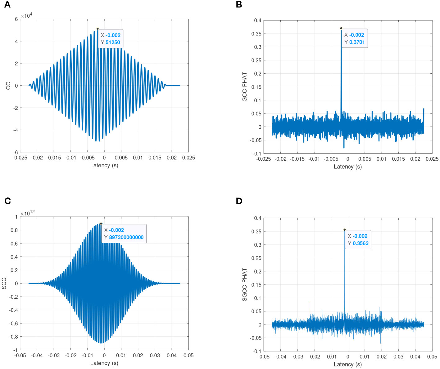
Figure 3 Estimation performance comparison of four cross-correlation algorithms under high SNR conditions (20 dB). (A) CC; (B) GCC-PHAT; (C) SCC; (D) SGCC-PHAT.
Figure 4 compares the estimation performance of the four types of cross-correlation algorithms under low SNR conditions. Among the four algorithms, only CC and SCC estimate accurately, the true value of delay of GCC-PHAT is overwhelmed by a large amount of noise, and the estimate of SGCC-PHAT method contains a small amount of bias (0.00012 s). From the side-by-side comparison, it can be seen that CC has better noise immunity compared to GCC-PHAT, and the true delay value can still be estimated under low SNR conditions. The estimation accuracy of GCC-PHAT decreases sharply with the increase of noise power under the low SNR conditions. This phenomenon occurs because the PHAT weighting function in GCC-PHAT relies on phase delay estimation. When the signal is flooded with noise, the phase of the noise occupies the main component in the estimation result, so the estimation error increases sharply. Compared with GCC, CC has better noise immunity because it preserves the amplitude information in the frequency domain. From the longitudinal comparison, although the estimation accuracy of SGCC-PHAT decreases accordingly under the low SNR condition, its estimation error is generally very small (0.00012 s) compared to GCC-PHAT, which confirms that SGCC-PHAT has better noise suppression ability compared to GCC-PHAT. From the above simulation analysis of the anti-noise performance, it can be seen that under the high SNR condition, the SGCC has a sharper correlation peak compared with the SCC and is more sensitive to the estimation error; under the low SNR condition, the SGCC-PHAT benefits from the two cross-correlation operations to inhibit the interference of the noise on the signal better than the GCC-PHAT, and it has a higher robustness. Considering that the water SB in the localization scenario of this chapter is actively transmitting acoustic signals as a sound source, there is no low SNR environmental condition, in which case it is feasible and superior to choose the SGCC-PHAT as the delay estimation method for localization in this chapter.
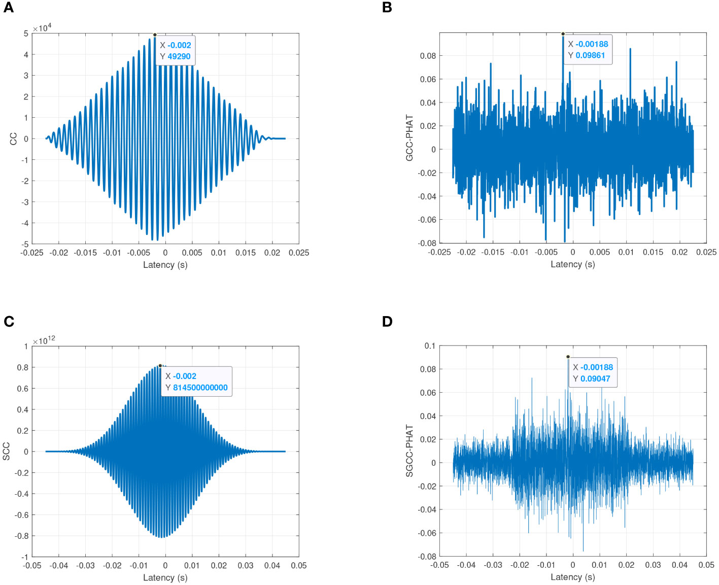
Figure 4 Estimation performance comparison of four cross-correlation algorithms under low SNR conditions (-20 dB). (A) CC; (B) GCC-PHAT; (C) SCC; (D) SGCC-PHAT.
Second, simulation analysis is performed to analyze the anti-multipath performance of the four types of cross-correlation algorithms. In this simulation, the BELLHOP model is selected to simulate the underwater multipath channel, and the received acoustic signal is obtained by calculating the convolution of the transmitted signal and the channel impulse response, and the different cross-correlation algorithms are applied to the received signal for time delay estimation. It should be noted that the sound velocity profile used in the BELLHOP model is the inverted sound velocity profile of August 2017 in the China South Sea, and the rest of the parameter settings are shown in Table 1. Considering the complexity of the underwater environment, in this simulation, the linear frequency modulation (LFM) signal is selected as the transmission signal, the center frequency of the signal is set to 30 kHz, the bandwidth is 5 kHz, the duration is 20 ms, and the real propagation time of the acoustic signal can be obtained from the model calculation as 0. 65645 s. The LFM signal before and after passing through the BELLHOP channel is shown in Figure 5, and the change of the waveform shows that the received signal is not only delayed in time, but also the multipath effect leads to different degrees of attenuation of the signal amplitude. Based on the received signals shown in Figure 5, the antimultipath performance of the four types of cross-correlation algorithms is compared, and a total of thirty simulations are performed, which shows that the SGCC-PHAT has a better antimultipath capability, and only one simulation result is shown as shown in Figure 6. The figure reflects the ability of different cross-correlation algorithms to resist the multipath effect in the shallow sea, from which it can be seen that the GCC-PHAT and the SGCC-PHAT have better anti-polymath performance compared to the other two algorithms, and the delay estimation error of both of them is only 0. This verifies that the SGCC-PHAT can resist the multipath effect in the shallow sea, and the estimation error of CC and SCC is extended to 0.00001s. This verifies that SGCC-PHAT can resist the multipath effect in the shallow sea, and SCC is more effective in the shallow sea. SGCC-PHAT can extract the propagation delay of the direct signal in the multipath channel better than CC and SGCC, and is more suitable for the localization scenarios the shallow sea operation of divers.
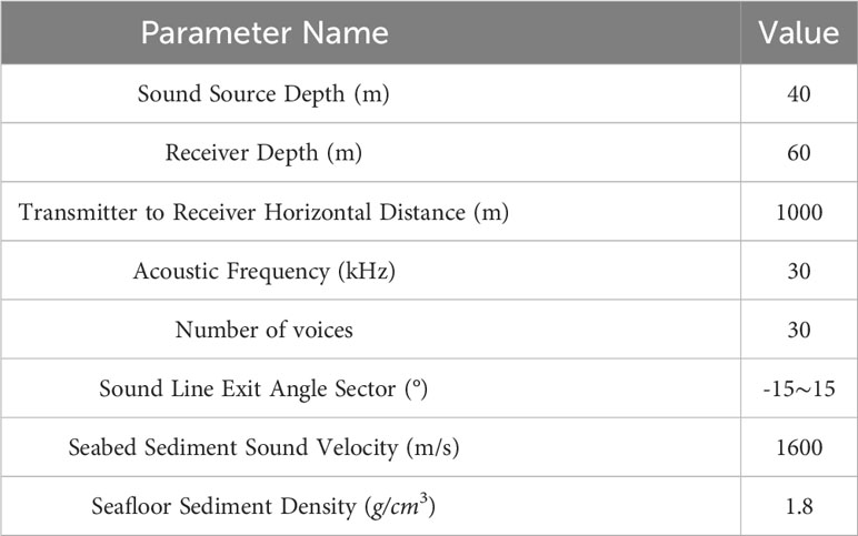
Table 1 BELLHOP model parameterization.
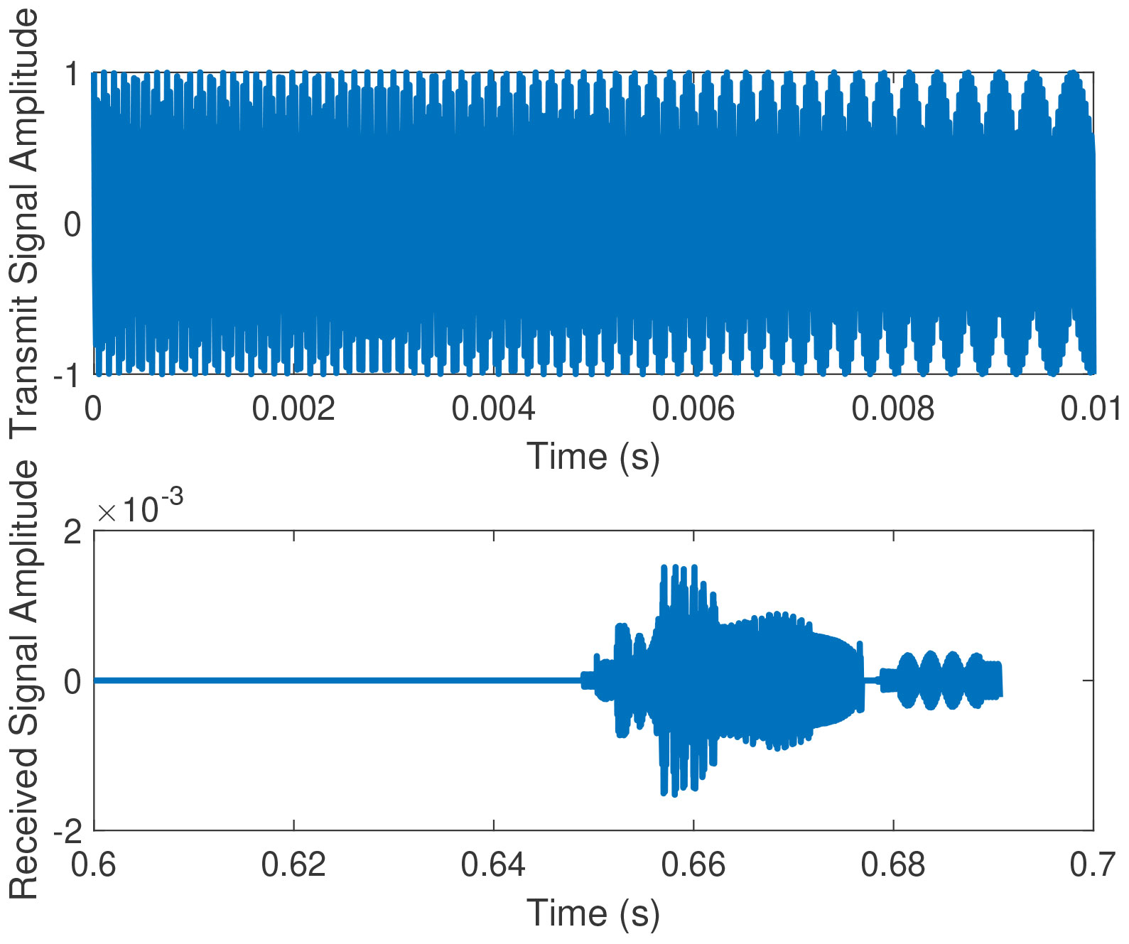
Figure 5 Comparison of signal waveforms before and after passing through the BELLHOP channel.
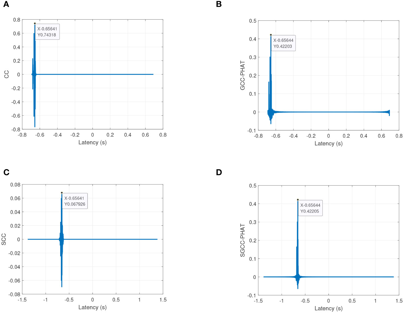
Figure 6 Estimation performance comparison of four cross-correlation algorithms under BELLHOP multi-traffic channels. (A) CC; (B) GCC-PHAT; (C) SCC; (D) SGCC-PHAT.
In summary, this subsection verifies, based on simulation, that the SGCC-PHAT has both good anti-noise performance and anti-multipath performance, and is more suitable than other algorithms for the delay estimation scenarios of the received signals of divers in the noise environment of the shallow sea, and thus the methodology in this chapter selects the SGCC-PHAT as a delay estimation method for the voice tracking module with feasibility and superiority.
3.2 Nonlinear module simulation and analysis
This subsection demonstrates the INS cumulative error correction results of the proposed method, and also explores the effect of the transmission period of SB on the INS cumulative error correction. Based on the received signal delay estimation using the SGCC-PHAT algorithm, the INS cumulative error correction performance of the proposed method is simulated and analyzed.
The Inertial Measurement Unit sensor error settings in the simulation are the same as in Table 2, and the measurement period is set to 0.1 seconds. The diver is moving at a speed of approximately 1 knot. The SB is placed at a depth of 0.5 m underwater, and the corresponding latitude and longitude are 17.5016N and 116.6016E. In this simulation, the East-North-Up (ENU) coordinate system is used as the reference coordinate system for navigation, and the initial localizations of divers of 17.5N and 116.6E are used as the origin of the reference system, and the relative localizations of the moving trajectory of divers and the SB are shown in Figure 7. The simulation uses Root Mean Square Error (RMSE) to measure localization accuracy.
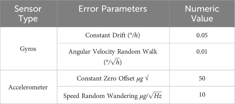
Table 2 Inertial Measurement Unit (IMU) sensor error parameter settings.
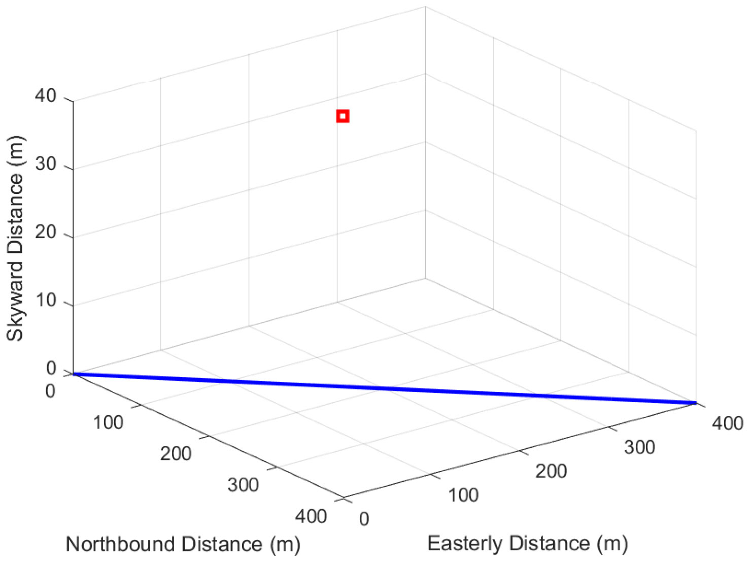
Figure 7 Diver motion trajectory and SB localization.
Table 3 shows the localization errors for different STWs for a beacon transmission period of 20 seconds, and from the analysis of the graphs, it can be seen that the localization errors of the four STWs are less than 5 meters, and the corresponding localization errors of the second and third STWs are reduced to about 1 meter, which improves the accuracy of INS localization by about 98% compared with the INS localization accuracy, and the percentage of localization error is less than 0.5%, and the high-precision correction of the cumulative INS error is achieved in a minimum of only three STWs.
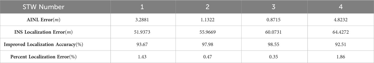
Table 3 Comparison of localization errors for a 20-second beacon duration.
Next, the number of STWs is selected as four, and the total simulation time is set to 1000 seconds, of which the first 420 seconds is for Purely Inertial Navigation (PIN), and the AAINL is performed in 420-520 seconds, thus simulating the actual operation scenario in which the diver moves for a certain period of time and then performs error correction. Figure 8 shows the localization trajectory and error of this method when the transmission period of the SB is 20 seconds, 40 seconds, 60 seconds and 80 seconds. The black line in the figure indicates the ideal motion trajectory of divers during 420 seconds to 520 seconds, the blue line indicates the motion trajectory of divers output by the INS, and the red line corresponds to the motion trajectory of divers after AINL by the method of this paper. The depth of divers is measured by the pressure sensor with negligible numerical error.
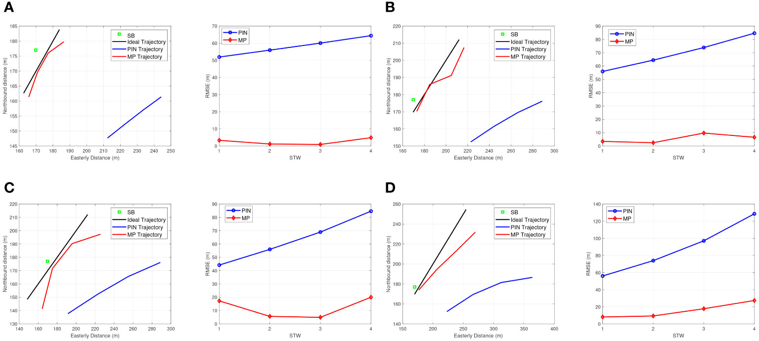
Figure 8 Diver trajectories and localization errors under different beacon transmission cycles. (A) Beacon transmission time of 20 seconds; (B) Beacon transmission time of 40 seconds; (C) Beacon transmission time of 60 seconds; (D) Beacon transmission time of 80 seconds.
From Figure 8, it can be observed that the cumulative INS error causes the localization of divers solved by PIN to deviate seriously from the true value, and the acoustic-assisted correction using SB in method of this papers can estimate the localization of divers closer to the true coordinates. The reason why the MP trajectory in Figure 8 is close to the ideal trajectory at the beginning and then gradually moves away from it is that in the iteration of the STW, the accuracy of the localization of divers first gradually improves with the introduction of acoustic ranging, and then, due to the increase in the distance between the diver and the SB, the accuracy of acoustic ranging at this time decreases, leading to the increase in the localization error corresponding to the fourth STW.
From the left vertical comparison of each figure in Figure 8, it can be seen that although the moving trajectories vary under different acoustic distance measurement cycles, they are generally closer to the real value than the trajectories output by the INS, and the above phenomenon is attributed to the fact that method of this papers uses acoustic ranging to introduce the auxiliary information of distance constraints.
Further observation shows that when the diver is closer to the SB, the accuracy of this method is higher, indicating that the distance between the SB and the diver is a key factor affecting the performance of acoustic assisted localization, and the beacon should be deployed as close as possible to the moving trajectory of divers. The localization errors under different acoustic measurement cycles are shown in the right vertical comparison of each figure in Figure 8, from which it can be seen that the localization error of method of this papers is significantly smaller than the INS localization error. As the cumulative error of the INS increases, the localization error of the MP also increases. When the beacon transmission period is 40 seconds, the localization errors of the four STWs are less than 10 meters; when the beacon transmission period is 60 seconds, the maximum localization error corresponding to the STWs is close to 20 meters; when the beacon transmission period further increases to 80 seconds, the maximum error corresponding to the STWs has exceeded 20 meters. The reason for the above increase in the localization error of the MP is that the size of the SB transmission period essentially reflects the distance between adjacent localizations in the STW, i.e., the length of the baseline between the MP. Increasing the beacon transmission period leads to a larger distance between neighboring localizations in the STW, at which time the INS cumulative error also increases, and substituting the relative displacement with a larger deviation into the set of nonlinear localization equations increases the auxiliary localization error. The method in this paper has the problem of choosing the beacon transmission period, because the INS neighbor displacement is introduced as a known quantity, and the localization accuracy improvement is limited by the INS cumulative error.
The localization accuracy improvement values for the four transmission cycles compared with INS in Figure 8 are shown in Table 4, from which it can be seen that as the beacon transmission cycle increases, the localization accuracy improvement of method of this papers as a whole shows a decreasing trend, which is related to the increase of the INS neighborhood localization deviation. It should be noted that the localization accuracy of the method in this paper is also related to the distance of the diver from the SB, so the larger value of the localization accuracy improvement under each transmission period in the table tends to correspond to the STW closest to the beacons. According to the simulation verification, the localization method in this paper has a certain degree of error correction effect in transmission cycles less than 200 seconds.
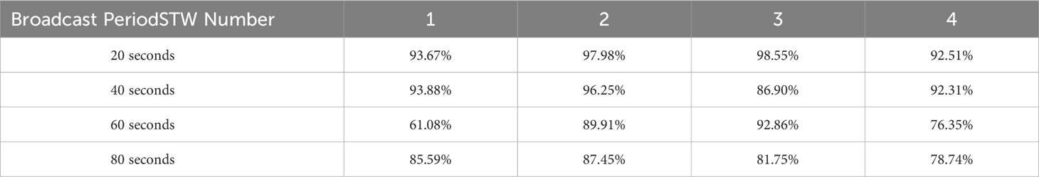
Table 4 Improving the localization accuracy of the method of this paper over INS with different beacon transmission periods.
From the above simulation analysis, it can be seen that the localization method in this paper can effectively correct the cumulative error of INS under different beacon broadcasting cycles, and the effect of improving the localization accuracy is very significant. The factors affecting the estimation accuracy of the localization method in this paper are mainly the broadcasting period of the SB and the proximity of the diver to the SB. In this paper, the 20-second transmission period is chosen as the acoustic distance measurement period for the AINL, and the SB is placed as close as possible to the trajectory of divers to realize the fast and high-precision INS error correction. Considering that divers need to quickly correct the accumulated INS error during underwater operation, designing too many MP will cause more serious localization deviation and thus reduce the localization accuracy, so this paper chooses three MP to construct a STW In the process of localization, three to four STWs can quickly eliminate the accumulated INS error, and choosing too many STWs not only increases the computational complexity, but also is prone to the interference of acoustic ranging distance and affects the correction effect.
4 Conclusion
In this paper, an acoustic tracking AINL method based on MP is proposed. Considering that it is difficult to lay a large number of acoustic base arrays in a short time for the sudden operation scenarios of divers, acoustic tracking assisted localization using a single beacon on the water surface combined with acoustic line tracking combines the flexibility and simplicity of single beacon localization and improves the aquatic acoustic localization accuracy of divers. The localization idea of MP is introduced, and a STW consisting of three virtual primitives is constructed using the current localization of divers and two historical positions, and the spatial localization of divers at the nearest moment is solved based on the acoustic distance measurement and the inertial navigation displacement in the neighboring measurement period. To solve the problem of singularity or pathology in the coefficient matrix of the localization equation system due to the deviation of the neighboring localizations of the inertial guides, the LM method is used for nonlinear iterative optimization search. Then, how to realize the time synchronization between the SB and the diver is investigated and the corresponding underwater experiments are carried out.
Data availability statement
The original contributions presented in the study are included in the article/supplementary material. Further inquiries can be directed to the corresponding author.
Author contributions
KY: Conceptualization, Project administration, Visualization, Writing – original draft. ZT: Supervision, Writing – review & editing. WW: Supervision, Writing – review & editing. TT: Conceptualization, Supervision, Writing – review & editing, Writing – original draft. LZ: Supervision, Writing – review & editing. YW: Writing – review & editing.
Funding
The author(s) declare that financial support was received for the research, authorship, and/or publication of this article. This work was supported by the Key Research and Development Program of Guangxi, grant number AB21196066, in part by the Key Research and Development Program of Guilin, grant number 20220113-6, in part by Key Research and Development Program of Guilin, grant number 20210206-3, and in part by the Guangxi Science and Technology Plan Project (Grant No.AD22035141).
Conflict of interest
The authors declare that the research was conducted in the absence of any commercial or financial relationships that could be construed as a potential conflict of interest.
Publisher’s note
All claims expressed in this article are solely those of the authors and do not necessarily represent those of their affiliated organizations, or those of the publisher, the editors and the reviewers. Any product that may be evaluated in this article, or claim that may be made by its manufacturer, is not guaranteed or endorsed by the publisher.
References
Brown H. C., Wang H. (2013). Underwater augmented reality: Navigation and identification. 2013 OCEANS - San Diego. 1–5.
Cheng S., Cheng J., Zang N., Cai J. (2022). “Polar sins/usbl integrated navigation algorithm considering acoustic communication delays,” in 2022 5th International Symposium on Autonomous Systems (ISAS). 1–6.
Hegrens, Gade K., Hagen O. K., Hagen P. E. (2009). “nderwater transponder positioning and navigation of autonomous underwater vehicles,” in OCEANS 2009. 1–7.
Jin B., Xu X., Zhu Y., Zhang T., Fei Q. (2019). Single-source aided semi-autonomous passive location for correcting the position of an underwater vehicle. IEEE Sensors J. 19, 3267–3275. doi: 10.1109/JSEN.7361
Ju-Cheng Z., Chun-Hao S., Da-Jun S., Yun-Feng H. (2017). “Auv integrated navigation algorithm based on single beacon ranging,” in 2017 IEEE International Conference on Signal Processing, Communications and Computing (ICSPCC). 1–5.
Kaneko K., Kubota N. (2021). “Underwater acoustic positioning system using ultrasonic waves for diving support,” in 2021 World Automation Congress (WAC). 308–312.
Liu S., Zhang T., Zhang J., Zhu Y. (2021). A new coupled method of sins/dvl integrated navigation based on improved dual adaptive factors. IEEE Trans. Instrumentation Measurement 70, 1–11. doi: 10.1109/TIM.2021.3118090
Luo J., Yang Y., Wang Z., Chen Y. (2021). Localization algorithm for underwater sensor network: A review. IEEE Internet Things J. 8, 13126–13144. doi: 10.1109/JIOT.2021.3081918
Lyu X., Hu B., Wang Z., Gao D., Li K., Chang L. (2022). A sins/gnss/vdm integrated navigation fault-tolerant mechanism based on adaptive information sharing factor. IEEE Trans. Instrumentation Measurement 71, 1–13. doi: 10.1109/TIM.2022.3214628
Su R., Gong Z., Li C., Shen X. (2023). Algorithm design and performance analysis of target localization using mobile underwater acoustic array networks. IEEE Trans. Vehicular Technol. 72, 2395–2406. doi: 10.1109/TVT.2022.3211830
Wang S., Xu M., Zhang X., Wang Y. (2022). Fitting nonlinear equations with the levenbergmarquardt method on google earth engine. Remote Sens. 14, 2055. doi: 10.3390/rs14092055
Xu B., Hu J., Guo Y. (2022). An acoustic ranging measurement aided sins/dvl integrated navigation algorithm based on multivehicle cooperative correction. IEEE Trans. Instrumentation Measurement 71, 1–15.
Yang Z., Xu W., Xiao Z., Pan X. (2010). “Passive localization of an autonomous underwater vehicle with periodic sonar signaling,” in OCEANS’10 IEEE SYDNEY. 1–4.
Ye K., Cai Y., Hong S., Sun H. (2023). Direction-of-arrival estimation based on difference-sum co-array of a special coprime array. Electron. Lett. 59, e12701. doi: 10.1049/ell2.12701
Zhang T., Wang Z., Li Y., Tong J. (2019). A passive acoustic positioning algorithm based on virtual long baseline matrix window. J. Navigation 72, 193206. doi: 10.1017/S0373463318000590
Zhang X., He B., Gao S. (2023). An integrated navigation method for small-sized auv in shallow-sea applications. IEEE Trans. Vehicular Technol. 72, 2878–2890. doi: 10.1109/TVT.2022.3216003
Zhang X., Wu H., Sun H., Ying W. (2021). Multireceiver sas imagery based on monostatic conversion. IEEE J. Selected Topics Appl. Earth Observations Remote Sens. 14, 10835–10853. doi: 10.1109/JSTARS.2021.3121405
Zhang X., Yang P., Wang Y., Shen W., Yang J., Wang J., et al. (2024). A novel multireceiver sas rd processor. IEEE Trans. Geosci. Remote Sens. 1–1. doi: 10.1109/TGRS.2024.3362886
Keywords: underwater active localization, assisted inertial navigation localization, sound source localization, sound velocity profiling, mobile primitives
Citation: Ye K, Tan Z, Wang W, Tian T, Zhou L and Wang Y (2024) A mobile prototype-based localization approach using inertial navigation and acoustic tracking for underwater. Front. Mar. Sci. 11:1368317. doi: 10.3389/fmars.2024.1368317
Received: 10 January 2024; Accepted: 15 February 2024;
Published: 22 March 2024.
Edited by:
Xuebo Zhang, Northwest Normal University, ChinaCopyright © 2024 Ye, Tan, Wang, Tian, Zhou and Wang. This is an open-access article distributed under the terms of the Creative Commons Attribution License (CC BY). The use, distribution or reproduction in other forums is permitted, provided the original author(s) and the copyright owner(s) are credited and that the original publication in this journal is cited, in accordance with accepted academic practice. No use, distribution or reproduction is permitted which does not comply with these terms.
*Correspondence: Zhicheng Tan, dGFuemNAZ3VhdC5lZHUuY24=