 Yanhui Wang
 Cheng Wang1
 Ming Yang
 Shaoqiong Yang
- 1Key Laboratory of Mechanism Theory and Equipment Design of Ministry of Education, School of Mechanical Engineering, Tianjin University, Tianjin, China
- 2The Joint Laboratory of Ocean Observing and Detection, Pilot National Laboratory for Marine Science and Technology (Qingdao), Qingdao, Shandong, China
Underwater glider (UG) is one of the most promising autonomous observation platforms for long-term ocean observation, which can glide through seawater columns by adjusting its buoyancy and attitude. Hydrodynamic shape, especially the wing parameters, has an important influence on the glide performance of UG. In this paper, a sweep wing strategy inspired by the swift wings is proposed to apply pre-adjustable sweep wings for UGs, so as to improve the glide performance in different glide conditions. The approximate model that describes the relationship between the hydrodynamic coefficients of UG and the wing sweep angles is established with computational fluid dynamics method. By importing the approximate models into the dynamic model, the glide performance analysis, including endurance ability and trajectory accuracy, is performed to analyze the effect of the various sweep wings. The analysis results indicate that different sweep angles of wings are required by UG to obtain the optimal ability in gliding range, gliding duration, turn and resisting current, and the sweep wing strategy is useful for UG to improve its performance in observation mission due to the uncertainty of ocean environment.
Introduction
Animals have been the bio-inspirational source for some novel concepts of locomotion (Triantafyllou and Triantafyllou, 1995), sensing (Yang et al., 2010; Miller, 2018) and the intelligent control (Low and Willy, 2006) of underwater vehicles, which have the adaptability to changes in the environment and the ability for self-repair of the system. Thus, bionic underwater robots have become one of the focuses of robotics in recent years because of their high flexibility and intelligence (Zeng et al., 2006). However, there may exist a certain difference between the human-made systems and the biological systems in design space.
Instead of proving general benefits of biological systems, this paper aims to investigate the usefulness of the wings with various sweep angles (various sweep wings for short) based on bio-inspired for underwater gliders (UGs). In fact, nature’s flyers have been excellent inspirations of various air vehicles. A lot of efforts have been made to mimic bio-flight mechanisms in order to achieve similar aerodynamic performances, such as lift and thrust enhancement and high stability with minimal power consumption (Rojratsirikul, 2013).
The morphing wings generally have a variable shape or structure. According to their morphing strategies and objectives, morphing wings are classified into different categories, mainly involving variable camber (Pendleton et al., 2000), variable thickness (Popov et al., 2010), twist morphing (Raither et al., 2013), span morphing (Vale et al., 2011), variable sweep (Powers et al., 1992) and folding wing (Wang and Dowell, 2011). From smaller air vehicles to larger unmanned aerial vehicles and human-powered hang gliders, many attempts have been made to improve the vehicle performance using concepts found in nature. The concept of variable sweep wing was adopted for military fighter aircraft from the 1950s, primarily to achieve higher supersonic cruising speeds (Li et al., 2018). Kilgore (1971) measured aerodynamic damping and oscillatory stability in pitch and in yaw and the effective-dihedral parameter for two configurations of a model of a variable-sweep-wing multimission military airplane by using a small-amplitude forced-oscillation mechanism. Bulekov and Teryev (1972) investigated the dynamics of variable sweep wings aircraft in the course of changing geometry. Dobbs et al. (1985) tested the two dynamically scaled 0.1 scale composite semispan variable sweep wing models. Gursul et al. (2006) investigated spectral features of separated flows over various low-sweep wings, their relation to the observed optimum frequencies, and the effect of wing sweep angle.
The influence of bird wings on artificial vehicles was firstly reflected in Leonardo da Vinci’s studies of a fluid and aerodynamic forces over a bird wing (Videler, 2006), based on which Otto Lilienthal built a large glider and flew it successfully (Jones and Platzer, 2009). A great number of flapping-wing micro air vehicles (Krashanitsa et al., 2009) have been designed and developed inspired by the flapping flights of birds. Besides flapping, bird wings can also sweep back, as can be seen on a swift (Lentink et al., 2007), based on which (Summers and Mahannah, 2008) studied what airplane designers could learn from the shape-changing wings of birds. In addition, flight mechanism of insects has greatly motivated air vehicle designers, especially when the size of the vehicle is the main concern. Ellington (1999) presented the detailed aerodynamic characteristics of an insect-based flying machine in an attempt to provide a design for flapping wing micro air vehicles. Van Breugel et al. (2008) designed a flapping hovering micro air vehicle taking advantage of the clap and fling mechanisms of insects, which considered four pairs of wings. Wood (2008) designed an insect-sized micro air vehicle inspired by dipteran insects capable of vertical liftoff with external control and power. The research team at Harvard Microrobotics Laboratory developed another insect-sized flapping wing micro air vehicle inspired by the biology of a bee and the insect’s hive behavior (Wood et al., 2012). Tanaka et al. (2011) investigated the effect of wing flexibility on lift generation using an at-scale model to develop an artificial hoverfly wing.
As a kind of ocean observation platform, UG is widely applied in oceanographic sensing and data collection, due to its advantages of low cost and long gliding range (Rudnick et al., 2004; Rudnick, 2016; Sánchez et al., 2020; Petritoli et al., 2021). UG can dive or climb in the seawater column by adjusting its buoyancy, and the horizontal motion can be realized with the lift generated by its wings (Yang et al., 2022). The hydrodynamic shape, especially the wing shape, has a major impact on the glide performance of UG. The investigations in recent years have provided numerous results related to the wing shape design.
Lyu et al. (2019) investigated the impact of winglet on hydrodynamic performance and gliding trajectory of a blended-wing-body UG. Javaid et al. (2017) investigated the effect of two different wing shapes, rectangular and tapered wings, on the hydrodynamic characteristics and dynamic stability of UG to determine the optimal shape. Sun et al. (2019) proposed a kind of controllable wing mechanism for a hybrid-driven underwater glider, which can be deployed and stowed like a cicada wing to improve the maneuverability in propulsion mode. Wang et al. (2017) designed controllable wings for the hybrid UG, which have adjustable/variable angle of attack, sweep angle and aspect ratio to adapt to different motion modes.
The above investigations have provided some designs related to the wing shape or controllable wing mechanism, but there still exist the following problems. (1) When the wing sweep angle changes, the hydrodynamic coefficients of UG will be variable. To analyze the glide performance of UG with various sweep wings, the relationship between the hydrodynamic coefficients and the wing sweep angles needs to be expressed, which is rarely researched. (2) Due to the variety of ocean observation mission, different glide performance, such as endurance, turn ability and ability of resisting current, are required to execute mission in the complicated and variational ocean environment. However, few studies have analyzed the change of glide performance with the altering of sweep wings.
This paper introduces a sweep wing strategy inspired by the swift wings, which is proposed to apply pre-adjustable sweep wings before the deployment of UGs, so as to improve the glide performance in different glide conditions. The approximate model technology is applied to express the relationship between the hydrodynamic coefficients and the wing sweep angles, by importing which into the dynamic model the glide performance analysis of UG with various sweep wings is performed. This paper investigates the usefulness of the sweep wing strategy for UGs, which provides a reference for design and selection of wing sweep angle to improve UG performance.
Sweep wing strategy
Gliding birds continually change the shape and size of their wings, presumably to exploit the profound effect of wing morphology on aerodynamic performance (Tucker, 1987; Rosen and Hedenstrom, 2001). Swift wings can realize the change of shape due to the articulated skeleton under muscular control, and the changing overlap between feathers allows continuous changes in wing shape and wing size. As shown in Figure 1, the swift can increase sweep angle of its wings from 5° to 50°, which decreases wing area and aspect ratio by roughly one-third (Lentink et al., 2007). The swift can control the force coefficient by altering wing shape, angle of attack and speed. It sweeps the wings back at high flight speeds, and spread the wings at low speeds.
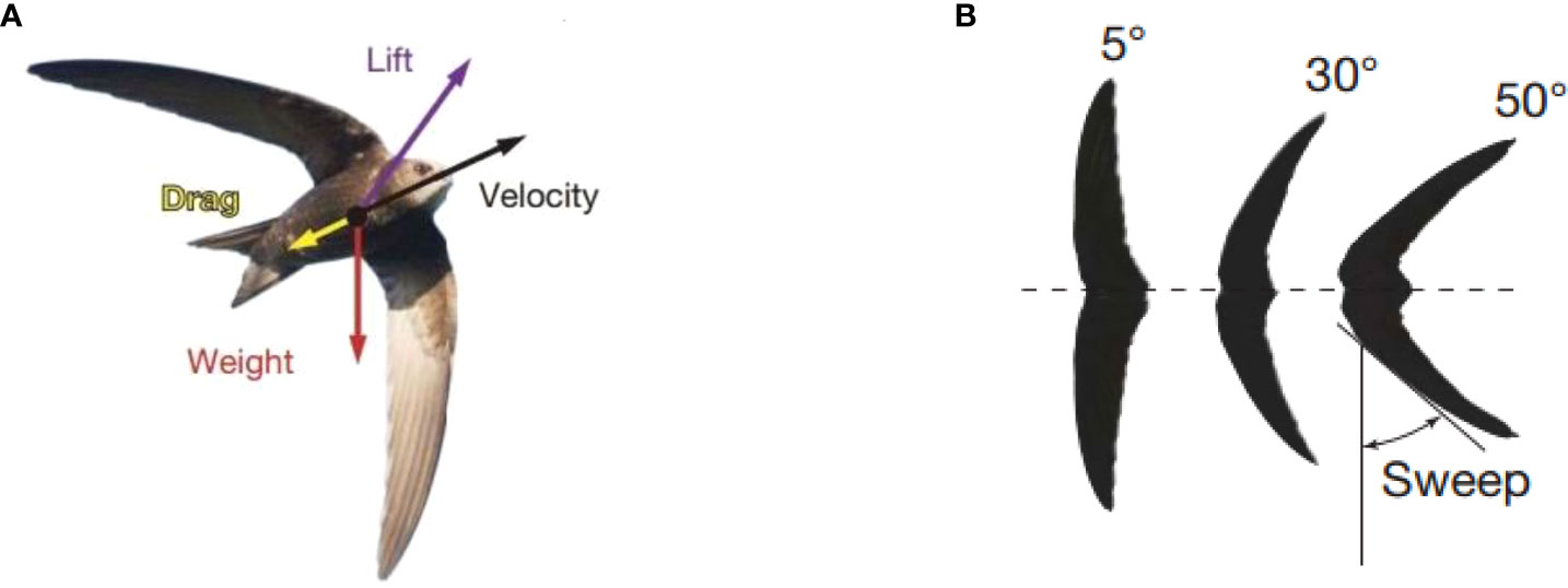
Figure 1 Swift (A) and its wings (B) (Lentink et al., 2007).
In this study, the bio-inspired strategy mainly refers to flight modes realized by swift based on variable sweep wing, which belongs to the bionics of flight mode. Similar to the swift, the UG also has two glide modes according to the specific observation mission, including the regular low-speed glide and the high-speed glide when passing through a current. To obtain a smooth high-density dataset (Benoit-Bird et al., 2018) and sample turbulent waters for longer duration (Fer et al., 2014), the UG generally adopts the wings with a small sweep angle to realize low-speed glide, which is the better appropriate glide mode in certain situations. According to Leonard et al. (2007), slow, high-endurance vehicles might be more useful for larger scales, whereas fast, low-endurance vehicles might serve better collecting data over smaller scales. However, when passing a strong eddy boundary (Jones et al., 2014) and high currents (Claus et al., 2010; Carneiro et al., 2021), the UG needs to adopt the wings with a large sweep angle to obtain a high speed. Therefore, by simulating the flight modes of swift with variable sweep angle, the UG can be equipped with pre-adjustable sweep wings to realize different motion modes and carry out different observation missions more perfectly.
In this paper, a sweep wing strategy inspired by the actual swift wings is established, as shown in Figure 2. The wings are articulated with the body of UG, L is the wing span. Figure 2B shows the relationship between the wing area and the aspect ratio with sweep angle θs which can change from 7° to 60°. The area of single wing Swing is described rectangle OAiBiDi at arbitrary sweep angle θsi, which can be calculated as
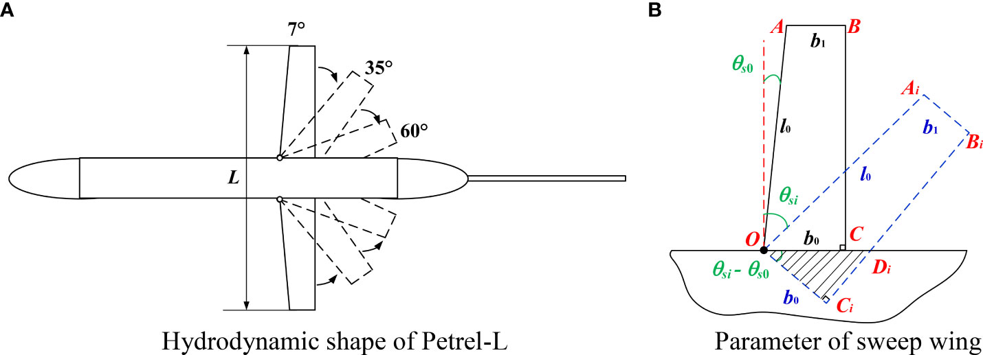
Figure 2 Hydrodynamic shape of Petrel-L with various sweep wings. (A) Hydrodynamic shape of Petrel-L (B) Parameter of sweep wing.
where b0 and b1 are chord of the wing root and tip, respectively, and l0 is the length of wing leading edge.
The wing aspect ratio λ is described with the average chord bav simple because that is not a standard rectangle.
where D is the glider diameter.
The corresponding variations of the wing area and the aspect ratio are shown in Figure 3, which indicates that the wing area and the aspect ratio decrease from 0.183 m2 and 4.8 to 0.138 m2 and 2.8 respectively when the sweep angle increases from 7° to 60°.
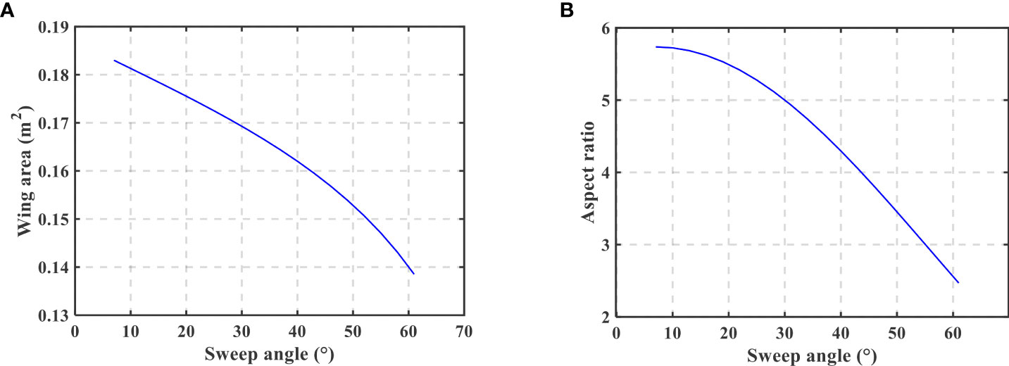
Figure 3 Variations of the wing area (A) and the aspect ratio (B).
Dynamic modeling of UG
This paper takes Petrel-L underwater glider (Yang et al., 2019), developed by Tianjin University, China, as the research object, and the structure of the glider is shown in Figure 4. Petrel-L can adjust its buoyancy by transferring the oil between the internal oil tank and the external bladder, which leads to its vertical motion. The horizontal motion is realized by the lift generated by its wings. Thus, UG moves follow the zigzag trajectory. By translating and rotating the movable internal mass block, the attitude of UG can be adjusted. To analyze the glide performance of UG with various sweep wings, a dynamic model is established in this paper.
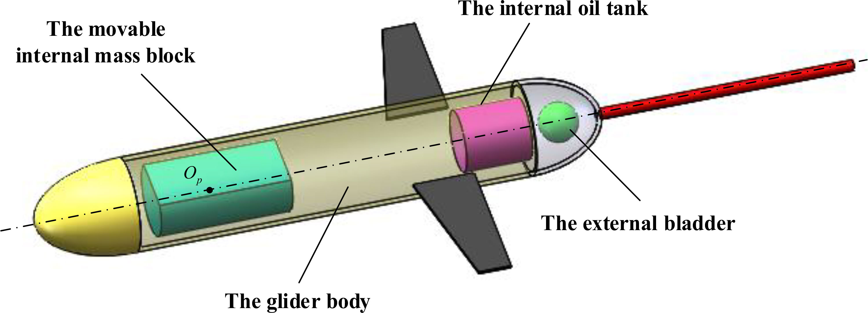
Figure 4 Structure diagram of Petrel-L.
Coordinate frames and kinematic equations
To facilitate the subsequent deduction, three coordinate frames are established firstly, including the inertial frame E-XYZ, body frame O-xyz and velocity frame O’-x’y’z’ shown in Figure 5. The origin of inertial frame is fixed to the initial location of UG on the sea surface, in which the motion trajectory of UG can be expressed. The direction of the X-axis is same as the initial heading of UG on the sea surface, and the direction of the Z-axis is vertically downward with the sea surface. The origin of the body frame is fixed to the center of buoyancy. The direction of the x-axis is coincident with that of the axis of UG, and the direction of the z-axis is vertically downward with the x-axis. As for the velocity frame, the origin of it coincides with the body frame and the O’-x’ axis points to the velocity direction of UG. The O’-z’ axis is vertically downward with the O’-x’ axis, which is in the plane O-xz. Other axes are determined by right-hand rule.
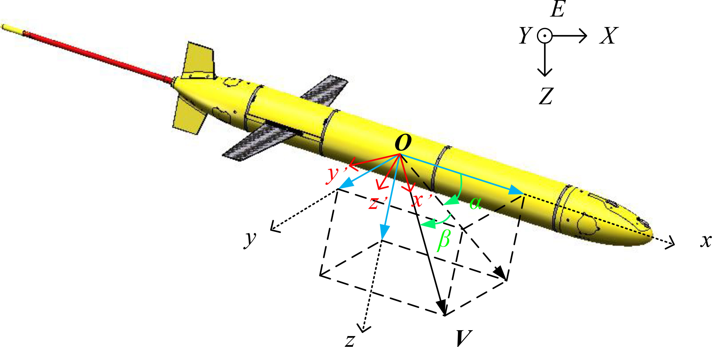
Figure 5 Coordinate frames of UG.
The position and the attitude of UG in the inertial frame can be expressed by position vector b= [X, Y, Z]T and η= [φ, θ, ψ]T. The φ, θ and ψ respectively denote the angles that the body frame rotates along the X-axis, Y-axis and Z-axis from the attitude coinciding with the internal frame, which are called roll angle, pitch angle and yaw angle, respectively. The inertial frame E-XYZ can be coincident with the body frame O-xyz after rotating, the rotation matrix between which can be expressed as (Fossen, 2011)
The rotation matrix from the body frame to the inertial frame is the transpose of . The velocity and the angular velocity of UG in the body frame are defined as velocity vector V= [u, v, w]T and angular velocity vector Ω= [p, q, r]T, which are the velocities and angular velocities along the x-axis, y-axis and z-axis respectively. The rotation matrix from the body frame to the velocity frame can be expressed as
Similarly, the rotation matrix from body frame to inertial frame is the transpose of . The velocity V of UG can be calculated as
According to the (Fossen, 2011), the angle of attack α and the sideslip angle β can be expressed as
According to the (Fossen, 2011), the kinematic differential equations of the UG are as follows
Force analysis
Usually, the buoyancy of the whole UG B0 can be equivalent to a concentrated exerted on its buoyancy center O. The net buoyancy is denoted as ΔB. In the motion process, the UG is also subjected to the gravity Gh, the gravity of the movable internal mass block Gp, the inertial hydrodynamic force Fm, and the viscous hydrodynamic force Fs. The additional moments may be generated when the above forces are moved to O, which are defined as Mb, Mh, Mp, Mm and Ms respectively (Wu et al., 2020).
In addition, the position vector of the barycenter relative to the origin of the body frame is denoted as rh. The position vector of the buoyancy center of the external bladder relative to O is denoted as rb. Under the standard state, the position vector of the movable internal mass block barycenter relative to O is denoted as rp. Then the position change vector of Op is denoted as Δr. Here rh, rb, rp and Δr are all expressed in the body frame. Since the directions of both gravity and buoyancy are always parallel to the Z-axis of the inertial frame, in the body frame, the expressions of Gh, Gp, B0, ΔB, Mh, Mp and Mb are (Wu et al., 2020)
where g represents the acceleration of gravity, ρ is the density of seawater, Vb is the volume change amount of the external bladder, mp is the movable internal mass and mh is the mass of the glider excluding mp.
Since Petrel-L is symmetrical relative to the O-xz plane in the body frame, the expressions of the inertial hydrodynamic force and inertial hydrodynamic moment can be expressed as
where λ11, λ22 and λ33 represent the added mass; λ44, λ55 and λ66 represent the added moment of inertia; λ26, λ35, λ53 and λ62 represent the added static moment.
According to (Jones et al., 2002; Fossen, 2011), the viscous hydrodynamic force Fs = [D, SF, L]T and viscous hydrodynamic moment Ms = [Mx’, My’, Mz’]T can be expressed as
where D, SF and L are the hydrodynamic forces in the velocity frame along with the x’-axis, y’-axis and z’-axis respectively, Mx’, My’ and Mz’ are the hydrodynamic moments in the velocity frame along with the x’-axis, y’-axis and z’-axis respectively, ρ0 is the in-situ density, A is the cross sectional area of UG, CD, CSF and CL are hydrodynamic force coefficients and Cx’, Cy’ and Cz’ hydrodynamic moment coefficients, which can be obtained by experimental and computational fluid dynamics method.
Dynamic modeling
The dynamic model of UG is established by the linear momentum theorem and angular momentum theorem. Due to the neglect of the changing process of control parameters values, the dynamics modeling omits the mutual movement process between the movable internal mass block and the glider body.
In the inertial frame, the linear momentum and the angular momentum of UG relative to E are defined as PE and LE. In the body frame, the linear momentum and the angular momentum of UG relative to O are defined as PB and LB. Since the barycenter of the whole UG does not coincide with O, PB and LB can be expressed as
where Jo represents the inertia tensor of UG relative to the body frame, which is obtained based on the inertia tensor Jp of the movable internal mass block relative to its barycenter, the inertia tensor Jh of UG relative to its barycenter and the parallel axis theorem, rg represents the position vector of the whole glider barycenter relative to O shown as
According to the kinematic relation, there are
where the operators ^ maps a vector to the matrix representation of the vector cross product operator (Leonard and Graver, 2001).
According to the Newton’s second law, there is
where f and τ are the resultant force and resultant moment in the inertial frame, respectively. According to the Eq. (18) and Eq. (21), there is
The resultant force F and resultant moment M in the body frame can be ascertained by sum of Eq. (11) to Eq. (16).
Substituting Eq. (14) into Eq. (20), Eq. (21) can be obtained as
Combining Eq. (9), Eq. (10) and Eq. (24), the dynamic model of UG is established.
Viscous hydrodynamic coefficients of UG with various sweep wings
The correctness of the dynamic model established above has been verified by Petrel-L glider in our previous work (Yang et al., 2021). However, it cannot be directly used in the motion simulation of UG with various sweep wings due to its variable hydrodynamic coefficients, including CD, CSF, CL, Cx’, Cy’ and Cz’. Usually, these hydrodynamic coefficients of a constant hydrodynamic shape can be obtained by computational fluid dynamics (CFD) method. For a variable hydrodynamic shape of UG with various sweep wings, it will lead to low efficiency, large time consumption, and huge amount of data to carry out performance analysis by directing combing hydrodynamic numerical simulation. In this paper, an approximate model is applied to replace the fluid computation, which is commonly used in complex engineering design to minimize the computational expense of running complex and high-fidelity simulations (Sobester et al., 2008).
Approximate model, established by a few sample points, is based on the mathematical statistics, which can replace the complex engineering model and be used in optimization with the premise of ensuring reasonable accuracy. Compared with the traditional engineering model, the optimization with the approximate model has the advantages of low computation and high computational efficiency, which can effectively relieve the calculation pressure, shorten the development cycle, reduce the cost, and improve the hydrodynamic performance. It is a common technical method for engineering optimization problems with many design variables and high test cost.
In this study, the establishment process of approximate model can be summarized as follows.
Numerical experimental design
Experimental design is an important branch of mathematical statistics, which studies how to arrange the test scheme and improve the rationality of test sample distribution to reduce the impact of test error, and make the experimental results used in reasonable statistical analysis. Experimental design can be divided into two categories according to the design idea: classical experimental design and experimental design based on space filling.
Classical experimental design, developed from traditional physical experimental design, usually distributes most sample points on the boundary of design space to reduce random error, such as factorial designs, central composite designs and orthogonal designs. With the continuous improvement of computing power and the development of numerical simulation software, the main object of experimental design has changed from traditional physical experiment to numerical experiment. In order to reduce the system error and improve the space exploration of the test scheme, the sampling points should be evenly covered throughout the design space, based on which the experimental design based on space filling developed, such as uniform designs, Latin hypercube designs and optimal Latin hypercube designs.
In this study, the hydrodynamic coefficients are calculated by CFD method, including the flume and the rotating arm pool numerical experiment. The flume experiment is used to obtain the hydrodynamic coefficients related to the velocity direction of UG, the design space of which is shown in Table 1. The rotating arm pool experiment is used to obtain the hydrodynamic coefficients related to the angular velocities, and the design space is shown in Table 2.
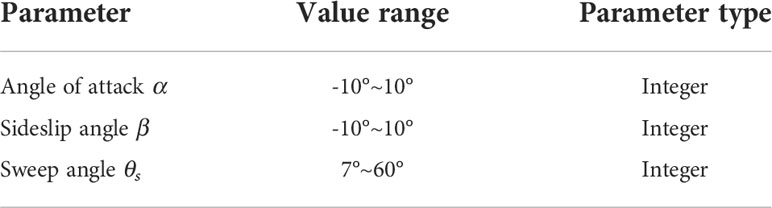
Table 1 Design space in flume experiment.
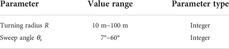
Table 2 Design space in rotating arm pool experiment.
Due to the characteristic of less design variables, this paper adopts optimal Latin hypercube designs to sample from the design space. In this paper, the initial number of sample points is set as 200. As shown in Figure 6, the sample points in the two tests uniformly distribute in the design spaces.
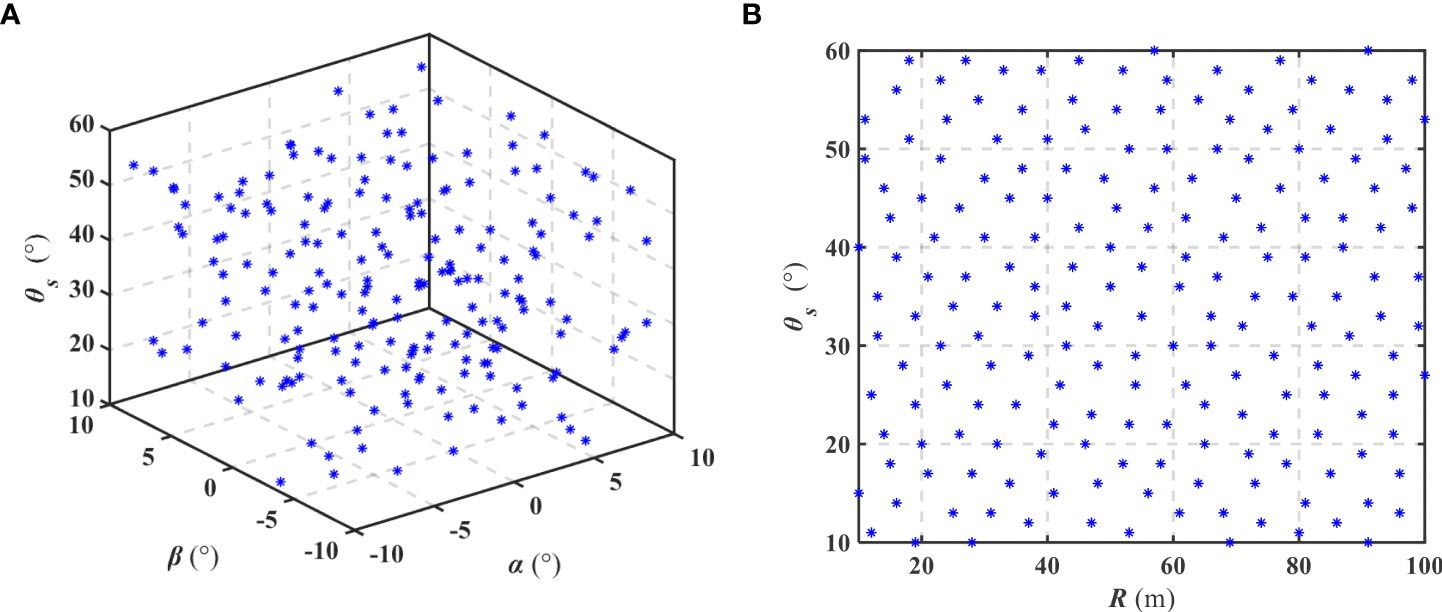
Figure 6 Sample points of the flume experiment (A) and rotating arm pool experiment (B).
Based on the sample points in the experimental design, the CFD is adopted to obtain the relevant hydrodynamic coefficients for establishment of approximate models. Firstly, a parameterized 3D hydrodynamic shape of Petrel-L with pre-adjustable sweep wings is established, as shown in Figure 7, which can change the wing shape according to sweep angle in the sample data.
Figure 7 Parameterized model of hydrodynamic shape.
Then, the model is imported into the software ICEM to generate the mesh. The computation domain further away from the glider hull uses unstructured meshes, and the computational domain closer to the glider hull uses prism meshes to enhance the mesh quality near the glider surface. The number of grid boundary layer nodes is 10, and the distance of the first layer grid is adjusted to ensure y+< 5. The mesh map of computational domain and surface for Petrel-L is shown in Figure 8.
Figure 8 Mesh map of computational domain and surface for Petrel-L.
Then, to validate the independence of the mesh for obtaining accurate results, the drag of the case (velocity 1 m/s, angle of attack 0°, sideslip angle 0° and sweep angle 7°) with four types of mesh quantities have been calculated, and the results are listed in Table 3. Considering the trade-off between simulation accuracy and efficiency, the grid quantity of 3.343 million is finally imported into the software ANSYS Fluent to calculate the hydrodynamic coefficients of all cases.
Table 3 Grid independence verification results.
In terms of outflow field simulation, the computational domain should be set large enough to avoid the influence of domain boundary (Fu et al., 2018; Sun et al., 2021). Referring to the above research and considering our practical situation, computational domain of flume experiment is set as 3Lglider × 3Lglider ×7Lglider (Lglider is the total length of the glider) in this study, as shown in Figure 9. In addition, the computational domain of rotating arm pool experiment is ring-shaped and set as 6Lglider × 1.5Lglider ×1.5Lglider. The total arc length of the centerline of the ring is 6Lglider, and the arc length along the centerline from the buoyancy center of glider to the inlet is 2Lglider. Other boundary conditions of computational domain are the same as flume experiment. In the CFD solver, k-ω shear stress transport turbulence model is employed because it not only provides the best prediction of vortex distribution around underwater vehicles but also strikes a good balance between computational cost and convergence stability (Jagadeesh et al., 2009).

Figure 9 Boundary conditions of numerical simulation in flume experiment.
Figure 10 show the velocity contours in the flume and rotating arm pool numerical experiment respectively, in which the velocity is uniformly set as 0.5 m/s.
Figure 10 Velocity contours in the CFD simulation.
Although the application of approximate model can reduce the calculating amount for obtaining the hydrodynamic coefficients of UG with various sweep wings, it will still consume a lot of manpower to repeat the process of calculation with CFD solver for 200 times. Thus, we construct an automatic solution platform in software iSight by command streams of CATIA, ICEM and ANSYS Fluent, which can automatically update the 3D model, divide the mesh and calculate the coefficients according to the sample points.
Establishment of approximate model
The approximate mode is an effective tool that describes arbitrary nonlinear system of inputs and the corresponding outputs. The method of establishing it mainly including polynomial fitting method, Kriging interpolation method and neural network interpolation method. Among them, the polynomial fitting method has a unique superiority with relatively computational convenient and acceptable accuracy. Therefore, the polynomial fitting method is employed to establish approximate models in this paper based on 1stOpt which is a general nonlinear fitting software platforms.
Before establishing the approximate models, the correlation analysis is firstly performed with the collected data to determine the influence rule between the design variables and the hydrodynamic coefficients, by which we know that each hydrodynamic coefficient shall be fitted by which variables. The hydrodynamic coefficients obtained in flume and rotating arm pool numerical experiment, and their relevant variables are shown in Figures 11 and 12 respectively.
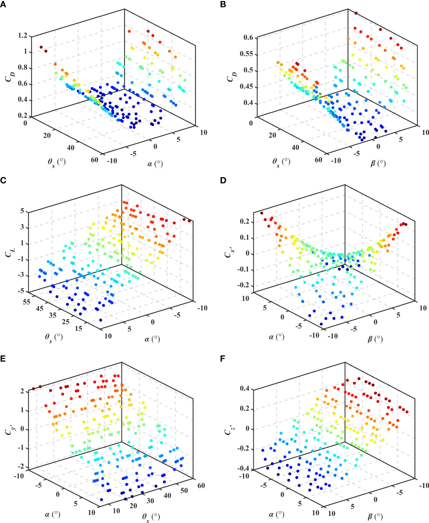
Figure 11 Hydrodynamic coefficients obtained in flume numerical experiment.

Figure 12 Hydrodynamic coefficients obtained in rotating arm pool numerical experiment.
In this study, the derivative of angular velocity p in the coefficient Cx’ is set as a constant (-0.62) due to its negligible effect. The approximate models of hydrodynamic coefficients, shown in Eq. (22), can be obtained with randomly selected 75% of data points. The other 25% of the points are used to verify the accuracy of the approximate models by contrasting the calculation results. All of the multiple correlation coefficient (R2) between the CFD simulations and the approximate models are more than 0.99, which indicated that we don’t need increase the number of sample points and the approximate models can be imported into the dynamic model to analyze the performance of UG with various sweep wings.
In Eq. (22), the unit of angle is radian. To identify the influence of design variables on hydrodynamic coefficients, the Sobol’ method (Sobol′, 1990) is applied, the process of which mainly includes the following four steps. Step 1: Select parameters. Step 2: Confirm the ranges and distributions of parameters. Step 3: Generate samples. Step 4: Calculate the sensitivity indexes. The sensitivity indexes can be calculated by (Sobol′, 2001). According to sensitivity analysis results, the sweep angle θs has an influence on the drag coefficient CD, lift coefficient CL, and moment coefficient Cy’. Obviously, the CD is mainly determined by the α and β, and θs has no significant effect on it. Because the change of sweep angle θs directly affects the wet-surface of wing. The CSF and β meet the linear relationship after ignoring the high-order infinitesimal. The influence of α and θs on CL is opposite. The increase of θs will directly reduce the wing area and aspect ratio of wing, shown in Figure 3, which will reduce the lift coefficient CL of UG.
Performance analysis of UG with various sweep wings
With the demand increase of ocean observation mission in time and space, endurance ability is gradually becoming one of the most important factors for UGs. In addition, a high trajectory accuracy of UG is also required in some observation missions to reduce the observation error. Thus, the endurance ability and trajectory accuracy are referred to as the indexes to analyze the performance of UG with various sweep wings. Three indexes related to the endurance ability are: (1) gliding range (expressed as the maximum glide ratio), (2) gliding duration, and (3) turn angle (variation of heading angle) for a given depth loss. By maximizing range or time spent gliding, UG can satisfy the demand of some observation mission in space and time respectively. The high trajectory accuracy requires (4) fast turns (high angular velocity) with (5) a small turn radius, and (6) high horizontal velocity to avoid drift in ocean currents.
By importing the hydrodynamic coefficients into the dynamic model, the above indexes can be obtained to analyze the performance of Petrel-L with various sweep wings. The net buoyancy is set as different values due to the buoyancy loss of UG. Thus, by giving the different net buoyancy (1-8 N) and sweep angle (7-60°), the six indexes can be calculated, as shown in Figures 13A–F. Figures 13A, B indicate that UG with extended wings (θs=7°) has a larger glide ratio and duration than that with variable sweep angle for the constant angel of attack. Figures 13C–E indicate that there exist the optimal sweep angles for turning, with which UG has the largest turn angle for a depth loss (θs=35.12°), the smallest turn radius (θs=35.12°) and the largest angular velocity (θs=36.45°). Figure 13F shows that UG with sweep wings has a larger horizontal velocity than that with extended wings.
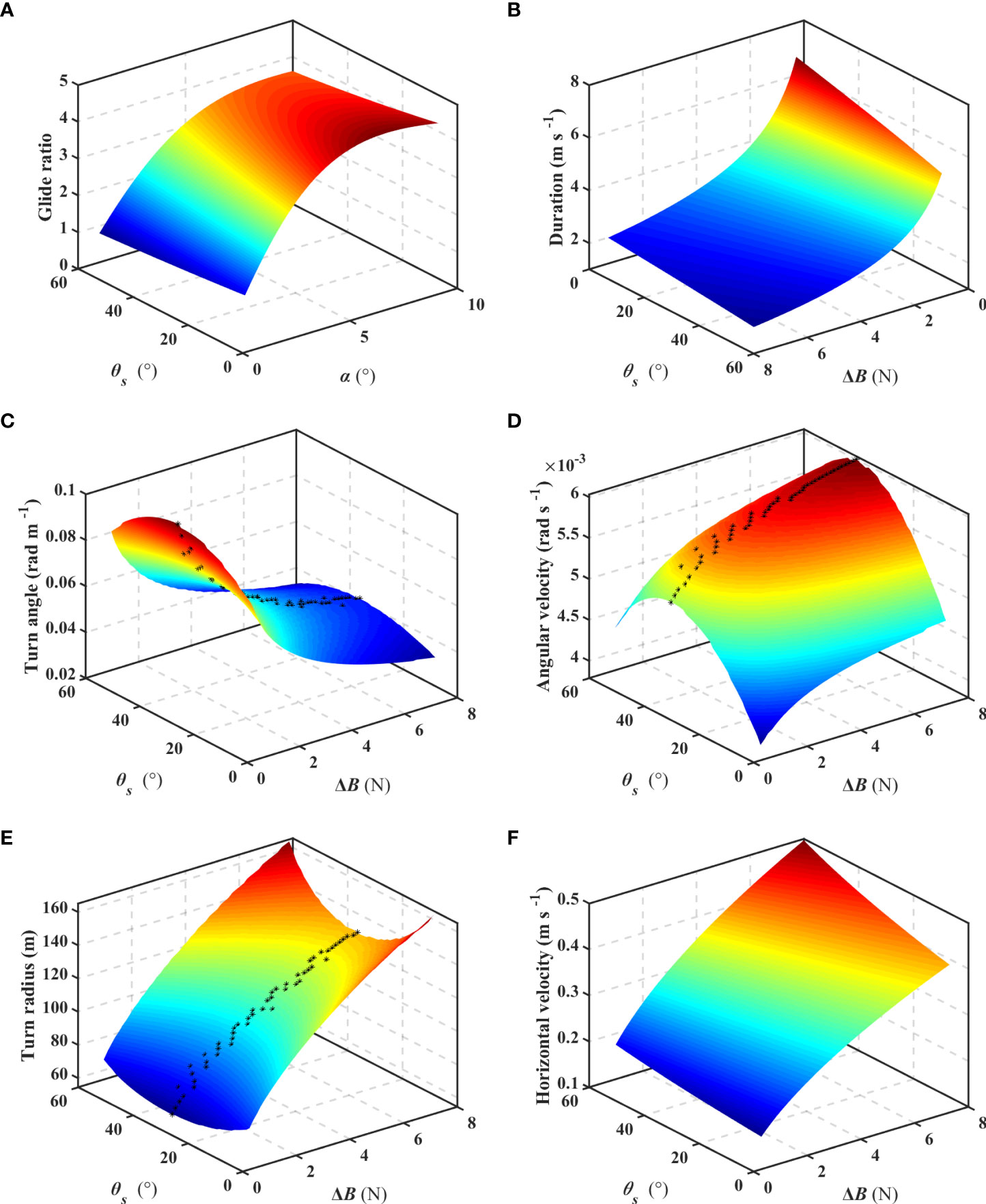
Figure 13 The indexes of UG with pre-adjustable sweep wings.
Petrel-L with extended and sweep wings provided the largest glide ratio and the best ability of resisting ocean currents respectively. Petrel-L with a sweep angle (around 35°) of wings has the best turn ability, which can reduce the trajectory error caused by heading adjustment of Petrel-L.
Glide ratio and duration analyzed above can represent the gliding range and gliding duration of swifts due to their negligible hotel load when gliding. However, unlike the swifts, the hotel load of UG, varying with the type of carried sensors and sampling frequency, is an important component of energy consumption of UG, which may have an influence on the gliding range and duration. Thus, the gliding range and gliding time per energy consumption unit are referred as to the indexes to analyze the gliding range and gliding duration of Petrel-L.
Figure 14 shows the gliding range per energy consumption unit, denoted by e, with the different hotel loads (0.5-2 W), in which the black points represent the maximum value with a given net buoyancy. Figure 14 indicates that the optimal sweep angle for largest gliding range transforms from the 60° to the 7° with the net buoyancy for a given hotel load, where the net buoyancy is defined as Bt. Petrel-L with sweep wings or extended wings has larger gliding range when its net buoyancy is smaller or larger than Bt. As shown in Figure 15, the net buoyancy Bt increases with the hotel load.
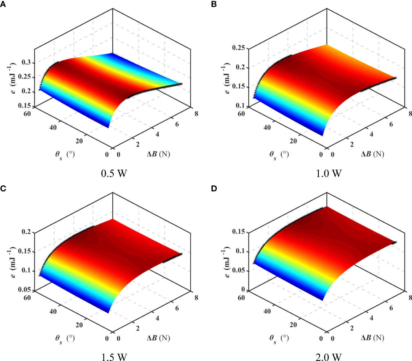
Figure 14 Gliding range per energy consumption unit. (A) 0.5 W (B) 1.0 W (C) 1.5 W (D) 2.0 W.
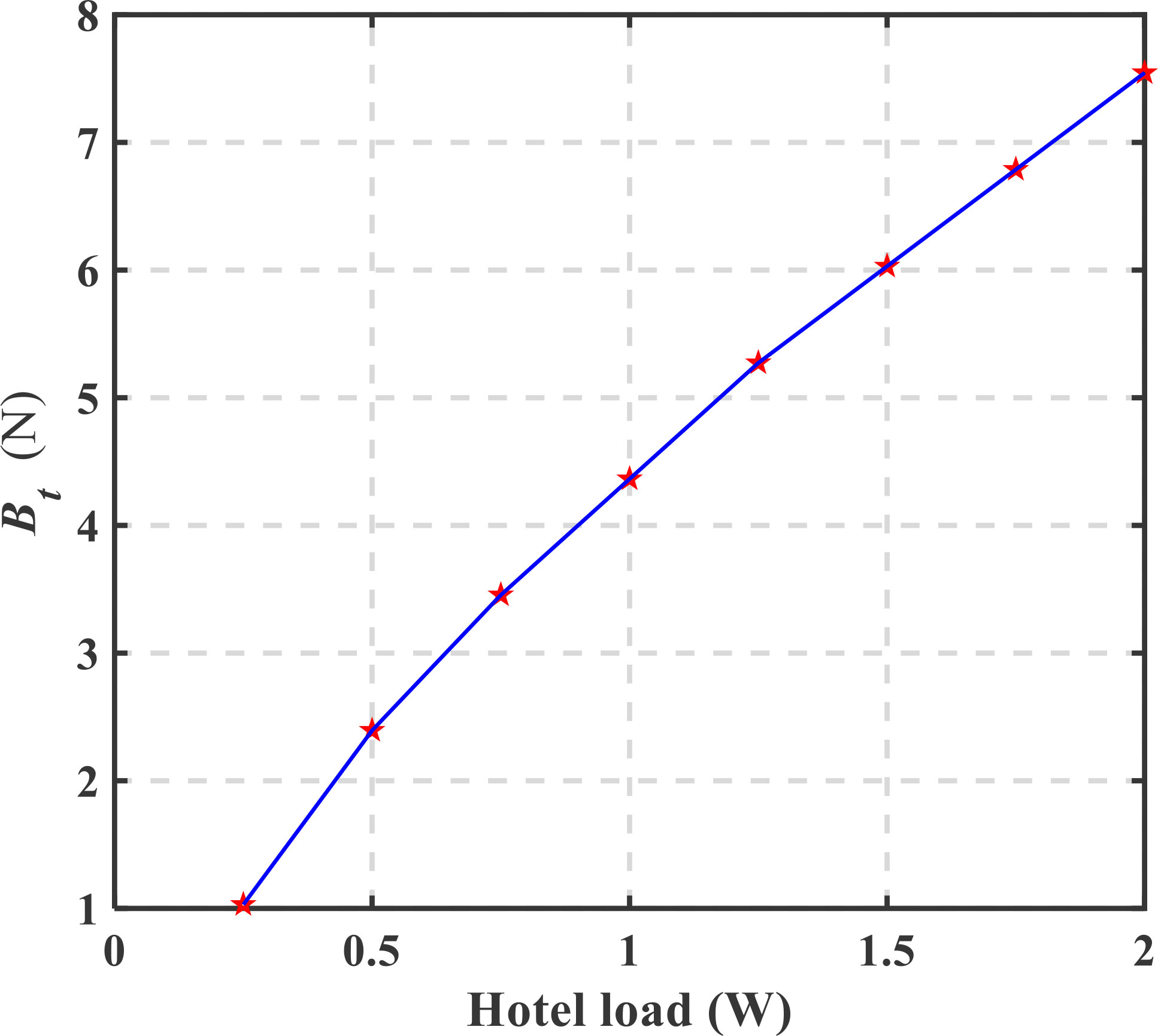
Figure 15 Variation of Bt with hotel load.
Figure 16 shows the gliding duration per energy consumption unit, denoted by η, with the different hotel loads (0.5-2 W), in which the black points represent the maximum value with a given net buoyancy. The optimal sweep angle for gliding duration is invariable (6°) with the hotel load and net buoyancy, which indicates that Petrel-L with extended wings has a larger gliding duration than that with sweep wings.
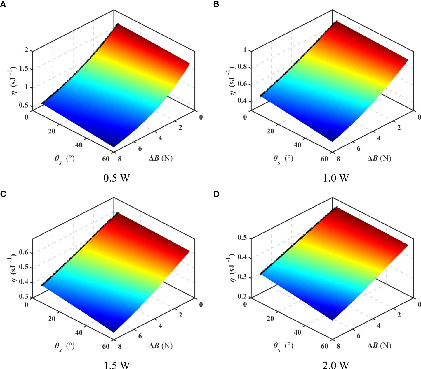
Figure 16 Gliding duration per energy consumption unit. (A) 0.5 W (B) 1.0 W (C) 1.5 W (D) 2.0 W.
To sum up, the relationship between the performance demand of UG and its sweep angle can be obtained. (1) Gliding range demand. To obtain the largest gliding range, Petrel-L need sweep back wings (60°) when the net buoyancy is smaller than Bt, and extend wings (7°) when it is larger than Bt. (2) Gliding duration demand. Petrel-L with extended wings (7°) is more suitable to obtain the largest gliding duration. (3) Trajectory accuracy demand. Petrel-L with wings (around 35°) has a better turn ability. (4) Resisting current demand. Petrel-L with sweep wings (60°) has a larger horizontal velocity to avoid drift in ocean currents.
This study aims to adopt pre-adjustable sweep wings for UGs with different glide modes in specific observation missions to obtain better performances, which also has a great economic value. In comparison, the wing structure with a variable sweep angle is not an appropriate way to improve the performance of UG, due to the complexity, weight penalty, and maintenance requirements, concluded as follows. 1) Variable sweep wings have the complexity of design, manufacturing and maintenance, resulting in a high cost. 2) The driving system of variable sweep wings will increase energy consumption and reduce the reliability of UG which is a low-power and high-reliability platform for long-term ocean observation. 3) It generally takes a long time for the UG to complete an observation mission which requires the glider to work in a relatively fixed glide mode. Therefore, compared with variable sweep angle, the strategy proposed in this paper of pre-adjustable sweep wings depending on task-orientation before the deployment is an optimal individualized design, which can balance performance and reliability of underwater glider at the current stage.
Verification
The reliability verification of CFD method by circulating flume test is significant and widely applied in ship and ocean engineering fields (Wang et al., 2018; Bie and Li, 2022). To verify the correctness of the CFD method and the performance analysis of Petrel-L, a circulating flume test is carried out by Petrel-L with extended wings (7°), which can be expended to cover more of the range of sweep angles. In the circulating flume test, the oblique towing motion of vertical plane and horizontal plane of Petrel-L are performed to obtain the relevant hydrodynamic coefficients. The vertical plane measurement of Petrel-L in circulating flume are shown in Figure 17.
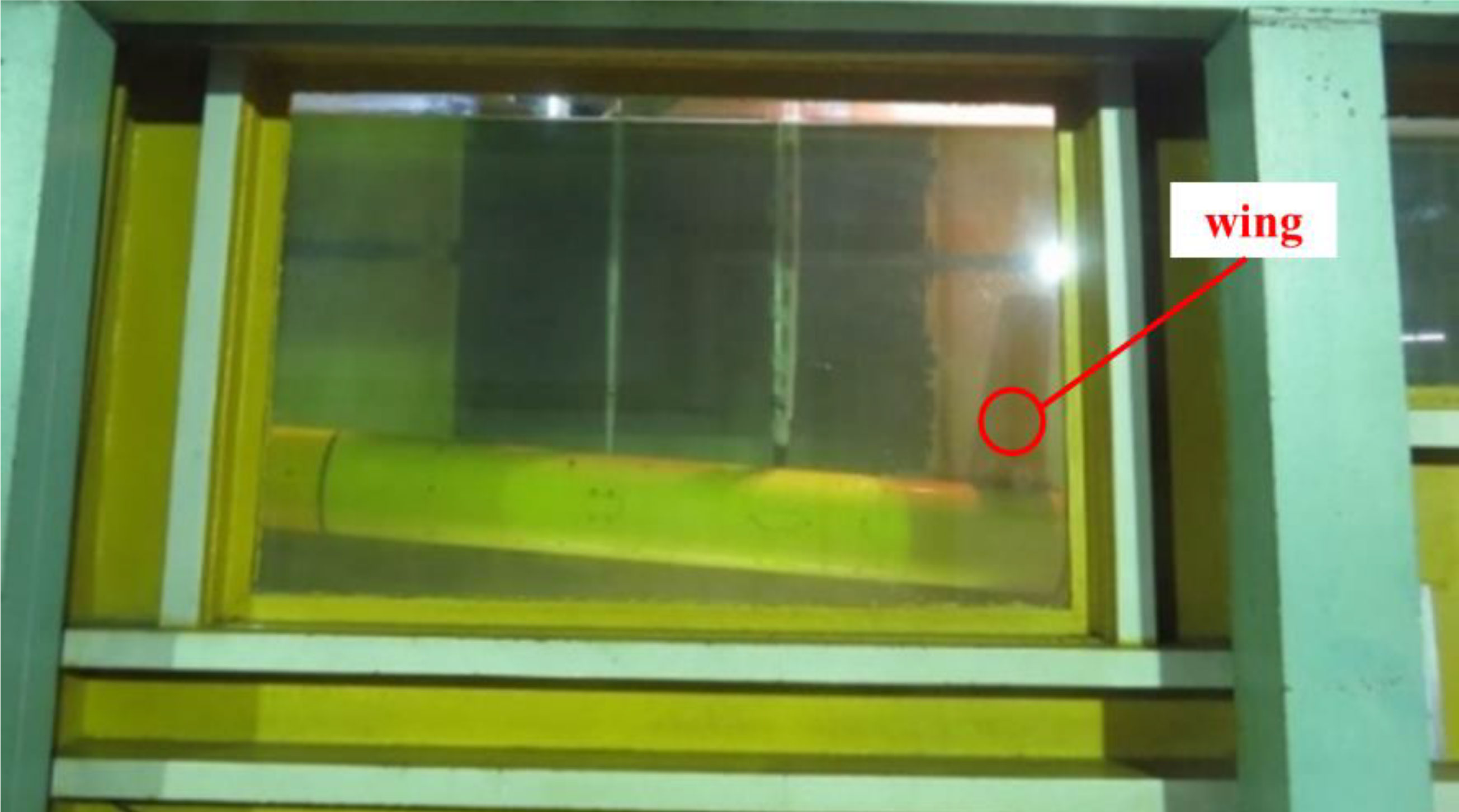
Figure 17 Equipment and glider in circulating flume test.
In the circulating flume test, the directions of O-x axis, O-y axis and O-z axis of the forces are directly measured. To facilitate comparison with CFD simulation, the results of circulating flume tests are transformed from body frame to velocity frame. Figures 18A–F show the comparison of CFD simulation results and circulating flume test results measured in horizontal plane and vertical plane. In the figures, the fitted curve of the experimental results is indicated with red dotted line, and the multiple correlation coefficient R2 of fitted curve is presented. Meanwhile, the correlation coefficient ρ between CFD simulation results and flume test results is marked with red triangles. According to analysis of R2 and ρ, the CFD simulation results are basically in accordance with the flume test results.
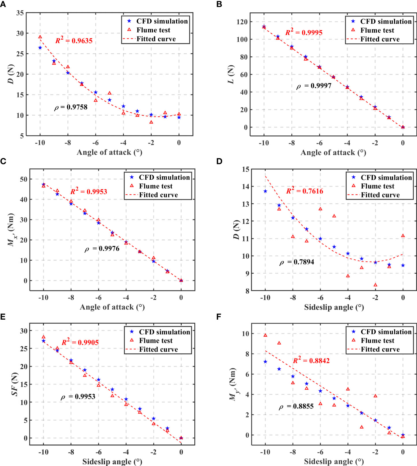
Figure 18 Results of circulating flume test and CFD simulation.
To further analyze distribution of the error data, the absolute error between CFD simulation and flume test is calculated, as shown in Figure 19. The absolute error of all case is dispersed in the interval [-2, 2], and the absolute error of L-α and SF-β has obvious bias. The error between CFD simulation and flume test results is analyzed, which can be attributed to the following aspects. 1) The support frames of UG in the flume test have a slight vibration due to water flow. 2) The viscosity and density of water in simulation are inconsistent with those in the test. 3) Due to the limitation of the size of the flume, the walls may affect hydrodynamic force of the UG model in the test.
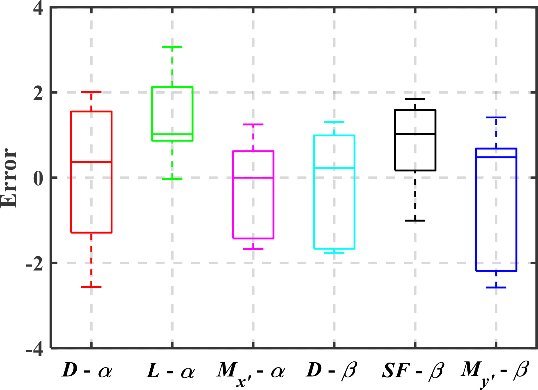
Figure 19 The absolute error of CFD simulation and flume test.
Conclusions
Inspired by the flight modes of swift, a sweep wing strategy is proposed to apply pre-adjustable sweep wings before the deployment of UGs, so as to improve the glide performance in different glide conditions. To facilitate the performance analysis of UG with various sweep wings, the approximate models of the hydrodynamic coefficients are established based CFD method to express the relationship between hydrodynamic coefficients and wing sweep angles. By importing the approximate models into the dynamic model of UG, the performance analysis of UG with various sweep wings related to endurance ability and trajectory accuracy are performed. The circulating flume test verifies the validity of the CFD method and the following conclusions can be drawn.
(1) The sweep angle of wings has obviously influence on motion performance of Petrel-L. Petrel-L with a sweep angle of 7°, 35° and 60° can obtain the largest gliding time, the best turn ability and the best resisting current ability respectively.
(2) To obtain the largest gliding range, Petrel-L need transform the sweep angle from 60° to 7° when the variable net buoyancy is larger than Bt, which is determined by the hotel load of Petrel-L.
(3) The sweep wing strategy of UG proposed in this paper is useful for UG to obtain the optimal ability in some aspects, such as gliding range, gliding duration, trajectory accuracy and resisting current.
In the practical engineering, the specific ability demand of UG, such as gliding range, gliding duration, trajectory accuracy and resisting current ability, can be obtained from the observation missions, and the motion strategy of UG can be determined to obtain the optimum performance. In addition, the strategy need be adjusted in real time due to uncertainty of ocean environment in the process of ocean observation. Therefore, the design and application of wing mechanism of a variable sweep angle with lightweight, low power consumption and high reliability will be considered to further improve the task observation efficiency of UG in the future work.
Data availability statement
The raw data supporting the conclusions of this article will be made available by the authors, without undue reservation.
Author contributions
YW: Funding acquisition, Project administration, Conceptualization. CW: Methodology, Software, Data Curation, Writing - original draft. MY: Conceptualization, Writing - original draft, Validation, Investigation. YL: Investigation. WH: Experiment, Data curation. SY: Supervision, Funding acquisition. All authors contributed to the article and approved the submitted version.
Funding
This work was jointly supported by the National Key R&D Program of China, the National Natural Science Foundation of China (11902219 and 51721003), the Natural Science Foundation of Tianjin City (18JCJQJC46400), and Aoshan Talent Cultivation Program of QNLM (2017ASTCP-OE01). The authors also would like to express their sincere thanks to L. Ma to revise the grammar.
Conflict of interest
The authors declare that the research was conducted in the absence of any commercial or financial relationships that could be construed as a potential conflict of interest.
Publisher’s note
All claims expressed in this article are solely those of the authors and do not necessarily represent those of their affiliated organizations, or those of the publisher, the editors and the reviewers. Any product that may be evaluated in this article, or claim that may be made by its manufacturer, is not guaranteed or endorsed by the publisher.
References
Benoit-Bird K. J., Patrick Welch T., Waluk C. M., Barth J. A., Wangen I., McGill P., et al. (2018). Equipping an underwater glider with a new echosounder to explore ocean ecosystems: Echosounder equipped glider. Limnol. Oceanogr. Methods 16, 734–749. doi: 10.1002/lom3.10278
Bie D., Li D. (2022). Numerical analysis of the wing–wake interaction of tandem flapping wings in forward flight. Aerosp. Sci. Technol. 121, 107389. doi: 10.1016/j.ast.2022.107389
Bulekov V. P., Teryev E. D. (1972). Dynamics of variable sweep wing aircraft in the course of changing geometry. IFAC Proc. 5, 153–162. doi: 10.1016/S1474-6670(17)68464-7
Carneiro J. F., Pinto J. B., Gomes de Almeida F., Cruz N. A. (2021). Variable buoyancy or propeller-based systems for hovering capable vehicles: An energetic comparison. IEEE J. Ocean. Eng. 46, 414–433. doi: 10.1109/JOE.2020.3000703
Claus B., Bachmayer R., Williams C. D. (2010). Experimental flight stability tests for the horizontal flight mode of a hybrid glider. 2010 IEEE/OES Autonomous Underwater Vehicles, 1–6. doi: 10.1109/AUV.2010.5779680
Dobbs S. K., Miller G. D., Stevenson J. R. (1985). Self-induced oscillation wind tunnel test of a variable sweep wing. 26th Structures Struct. Dynamics Materials Conf. 739:1–16. doi: 10.2514/6.1985-739
Ellington C. P. (1999). The novel aerodynamics of insect flight: applications to micro-air vehicles. J. Exp. Biol. 202, 3439–3448. doi: 10.1242/jeb.202.23.3439
Fer I., Peterson A. K., Ullgren J. E. (2014). Microstructure measurements from an underwater glider in the turbulent faroe bank channel overflow. J. Atmospheric Ocean. Technol. 31, 1128–1150. doi: 10.1175/JTECH-D-13-00221.1
Fu X., Lei L., Yang G., Li B. (2018). Multi-objective shape optimization of autonomous underwater glider based on fast elitist non-dominated sorting genetic algorithm. Ocean Eng. 157, 339–349. doi: 10.1016/j.oceaneng.2018.03.055
Gursul I., Vardaki E., Wang Z. (2006). Active and passive control of reattachment on various low-sweep wings. 44th AIAA Aerospace Sci. Meeting Exhibit 506:1–21. doi: 10.2514/6.2006-506
Jagadeesh P., Murali K., Idichandy V. (2009). Experimental investigation of hydrodynamic force coefficients over AUV hull form. Ocean Eng. 36, 113–118. doi: 10.1016/j.oceaneng.2008.11.008
Javaid M. Y., Ovinis M., Hashim F. B. M., Maimun A., Ahmed Y. M., Ullah B. (2017). Effect of wing form on the hydrodynamic characteristics and dynamic stability of an underwater glider. Int. J. Nav. Archit. Ocean Eng. 9, 382–389. doi: 10.1016/j.ijnaoe.2016.09.010
Jones C., Allsup B., DeCollibus C. (2014). “Slocum Glider: Expanding our understanding of the oceans,” in OCEANS, 2014. 1–10, IEEE.
Jones D. A., Clarke D. B., Brayshaw I. B., Barillon J. L., Anderson B. (2002). The Calculation of Hydrodynamic Coefficients for Underwater Vehicles. (Australia: Technical report DSTO Platforms Sciences Laboratory).
Jones K. D., Platzer M. F. (2009). Design and development considerations for biologically inspired flapping-wing micro air vehicles. Exp. Fluids 46, 799–810. doi: 10.1007/s00348-009-0654-1
Kilgore R. A. (1971). Some transonic and supersonic dynamic stability characteristics of a variable-sweep-wing tactical fighter model. NASA Langley Research Center, 1–44.
Krashanitsa R., Silin D., Shkarayev S., Abate G. (2009). Flight dynamics of a flapping-wing air vehicle. Int. J. Micro Air Veh. 1, 35–49. doi: 10.1260/1756-8293.1.1.35
Lentink D., Muller U. K., Stamhuis E. J., de Kat R., van Gestel W., Veldhuis L. L. M., et al. (2007). How swifts control their glide performance with morphing wings. NATURE 446, 1082–1085. doi: 10.1038/nature05733
Leonard N. E., Graver J. G. (2001). Model-based feedback control of autonomous underwater gliders. IEEE J. Ocean. Eng. 26, 633–645. doi: 10.1109/48.972106
Leonard N. E., Paley D. A., Lekien F., Sepulchre R., Fratantoni D. M., Davis R. E. (2007). Collective motion, sensor networks, and ocean sampling. Proc. IEEE 95, 48–74. doi: 10.1109/JPROC.2006.887295
Li D., Zhao S., Da Ronch A., Xiang J., Drofelnik J., Li Y., et al. (2018). A review of modelling and analysis of morphing wings. Prog. Aerosp. Sci. 100, 46–62. doi: 10.1016/j.paerosci.2018.06.002
Low K. H., Willy A. (2006). Biomimetic motion planning of an undulating robotic fish fin. J. Vib. Control 12, 1337–1359. doi: 10.1177/1077546306070597
Lyu D., Song B., Pan G., Yuan Z., Li J. (2019). Winglet effect on hydrodynamic performance and trajectory of a blended-wing-body underwater glider. Ocean Eng. 188, 106303. doi: 10.1016/j.oceaneng.2019.106303
Miller T. F. (2018). A bio-inspired climb and glide energy utilization strategy for undersea vehicle transit. Ocean Eng. 149, 78–94. doi: 10.1016/j.oceaneng.2017.11.048
Pendleton E. W., Bessette D., Field P. B., Miller G. D., Griffin K. E. (2000). Active aeroelastic wing flight research program: Technical program and model analytical development. J. Aircr. 37, 554–561. doi: 10.2514/2.2654
Petritoli E., Bartoletti C., Leccese F. (2021). Preliminary study for AUV: Longitudinal stabilization method based on takagi-sugeno fuzzy inference system. Sensors 21, 1866. doi: 10.3390/s21051866
Popov A. V., Grigorie L. T., Botez R., Mamou M., Mebarki Y. (2010). Real time morphing wing optimization validation using wind-tunnel tests. J. Aircr. 47, 1346–1355. doi: 10.2514/1.47431
Powers S., Webb L., Friend E., Lokos W. (1992). “Flight test results from a supercritical mission adaptive wing with smooth variable camber,” in 6th AIAA Biennial Flight Test Conference.
Raither W., Heymanns M., Bergamini A., Ermanni P. (2013). Morphing wing structure with controllable twist based on adaptive bending–twist coupling. Smart Mater. Struct. 22, 065017. doi: 10.1088/0964-1726/22/6/065017
Rojratsirikul P. (2013). Bio-inspiration in the wings of man-made flyers. J. Res. Appl. Mech. Eng. 1, 1–7.
Rosen M., Hedenstrom A. (2001). Gliding flight in a jackdaw: A wind tunnel study. J. Exp. Biol. 204, 1153–1166. doi: 10.1242/jeb.204.6.1153
Rudnick D. L. (2016). Ocean research enabled by underwater gliders. Annu. Rev. Mar. Sci. 8, 519–541. doi: 10.1146/annurev-marine-122414-033913
Rudnick D. L., Davis R. E., Eriksen C. C., Fratantoni D. M., Perry M. J. (2004). Underwater gliders for ocean research. Mar. Technol. Soc J. 38, 73–84. doi: 10.4031/002533204787522703
Sánchez P. J. B., Papaelias M., Márquez F. P. G. (2020). Autonomous underwater vehicles: Instrumentation and measurements. IEEE Instrum. Meas. Mag. 23, 105–114. doi: 10.1109/MIM.2020.9062680
Sobester A., Forrester A., Keane A. (2008). Engineering design via surrogate modelling: a practical guide (New York, USA: John Wiley & Sons).
Sobol′ I. M. (1990). On sensitivity estimation for nonlinear mathematical models. Mat. Model. 2, 112–118.
Sobol′ I. M. (2001). Global sensitivity indices for nonlinear mathematical models and their Monte Carlo estimates. Math. Comput. Simul. 55, 271–280. doi: 10.1016/S0378-4754(00)00270-6
Summers A., Mahannah J. (2008). On swift wings: What airplane designers could learn from the shape-changing wings of birds. Nat. Hist. 117, 42–43.
Sun T., Chen G., Yang S., Wang Y., Wang Y., Tan H., et al. (2021). Design and optimization of a bio-inspired hull shape for AUV by surrogate model technology. Eng. Appl. Comput. Fluid Mech. 15, 1057–1074. doi: 10.1080/19942060.2021.1940287
Sun T., Yang M., Wang Y., Wang S., Chen Y. (2019). “Parametric design and experimental verification of cicada-wing-inspired controllable wing mechanism for underwater glider,” in IFToMM world congress on mechanism and machine science (Cham: Springer) 73. Available at: https://gfbfg1b13095ec5284139swqxu6bowffqc6fkbfgcc.eds.tju.edu.cn/10.1007/978-3-030-20131-9_3.
Tanaka H., Whitney J. P., Wood R. J. (2011). Effect of flexural and torsional wing flexibility on lift generation in hoverfly flight. Integr. Comp. Biol. 51, 142–150. doi: 10.1093/icb/icr051
Triantafyllou M. S., Triantafyllou G. S. (1995). An efficient swimming machine. Sci. Am. 272, 64–70. doi: 10.1038/scientificamerican0395-64
Tucker V. A. (1987). Gliding birds: the effect of variable wing span. J. Exp. Biol. 133, 33–58. doi: 10.1242/jeb.133.1.33
Vale J., Leite A., Lau F., Suleman A. (2011). Aero-structural optimization and performance evaluation of a morphing wing with variable span and camber. J. Intell. Mater. Syst. Struct. 22, 1057–1073. doi: 10.1177/1045389X11416031
Van Breugel F., Regan W., Lipson H. (2008). From insects to machines demonstration of a passively stable, untethered flapping-hovering micro-air vehicle. IEEE Robot. Autom. Mag. 15, 68–74. doi: 10.1109/MRA.2008.929923
Videler J. J. (2006). Avian flight (Great Clarendon Street: Oxford University Press: Great Clarendon Street in Oxford).
Wang I., Dowell E. H. (2011). Structural dynamics model of multisegmented folding wings: theory and experiment. J. Aircr. 48, 2149–2160. doi: 10.2514/1.C031509
Wang X., Song B., Wang P., Sun C. (2018). Hydrofoil optimization of underwater glider using free-form deformation and surrogate-based optimization. Int. J. Nav. Archit. Ocean Eng. 10, 730–740. doi: 10.1016/j.ijnaoe.2017.12.005
Wang Y., Zhang Y., Zhang M., Yang Z., Wu Z. (2017). Design and flight performance of hybrid underwater glider with controllable wings. Int. J. Adv. Robot. Syst. 14:1–12. doi: 10.1177/1729881417703566
Wood R. (2008). The first takeoff of a biologically inspired at-scale robotic insect. IEEE Trans. Robot. 24, 341–347. doi: 10.1109/TRO.2008.916997
Wood R. J., Finio B., Karpelson M., Ma K., Pérez-Arancibia N. O., Sreetharan P. S., et al. (2012). Progress on ‘pico’air vehicles. Int. J. Robot. Res. 31, 1292–1302. doi: 10.1177/0278364912455073
Wu H., Niu W., Wang S., Yan S., Liu T. (2020). Sensitivity analysis of input errors to motion deviations of underwater glider based on optimized response surface methodology. Ocean Eng. 209, 107400. doi: 10.1016/j.oceaneng.2020.107400
Yang Y., Nguyen N., Chen N., Lockwood M., Tucker C., Hu H., et al. (2010). Artificial lateral line with biomimetic neuromasts to emulate fish sensing. Bioinspir. Biomim. 5, 016001. doi: 10.1088/1748-3182/5/1/016001
Yang M., Wang Y., Liang Y., Wang C. (2022). A new approach to system design optimization of underwater gliders. IEEEASME Trans. Mechatron. 27, 3494–3505. doi: 10.1109/TMECH.2022.3143125
Yang M., Wang Y., Wang S., Yang S., Song Y., Zhang L. (2019). Motion parameter optimization for gliding strategy analysis of underwater gliders. Ocean Eng. 191, 106502. doi: 10.1016/j.oceaneng.2019.106502
Yang M., Wang Y., Yang S., Zhang L., Deng J. (2021). Shape optimization of underwater glider based on approximate model technology. Appl. Ocean Res. 110, 102580. doi: 10.1016/j.apor.2021.102580
Keywords: underwater glider, sweep wing strategy, glide performance, computational fluid dynamics, approximate model
Citation: Wang Y, Wang C, Yang M, Liang Y, Han W and Yang S (2022) Glide performance analysis of underwater glider with sweep wings inspired by swift. Front. Mar. Sci. 9:1048328. doi: 10.3389/fmars.2022.1048328
Received: 19 September 2022; Accepted: 21 October 2022;
Published: 14 November 2022.
Edited by:
Shaowei Zhang, Institute of Deep-Sea Science and Engineering (CAS), ChinaReviewed by:
Peng Wang, Northwestern Polytechnical University, ChinaYihan Xing, University of Stavanger, Norway
Caoyang Yu, Shanghai Jiao Tong University, China
Fabio Leccese, Roma Tre University, Italy
Copyright © 2022 Wang, Wang, Yang, Liang, Han and Yang. This is an open-access article distributed under the terms of the Creative Commons Attribution License (CC BY). The use, distribution or reproduction in other forums is permitted, provided the original author(s) and the copyright owner(s) are credited and that the original publication in this journal is cited, in accordance with accepted academic practice. No use, distribution or reproduction is permitted which does not comply with these terms.
*Correspondence: Ming Yang, bWluZ3lhbmdAdGp1LmVkdS5jbg==