 Dan Liu1
95% of researchers rate our articles as excellent or good
Learn more about the work of our research integrity team to safeguard the quality of each article we publish.
Find out more
ORIGINAL RESEARCH article
Front. Energy Res. , 11 January 2024
Sec. Process and Energy Systems Engineering
Volume 11 - 2023 | https://doi.org/10.3389/fenrg.2023.1331024
This article is part of the Research Topic Advanced Technologies for Planning and Operation of Prosumer Energy Systems, volume III View all 32 articles
A virtual synchronous generator (VSG) strategy can introduce the rotational inertia and damping characteristics of the synchronous generator to the static inverter, e.g., PV, wind generation, and ESS, which are used to enhance the system frequency support characteristics of the micro-grid. However, under various operations of the VSG, the inertia and damping support capabilities are different, and the conventional VSG strategy with a fixed control coefficient sacrifices a certain degree of dynamic regulation performance with less robustness. This research proposes an improved VSG strategy with adaptive inertia and damping coefficients to increase the flexibility of VSG. To this end, a mathematical model is first established to analyze the impact of various parameters on the characteristics of VSG, and then the root trajectory is used to explore the impacts of various rotational inertia and damping coefficients on the stability of the VSG system. Second, an improved control strategy with adaptive inertia and damping coefficients is proposed based on the characteristics of the second-order system and the system frequency deviations. Finally, a simulation system with the VSG is constructed based on MATLAB/Simulink. The effectiveness of the proposed control strategy is verified by comparing the simulation results to the conventional control strategy with the fixed control coefficients under over-frequency and under-frequency disturbances.
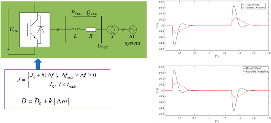
GRAPHICAL ABSTRACT | Focusing on the conventional VSG strategy with fixed control coefficient sacrifices a certain degree of dynamic regulation performance with less robustness, this research proposes an improved VSG strategy with adaptive inertia and damping coefficients to increase the flexibility of VSG.
With the increasingly severe global energy crisis, major countries have shifted their energy acquisition methods from traditional fossil fuels to renewable energy. Wind energy is a kind of clean and environmental-friendly energy (Liu et al., 2023; Zhu et al., 2023). Traditional synchronous generators (TSGs) can provide inertia and damping for the power grid due to the presence of a rotor following disturbances (Liu et al., 2022; Guo et al., 2023; Zhu et al., 2023). Most distributed power generation units are connected to the grid through power electronics. Most of these 31 types of renewable energy generation units are unable to provide inertia and damping as synchronous 32 generators do after a disturbance (Long et al., 2024), thereby resulting in a reduction in spinning reserve capacity and inertia in the power system, particularly for a high renewable energy-integrated power grid (Cheng et al., 2022; Zhou et al., 2023). The power system’s dynamic performance is susceptible to power fluctuations and faults, even leading to instability (Yang et al., 2019). For example, there were two major power outages caused by frequency collapse: in Australia in 2016 and in the United Kingdom in 2019. One of the main reasons for the frequency collapse was the insufficient fault traversal ability of renewable energy and the reduction of system inertia (Björk et al., 2022). Therefore, as the penetration rate of the power electronic equipment increases in a power system, it becomes necessary that power electronic converters can actively provide inertia and damping support capabilities to ensure a stable frequency operation (Cheema, 2020).
Many scholars have suggested the virtual synchronous generator (VSG) strategy to actively provide support capability, which involves upgrading and modifying the control strategy of grid-connected inverters to simulate rotor characteristics (rotational inertia and damping support characteristics) of synchronous generators, so that static inverters also retain damping and rotational inertia support characteristics to the power grid (Hou et al., 2020; Rehman et al., 2021). Thus, it can improve the dynamic support characteristics of inverters and enhance the grid connection ability of grid-connected inverters. This provides a novel research topic for a grid-friendly connection of power generation systems to deal with the issues caused by wind power fluctuations and other disturbances.
Nowadays, although significant progress has been made in the research field of VSG technology, many problems have to be further solved, such as suitable coefficient definition and voltage support. Therefore, many researchers have proposed different improvement control methods of VSGs to enhance the capability of integrating the power grid. Zhong and Weiss (2011) addressed a virtual inertia support strategy for distributed power sources, which can sustain damping and inertia characteristics of a TSG. Zhang et al. (2016) addressed an inertia control strategy that adds a local linearization model of Synchronous generator (SG) in the active frequency droop controller, which can effectively simulate the primary frequency regulation characteristics of the TSG. However, the control coefficient is constant, which sacrifices a certain degree of dynamic regulation performance with less robustness under different operation conditions. Alipoor and Miura (2015) dynamically adjusted the magnitude of inertia in real time based on frequency changes, thereby slowing down rapid frequency changes and improving system frequency stability. However, the influence of damping of the VSG on frequency stability is neglected. Three operating modes for the VSG strategy are addressed to smooth out the frequency fluctuation (Lu et al., 2014). However, it does not provide the value of the moment of inertia and the principle of distinguishing operating modes under the three operating modes. Li et al. (2017) proposed a method for interleaving inertia and damping adaptive control, which has a significant impact on improving system frequency stability. However, the selection principle for damping coefficient was not provided. Thus, the research studies have indicated the feasibility of variable coefficients for VSG. However, the existing strategies of VSG do not provide clear guidelines for determining the control coefficients of inertia and damping control. In addition, using the rate of change of frequency for determining the control coefficient, which is sensitive to the measured frequency, is to easily result in large control coefficients, so as to result in VSG instability.
This article addresses an improved VSG strategy with adaptive damping and inertia coefficients considering system frequency deviations. First, a mathematical model is established to analyze the impact of different control coefficient settings on the characteristics of VSG, and then the root trajectory is used to explore the impact of different rotational inertia and damping coefficients on the stability of the VSG system. Second, an improved control strategy with adaptive inertia and damping coefficients is proposed based on the characteristics of the second-order system and frequency trajectory. Finally, a simulation system embed with VSG is constructed based on MATLAB/Simulink to verify the effectiveness of the addressed strategy with adaptive damping and inertia coefficients under various disturbances.
The organization of the remaining article is as follows: Section 2 introduces a mathematical model of VSG and the impact of different rotational inertia and damping coefficients on the stability of the VSG system based on the root trajectory method. Section 3 proposes an improved control strategy with adaptive inertia and damping coefficients. Section 4 analyzes the effectiveness of the proposed VSG strategy under various disturbances. The conclusion is provided in Section 5.
The VSG strategy not only emulates the characteristics of TSG but also participates in voltage regulation, inertia support, and other control functions, while endowing the static grid-connected inverter with rotational inertia and damping characteristics, so as to enhance its ability to suppress fluctuations (Guo et al., 2023). Figure 1 shows the basic principle topology of the VSG, which consists of two parts: a power control loop and a voltage and current control loop (Qu et al., 2021; Sun et al., 2023). After generating the reference of terminal voltage through the power loop and reference of voltage calculation loop, the corresponding modulation wave is obtained through the voltage and current control loop in the dq coordinate system with the objectives of regulating the power electronic devices on and off. Therefore, it controls the output of the VSG to meet the required voltage and current. Figure 1 shows that P and Q are the active and reactive power outputs of the VSG, respectively; Pref, Qref, and Uref are the reference active power, reactive power, and reference voltage, respectively; and u and e are the output terminal voltage and reference excitation electromotive force, respectively.
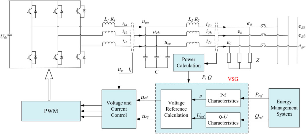
FIGURE 1. Overall control diagram of VSG.
As in Liang et al. (2022), by ignoring the effect of the filtering capacitor C, the relationship between the midpoint voltages of the bridge arm, the terminal voltage, and the inductance current of the VSG is represented as in Eq. 1
where the subscript “abc” represents the component in the abc system.
By using the terminal voltage vector orientation strategy for dq decomposition, the relationship between the voltage and current in the dq coordinate system is
where i1d, i1q, and ud, uq, respectively, are the current and voltage in the dq system of the converter. ucd and ucq, respectively, are the terminal voltage in the dq system. Y and X1 are the impedance matrix and the inductive reactant, respectively, and X1 = ωL1.
The voltage reference value of the bridge arm is used to obtain the terminal voltage command value, which is fed into the voltage and current control loop in the synchronous rotating system. The voltage loop is used to regulate the terminal voltage, and the current loop is controlled by the inductance current ratio on the converter side.
1) To model the VSG strategy, the rotor motion equation is expressed as (Guo et al., 2023)
where D and J are the coefficients of the damping and rotational inertia of the VSG.
Due to the fact that grid-connected inverters do not have the rotational inertia of synchronous generators, they cannot provide inertia support capability. With the integration of large-scale power electronic systems, the inertia of the power system is gradually decreasing, thereby affecting the stable operation of the power system. Therefore, to address this issue, the control inverter is modified and provides the damping and inertia support to the grid (Li et al., 2023; Yang et al., 2023). The rotor equation of the VSG strategy is the same as Eq. 5, while the control block diagram is illustrated in Figure 2.
2) VSG could regulate the reactive power by emulating the excitation regulation effect of TSG and 130 constructs a virtual excitation controller (Du et al., 2021). This relationship is given as in Eq. 6.
where Kq and Ku are the coefficients of the reactive-voltage droop and voltage regulation, respectively.
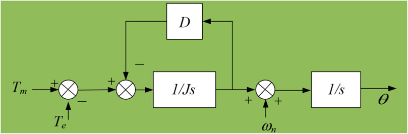
FIGURE 2. Diagram of VSG control strategy.
The damping and rotational inertia coefficients are the core variables in the VSG control system. However, the rotational inertia of SG only depends on the physical characteristics of the internal rotor and is generally constant; the rotational inertia of the VSG is a virtual value that is not constrained by the system, thus its value is relatively flexible and can be designed on the basis of the control objectives.
As shown in Figure 2, the active and reactive powers injected to the electric power system can be expressed as in Eq. 7 and Eq. 8
where φ and θ are the power angle and impedance angle of the VSG, respectively.
The inductive component of the line impedance (Xs) in high-voltage and medium-voltage power transmission is usually much higher than the resistive component (Rs). Therefore, the resistive part of line impedance is ignored. Thus, Pe can be re-expressed as (Sun et al., 2023)
When the VSG is connected to the power grid, its frequency is constrained by the grid. Drawing on the small-signal model analysis method of SG, the closed-loop transfer function of the active power control loop for VSG is calculated as
Equation 10 is represented as a typical second-order transfer function system form. The damping ratio and natural oscillation angular frequency are given as in Eq. 11
According to the theory of automatic control, adjusting the time ts and overshoot σ% is important for the dynamic performance of the system. The performances of the second-order system shown in Eq. 10 are dependent on the setting of the coefficient for D and J. When D is constant, the use of a larger J results in a smaller ξ, larger overshoot σ%, and a longer adjustment time ts. When J is constant, the use of a larger D would result in a larger ξ, smaller overshoot σ%, and smaller ts. Thus, the oscillation frequency is determined by the setting of the coefficient for J, while the setting of D determines the oscillation attenuation rate of the active power response.
To analyze the effect of the setting of D and J on system stability of the VSG, the linearized Eq. 5 would derive the active-power small-signal model of the VSG power controller:
According to Eq. 12, a small-signal model of the VSG power controller in the s domain can be drawn, as shown in Figure 3. The closed-loop characteristic equation of the active power response is obtained as
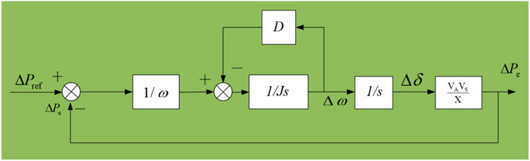
FIGURE 3. Small-signal model of VSG.
The various settings of J and D provide an impact on the stability of the VSG. Figure 4 shows the root trajectory with different settings of J and D based on Eq. 13. Obviously, the use of a larger D results in a reduction of the absolute value of the real part, leading to the rapid decay rate and short adjusting period. From Figure 4B, it can be seen that if D is constant, the use of a larger J leads to the open-loop poles being closer to the coordinate origin, which in turn deteriorates the system’s stability. Hence, the coefficient of rotational inertia cannot be a large value. Meanwhile, the large setting of D is beneficial for improving the stability of the VSG. Thus, the setting limitations of D and J can be derived based on the stability analysis.
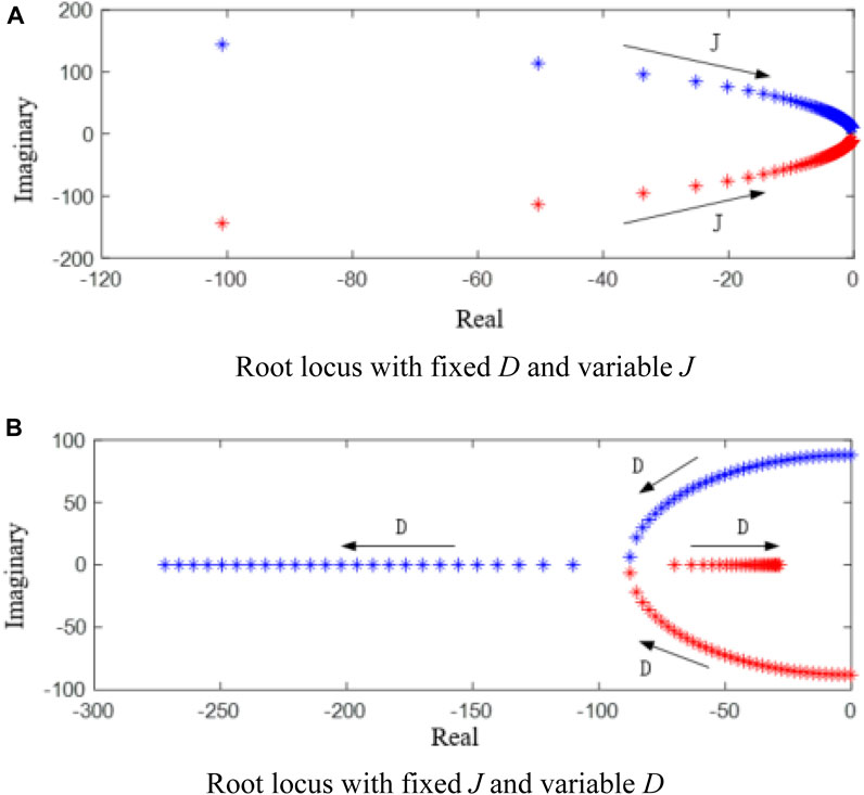
FIGURE 4. Root locus with different coefficients of VSG.
Figure 5 shows the system frequency trajectory following a disturbance. During the initial period of disturbance, the change of frequency depends on the moment of inertia of the power system, after that the system frequency deviation becomes large and more attention should be paid so as to arrest the frequency decline. According to the frequency trajectory, the definition of adaptive J can be defined in two parts: the first part is before the frequency nadir and the second part is after the maximum frequency deviation, as shown in Eq. 14. To arrest the frequency deviation, the adaptive D can be designed as in Eq. 15, which only contains one part, with the objective of improving the frequency deviation. Figures 6, 7 show the first part of the control coefficient of inertia and the droop control coefficient, respectively. In Figure 6, the coefficient of J increases as the frequency deviation increases, with the objective of reducing the imbalance power and arresting the frequency decline. In Figure 7, the coefficient of damping increases as the frequency deviation increases, with the aim of reducing the maximum frequency deviation. In addition, the rate shown in Figure 6 and Figure 7 depends on the setting of the regulating factor and the frequency deviation. Figure 8 shows the control diagram of the proposed scheme.
where J0 and D0 are the initial values of inertia and the damping control loop and are defined by considering the characteristics of the typical second-order transfer function system. Δf, Δfmax, and tnadir are the frequency deviation, maximum frequency deviation, and occurrence time of the maximum frequency deviation, respectively. k and b are the controllable coefficients of damping and inertia coefficients, respectively. In this article, b and k are restricted by considering the stability of the VSG. Thus, the proposed adaptive coefficient would improve the frequency support capability while avoiding instability of the VSG.
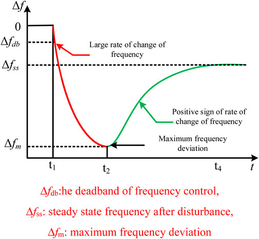
FIGURE 5. System frequency trajectory following a disturbance.
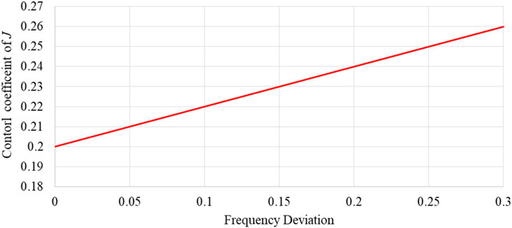
FIGURE 6. First part of control coefficient J.
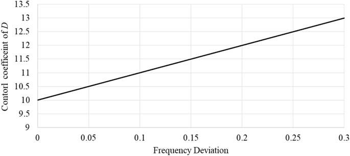
FIGURE 7. Control coefficient D.
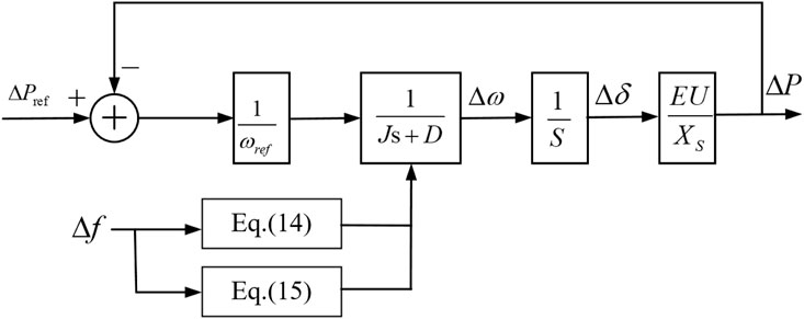
FIGURE 8. Control diagram of the proposed scheme.
Since the rate of change is greatly affected by noise, which can easily cause sudden changes in control gain, the rate of change of frequency would not be considered to define the adaptive control coefficient of J and D control loops. As in Eqs 14, 15, the frequency deviation is employed to adjust the control coefficient of J and D. In Eq. 14, the control coefficient J linearly increases with the frequency deviation to reduce the imbalance power and starts from 0.2, which is the initial value. As the frequency deviation increases, the control coefficient of J increases until the maximum frequency deviation is captured. After the maximum frequency deviation, the coefficient of J decreases to J0 to avoid the negative impacts on frequency rebounding. In Eq. 15, the control coefficient increases with the frequency deviation so as to decrease the maximum frequency deviation.
To ensure the occurrence time of the maximum frequency deviation, the frequency deviation detector is used. As in Eqs 16, 17, if the frequency deviation is less than the absolute value of 0.001 Hz while the rate of change of frequency is less than 0.01 Hz/s, it means that tnadir is captured.
Once the thresholds in Eqs 16, 17 are met, it means that the frequency nadir is detected and tnadir would be marked. This approach might detect the frequency nadir slightly later or earlier than the actual frequency nadir. However, it does not have a severe impact on the frequency support capability since the output power of the VSG would change excessively.
Figure 9 shows the flowchart of the proposed VSG strategy with adaptive control coefficient. The frequency deviation is measured to calculate the control coefficient of J and D depending on Eqs 14, 15. Meanwhile, the frequency deviation and rate of change of frequency are calculated, which is used to switch the calculation for the second part of J. In addition, the calculated J and D are restricted to the upper limits of causing instability of the VSG.
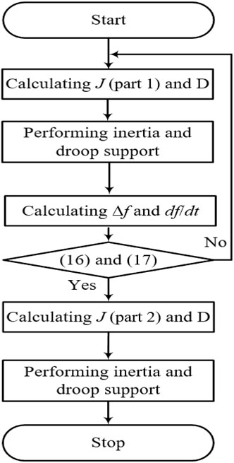
FIGURE 9. Flowchart for the proposed VSG scheme.
This article suggests an improved VSG strategy with adaptive inertia and damping coefficients. Such coefficients are defined in Eqs 14, 15 and are restricted by the derived limitation based on stability. As the frequency deviation increases, the control coefficients become large to increase the flexibility of VSG so as to improve the frequency support capability. In addition, for the coefficient of inertia, it changes to the initial value when the frequency nadir is detected to avoid the neglected impact on the frequency rebounding period.
To indicate the effectiveness of the addressed VSG strategy with adaptive control coefficients, a model embedded with a VSG is built in MATLAB/Simulink, as shown in Figure 10. Table 1 shows the parameters for simulation. The reactive power and active power of the load is set to 2 kvar and 12 kW, respectively. The initial operating condition of the VSG is 2 kW. As a disturbance, at 0.5 s, the active power of the VSG suddenly increases and then decreases after 0.8 s for Case 1 and Case 2, and the active power of the VSG suddenly decreases and then increases after 0.8 s for Case 3 and Case 4. In the simulation results, J fixed and D fixed mean that the VSG with fixed inertia and damping coefficients are employed. In addition, J variable and D variable mean that the adaptive inertia and damping coefficient are employed in the VSG.
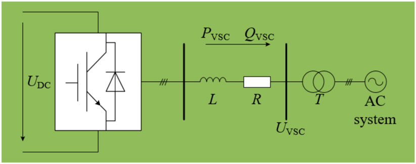
FIGURE 10. Simulation model of VSG connected to the AC system.
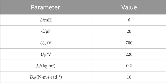
TABLE 1. Parameters of the simulation model.
Figure 11 shows the step response curves of the output active power of the VSG under the different control coefficients of damping and inertia control of the VSG. During the initial period of disturbance, compared with using a constant J strategy, using a variable J strategy can effectively suppress frequency decrease. As the frequency deviation increases, using a variable damping coefficient strategy can reduce the frequency deviation. At the same time, when using an excessively large J strategy, it will generate a large overshoot.
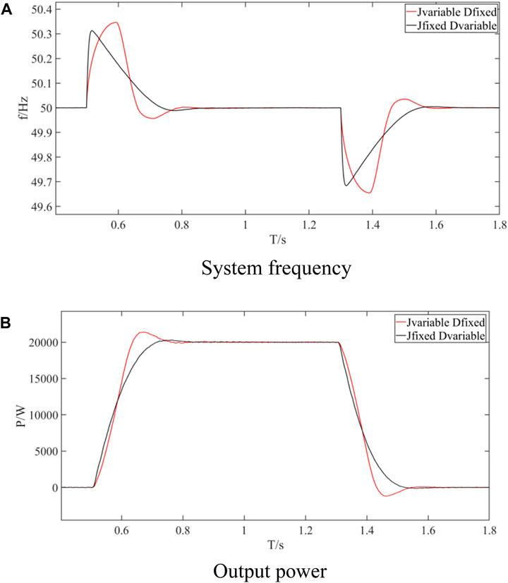
FIGURE 11. Comparison results with various control coefficients for Case 1.
Figure 12 shows the comparison results of system frequency and VSG output under different control coefficients of damping and inertia control of the VSG for Case 2. As shown in Figure 12A, at 0.5 s, the active power of the VSG suddenly increases to 12 kW, and the maximum frequency deviation of the VSG under fixed control parameters is 0.632 Hz. When using the adaptive coefficients of damping and inertia, the maximum frequency deviation reduces to 0.222 Hz. When the power suddenly drops, the maximum frequency deviation of the VSG under fixed control parameters is 0.633 Hz. When using an improved VSG strategy with adaptive damping and inertia coefficients, the maximum frequency deviation reduces to 0.221 Hz. Figures 12C, D show the changes in J and D. The adaptive change of the coefficients of damping and inertia based on the frequency deviation has a significant impact on the maximum frequency deviation and df/dt so as to smooth out the out fluctuation of VSG outputs, thereby effectively improving the grid connection ability of the VSG.
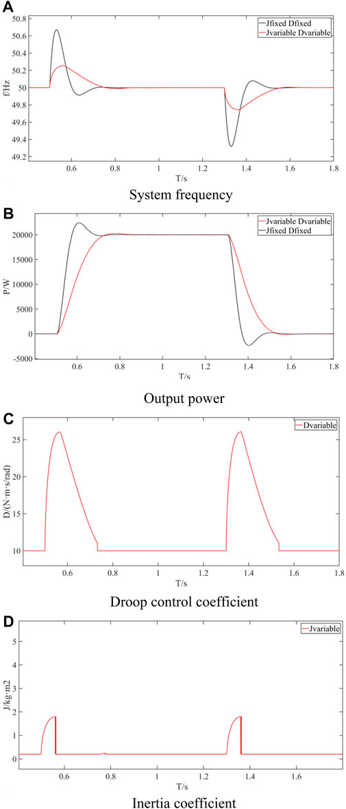
FIGURE 12. Comparison results with various control strategies for Case 2.
Figure 13 shows the comparison results of system frequency and VSG output under different control coefficients of damping and inertia control of the VSG for Case 3. Similar to Case 1, during the initial period of disturbance, compared with using a constant J strategy, the VSG employs a variable J strategy that could effectively suppress frequency decline. With the increasing frequency deviation, the VSG using a variable damping coefficient can decrease the frequency deviation. In addition, when the VSG uses an excessively large J strategy, a large overshoot would be caused.
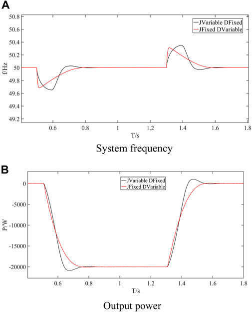
FIGURE 13. Comparison results with various control strategies for Case 3.
Figure 14 shows the comparison results of system frequency and VSG output under different control coefficients of damping and inertia control of the VSG for Case 4. At 0.5 s, the active power of the VSG suddenly decreases and then the output power is suddenly recovered at 1.5 s, which is the inverse disturbance to Case 2. During the first disturbance, the maximum frequency deviation of the VSG under fixed control parameters is 0.68 Hz. When the VSG uses the adaptive coefficients of damping and inertia, the maximum frequency deviation reduces to 0.26 Hz. During the second disturbance, the maximum frequency deviation of the VSG under fixed control parameters is 0.67 Hz. When the VSG uses an improved VSG strategy with adaptive damping and inertia coefficients, the maximum frequency deviation reduces to 0.26 Hz. The adaptive variation of coefficients for damping and inertia control has a significant impact on the maximum frequency deviation and df/dt so as to smooth out the fluctuation of VSG outputs, thereby effectively improving the grid connection ability of the VSG.
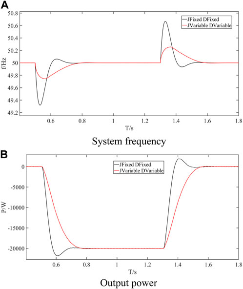
FIGURE 14. Comparison results with various control strategies for Case 4.
Under various operations of the VSG, the inertia and damping support capabilities are different, and the conventional VSG strategy with fixed control coefficients sacrifices a certain degree of dynamic regulation performance with less robustness. This article addresses an improved VSG strategy with adaptive damping and inertia coefficients considering the system frequency deviations and stability of the VSG. The conclusions are as follows: 1) a mathematical model is established to analyze the impact of various parameters on the characteristics of the VSG, and then the root trajectory is used to explore the impact of different rotational inertia and damping coefficients on the stability of the VSG system. In addition, the oscillation frequency is dependent on the setting of inertia during which the setting of D determines the oscillation attenuation rate of the active power response. 2) When compared with the conventional fixed coefficient, the VSG control strategy, the proposed control strategy can reduce the maximum frequency deviation and increase the robustness of the VSG, thereby improving the integrating capability of the VSG under various over-frequency and under-frequency disturbances. Thus, the addressed adaptive control coefficient would enhance the system frequency regulating capability while avoiding the instability of the VSG. In the future, multi-VSGs are to be considered for designing the coordinating inertia and damping control strategy.
The raw data supporting the conclusion of this article will be made available by the authors, without undue reservation.
DL: Investigation, Software, Writing–original draft. KJ: Investigation, Methodology, Writing–original draft. XJ: Investigation, Writing–original draft. KC: Writing–original draft. CX: Writing–original draft. SS: Funding acquisition, Methodology, Writing–review and editing. DY: Writing–original draft.
The author(s) declare financial support was received for the research, authorship, and/or publication of this article. This work was partially supported by the Science and Technology Project of State Grid Hubei Electric Power Co., Ltd. (52153223001N), and partially supported by the National Natural Science Foundation of China (52307208).
The authors declare that the research was conducted in the absence of any commercial or financial relationships that could be construed as a potential conflict of interest.
All claims expressed in this article are solely those of the authors and do not necessarily represent those of their affiliated organizations, or those of the publisher, editors, and reviewers. Any product that may be evaluated in this article, or claim that may be made by its manufacturer, is not guaranteed or endorsed by the publisher.
Alipoor, J., and Miura, Y. (2015). Power system stabilization using virtual synchronous generator with alternating moment of inertia. IEEE J. Emerg. Sel. Top. Power Electron. 3 (2), 451–458. doi:10.1109/jestpe.2014.2362530
Björk, J., Pombo, D. V., and Johansson, K. H. (2022). Variable-speed wind turbine control designed for coordinated fast frequency reserves. IEEE Trans. Power Syst. 37 (2), 1471–1481. doi:10.1109/tpwrs.2021.3104905
Cheema, K. M. (2020). A comprehensive review of virtual synchronous generator. Int. J. Electr. Power and Energy Syst. 120, 106006. doi:10.1016/j.ijepes.2020.106006
Cheng, Z., Li, H., Zhou, Y., Lv, Y., and Chen, J. (2022). Virtual synchronous generator of PV generation without energy storage for frequency support in autonomous microgrid. Int. J. Electr. Power and Energy Syst. 134, 107343. doi:10.1016/j.ijepes.2021.107343
Du, W., Dong, W., Wang, Y., and Wang, H. (2021). Small-disturbance stability of a wind farm with virtual synchronous generators under the condition of weak grid connection. IEEE Trans. Power Syst. 36 (6), 5500–5511. doi:10.1109/tpwrs.2021.3080700
Guo, F., Yu, J., Ni, Q., Zhang, Z., Meng, J., and Wang, Y. (2023b). Grid-forming control strategy for PMSG wind turbines connected to the low-frequency AC transmission system. Energy Rep. 9, 1464–1472. doi:10.1016/j.egyr.2022.12.083
Guo, X., Zhu, D., Hu, J., Zou, X., Kang, Y., and Guerrero, J. M. (2023a). Inertial PLL of grid-connected converter for fast frequency support. CSEE J. Power Energy Syst. 9 (4), 1594–1599. doi:10.17775/CSEEJPES.2021.08650
Hou, X., Sun, Y., Zhang, X., Lu, J., Wang, P., and Guerrero, J. M. (2020). Improvement of frequency regulation in VSG-based AC microgrid via adaptive virtual inertia. IEEE Trans. Power Electron. 35, 1589–1602. doi:10.1109/tpel.2019.2923734
Li, C., Yang, Y., Cao, Y., Aleshina, A., Xu, J., and Blaabjerg, F. (2023). Grid inertia and damping support enabled by proposed virtual inductance control for grid-forming virtual synchronous generator. IEEE Trans. Power Electron. 38 (1), 294–303. doi:10.1109/tpel.2022.3203049
Liang, S., Jin, S., and Shi, L. (2022). Research on control strategy of grid-connected brushless doubly-fed wind power system based on virtual synchronous generator control. CES Trans. Electr. Mach. Syst. 6 (4), 404–412. doi:10.30941/cestems.2022.00052
Li, D., Zhu, Q., Cheng, Y., et al. (2017). Control strategy of virtual synchronous generator based on self-adaptive rotor inertia and damping combination control algorithm. Electr. Power Autom. Equip. 37 (11), 72–77.
Liu, Y., Wang, Y., Liu, X., Wang, M., Xu, Z., and Liu, H. (2023). Steady-state angle stability analysis of parallel grid-forming converters in current saturation mode. IEEE Trans. Power Electron. 38 (7), 8039–8044. doi:10.1109/tpel.2023.3267624
Liu, Y., Wang, Y., Wang, M., Xu, Z., Peng, Y., and Li, M. (2022). Coordinated VSG control of photovoltaic/battery system for maximum power output and grid supporting. IEEE J. Emerg. Sel. Top. Circuits Syst. 12 (1), 301–309. doi:10.1109/jetcas.2022.3143716
Long, BO, Yang, W., Zhu, S., Guerrero, J. M., Rodríguez, J., et al. (2024). Power-frequency admittance model of multi-VSGs grid-connected system considering power coupling. Int. J. Electr. Power and Energy Syst. 155, 109513. Part A. doi:10.1016/j.ijepes.2023.109513
Lu, Z., Sheng, W., Zhong, Q., et al. (2014). Virtual synchronous generator and its applications in micro-grid. Proc. CSEE 34 (16), 2591–2603.
Qu, Z., Peng, C. H., Yang, H., and Srinivasan, D. (2021). Modeling and analysis of inner controls effects on damping and synchronizing torque components in VSG-controlled converter. IEEE Trans. Energy Convers. 36 (1), 488–499. doi:10.1109/tec.2020.3010049
Rehman, H. U., Yan, X., Abdelbaky, M. A., Ullah Jan, M., and Iqbal, S. (2021). An advanced virtual synchronous generator control technique for frequency regulation of grid-connected PV system. Int. J. Electr. Power Energy Syst. 125, 106440. doi:10.1016/j.ijepes.2020.106440
Sun, P., Xu, H., Yao, J., Chi, Y., Huang, S., and Cao, J. (2023). Dynamic interaction analysis and damping control strategy of hybrid system with grid-forming and grid-following control modes. IEEE Trans. Energy Convers. 38 (3), 1639–1649. doi:10.1109/tec.2023.3249965
Yang, D., Wang, X., Chen, W., Jin, Z., Jin, E., et al. (2023). Adaptive frequency droop feedback control-based power tracking operation of a DFIG for temporary frequency regulation. IEEE Trans. Power Syst., 1–10. doi:10.1109/TPWRS.2023.3277009
Yang, Y., Mei, F., Zhang, C., et al. (2019). Coordinated adaptive control strategy of rotational inertia and damping coefficient for virtual synchronous generator. Electr. Power Autom. Equip. 39 (3), 125–131.
Zhang, Y., Zhu, M., Zhang, J., et al. (2016). Control strategy of virtual synchronous generator based on adaptive adjusting for distributed inverters. J. Power Supply 14 (3), 11–19.
Zhong, Q., and Weiss, G. (2011). Synchronverters: inverters that mimic synchronous generators. IEEE Trans. Industrial Electron. 58 (4), 1259–1267. doi:10.1109/tie.2010.2048839
Zhou, YI, Cao, J., and Zhao, J. (2023). Small-signal oscillatory stability of a grid-connected PV power generation farm affected by the increasing number of inverters in daisy-chain connection. Front. Energy Res. 10, 2023. doi:10.3389/fenrg.2022.1022060
Keywords: grid-forming inverter, VSG, inertia and damping, frequency deviation, adaptive control coefficient
Citation: Liu D, Jiang K, Ji X, Cao K, Xu C, Sang S and Yang D (2024) Improved VSG strategy of grid-forming inverters for supporting inertia and damping. Front. Energy Res. 11:1331024. doi: 10.3389/fenrg.2023.1331024
Received: 31 October 2023; Accepted: 15 December 2023;
Published: 11 January 2024.
Edited by:
Liansong Xiong, Xi’an Jiaotong University, ChinaReviewed by:
Donghai Zhu, Huazhong University of Science and Technology, ChinaCopyright © 2024 Liu, Jiang, Ji, Cao, Xu, Sang and Yang. This is an open-access article distributed under the terms of the Creative Commons Attribution License (CC BY). The use, distribution or reproduction in other forums is permitted, provided the original author(s) and the copyright owner(s) are credited and that the original publication in this journal is cited, in accordance with accepted academic practice. No use, distribution or reproduction is permitted which does not comply with these terms.
*Correspondence: Shun Sang, shunsang@ntu.edu.cn
Disclaimer: All claims expressed in this article are solely those of the authors and do not necessarily represent those of their affiliated organizations, or those of the publisher, the editors and the reviewers. Any product that may be evaluated in this article or claim that may be made by its manufacturer is not guaranteed or endorsed by the publisher.
Research integrity at Frontiers
Learn more about the work of our research integrity team to safeguard the quality of each article we publish.