 Pan Hu
 Kezhen Jiang1
- 1State Grid Hubei Electric Power Research Institute, Wuhan, China
- 2State Grid Hubei Electric Power Company Limited, Wuhan, China
The demand for decarbonization calls for nearly 100% renewable electricity rising as the dominant power resource. The foregoing paradigm shifts require proactive voltage and frequency controllers for the converter-based renewable energy. This article proposed a novel grid-forming technique for voltage-source controlled photovoltaic (PV) operating in 100% renewable power systems. The proposed idea was to design a DC voltage collapse-prevention controller in conjunction with a simplified frequency and inertia controller, thereby smart capturing and releasing PV energy to achieve improvements in dynamic performance and efficiency. By setting the two-phase operation scheme, the model initiatively considers the conflict between frequency regulation and maximum power point tracking (MPPT) curve control. The preferred controls are validated using extensive simulation and experimental findings based on a semi-physical platform and a practical photovoltaic demonstration project. The proposed controller outperforms the standard PV current controller over a much larger range of weak grid situations, according to the experimental and engineering operational data. Results demonstrated the effectiveness of the presented method in applying to the future 100% renewable power system.
1 Introduction
Growing promises to reduce greenhouse gas emissions, as well as ambitious endeavors to minimize global average temperature rise, have driven efforts to decarbonize electricity, with a special emphasis on the use of renewable energy resources (Wu et al., 2021). The climate action plan necessitates the development of a nearly 100% renewable energy system and hence focuses on meeting the operation challenge of the uncertain nature of resources, primarily wind and solar PV. With RE becoming a prominent source in the system, the inverter-based or non-synchronous interface with the grid requires a proactive control strategy undertaking voltage and frequency regulation and support. Furthermore, grid-forming resources need to be widely used to improve synchronization stability in 100% renewable systems or weak grids (Blakers et al., 2019).
There, so far, mainly exists two types of inverter-based resources, i.e., the controlled current (CC) and the controlled voltage (CV) renewable sources (Fu et al., 2021). The CC type uses a phase-locked loop (PLL) to track the voltage and frequency at the point of common coupling (PCC) (Li et al., 2018; Zhou et al., 2018). Moreover, the CC interface often introduces voltage feed-forward (VFF) control to achieve improvement in dynamic response and harmonics suppression, which is particularly appropriate for connecting to a strong grid. But at high penetration of RE, i.e., weak grid conditions, the CC controller also causes wide-frequency oscillation, causing harmonic resonance and system instability (Dong et al., 2015). With grid impedance fluctuation, the use of a VFF controller led to the positive feedback of grid impedance, resulting in injecting the harmonic current into weak grids and triggering a tendency toward progressive system instability. In addition, the PLL controller negatively affects the stability of CC inverters under weak grids. Xu et al. (2019) point out that the time delay in PLL brings a negative damping phenomenon, resulting in inverter oscillation. Meanwhile, in weak grids, the PLL bandwidth causes harmonic resonance. With the increase in bandwidth, the damping of the inverter impedance in the low-frequency band deteriorated (Silwal et al., 2019). Through the introduction of improved controllers, for example, time-delay compensation (Zhang et al., 2018), impedance reshaping (Fang et al., 2018a), and adaptive gain scheme (Xu et al., 2017), mitigates the preceding concerns; the dynamic performance of the CC interface is debased. In case of large transient disturbances, some CC renewable sources lose stable equilibrium points and synchronization stability (He et al., 2020). In light of the aforementioned drawbacks, CC resources are better suited for use in strong power systems.
For weak grids, especially under nearly 100% renewable electricity, the CV interface is proven to be a better solution than the CC interface. As a typical grid-forming resource, the CV types achieve power output directly by controlling the voltage vector phase and amplitude, enabling CV to be inherently synchronized with the grid without applying PLL (Yuan et al., 2009). CV resources proactively provide frequency and voltage modulation and moment of inertia if a virtual synchronous generator (VSG) is introduced (Zhong and Weiss, 2011). Furthermore, grid damping and impedance characteristics are increased without compromising CV interface dynamic performance under a lower short current ratio (SCR) (Wu et al., 2019). Therefore, the CV resources are thought to be an efficient solution and a significant component in the configuration of 100 percent renewable systems (Wang et al., 2020; Sang et al., 2022). To satisfy the CV interface requirement, renewable resources typically add energy storage equipment into their DC side to counteract energy absorption or release in the dynamic regulation process, i.e., the unpredictability of wind and solar power (Liu et al., 2021). The energy storage handles the fast-varying power generated by inertia simulation through VSG control, whereas PV implements the portions of frequency regulation and adjusts for relatively long-term power variations with sluggish dynamics. As a result, the VSG provides a better dynamic frequency response during power fluctuations (Fang et al., 2018b; Debnath et al., 2021). To manage PV and energy storage resources, the integrated development combines enhanced control methods to offer inertial and main frequency response, reactive power support, and transient stability (Zhong and Weiss, 2011; Liu et al., 2021). However, virtual synchronous control often treats the DC side as the ideal source and ignores the energy storage limitation; it is difficult to apply it directly to RE’s self-synchronous voltage source control. Moreover, because of the energy storage (ES), the traditional VSG technique is difficult to apply in a practical wind turbine and PV unit. ES increases the operation and maintenance workload after installation. The occupied space, geographical location, and machine requirements in the primary component of the original CC equipment restrict the application of ES and hence increase the potential challenges of CV sources used for wind turbines and PV (Imai et al., 2018). Therefore, a proposal for a grid-forming plan for each RE unit without the addition of energy storage is both promising and necessary. However, not much work deals with the above-mentioned relevant issues. This is mostly due to a clash between the uncertainty of RE output and the need for constant frequency support. The MPPT approach, for instance, is responsible for the output of PV arrays. The MPPT controller in the PV needs to be changed to set commands that absorb or release energy in accordance with the primary frequency control requirement. Therefore, the CV interface has the potential to cause PV DC voltage collapse, posing a threat to the PV safety and stability (Hua et al., 2017).
Inspiring by the aforementioned works, this article strived to carry out a novel grid-forming strategy for voltage-source controlled PV without adding energy storage. Thus, the proposed planning model provides a novel perspective of flexibility to operate with nearly 100% renewable electricity. The main contribution and novelty of our works settle in:
1) The article developed a DC voltage collapse-prevention controller that works in tandem with a simpler frequency and inertia controller to capture and release PV energy intelligently. The model resolves the issue between frequency regulation and the MPPT approach by establishing the time accounting-storage strategy. The suggested control algorithm can offer adequate actual and reactive power services, as well as ensure PV DC voltage stability, under dynamic system operation and atmospheric circumstances, according to simulation findings obtained during system disruptions and rapid solar irradiation variations.
2) A CV interface and controller framework for the PV is proposed without including energy storage, combined with the proposed model established by the DC voltage collapse-prevention controller and time accounting-storage method. By offering voltage and frequency control and supporting a weak grid, the unique grid-forming technique provides a perspective of flexibility to function in nearly 100% renewable electricity and an ability to design a weak grid.
The article is organized in the manner as follows. Section 2 theoretically presents the main idea of DC voltage collapse prevention and gives the controller model. Subsequently, the CV interface and controller framework are put forward in Section 3. Section 4 is devoted to the simulation and hardware-in-the-loop (HIL) experiments and practical engineering verification. Conclusions and future works are summarized in section 5.
2 Control Strategy and System Design
2.1 Stable Operation Area of MPPT
To clearly analyze the stable operation area of MPPT and DC voltage stability, the following assumptions are put forward:
Assumption 1. The load is less than the PV array’s maximum output power.
Assumption 2. The modulation ratio m of the PV inverter is sufficient.As shown in Figure 1, the P-V curves indicate the following: 1) when
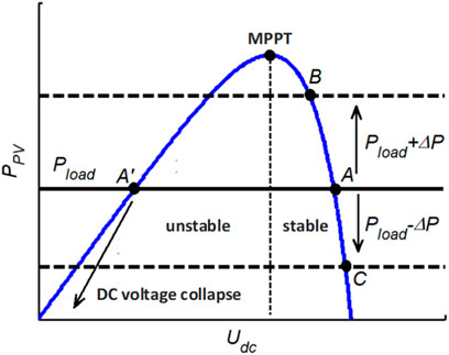
FIGURE 1. P-V curves of the photovoltaic array.
2.2 DC Voltage Collapse-Prevention Controller
Based on previous analysis, the DC voltage crosses the MPPT point into the unstable region, causing the DC bus voltage to collapse when the PV unit is overloaded. Affected by the variation in the luminous intensity, the maximum DC voltage and MPPT points vary simultaneously. The evolving MPPT curve makes determining the maximum Pmax in time difficult, and if Pmax exceeds the MPPT maximum power point, a DC voltage collapse occurs. If the DC voltage can be regulated directly during PV overload, it is envisaged that DC voltage collapse can be prevented.
The diagram of the DC voltage collapse-prevention controller is given in the Figure 2 a follows:
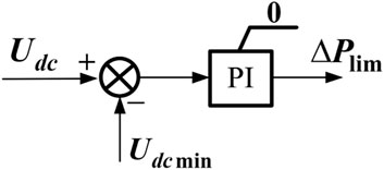
FIGURE 2. DC voltage collapse-prevention controller.
The controller is a PI controller with an upper limit of 0.
The principal frequency and inertia response can be met by reserving MPPT power, according to the aforementioned DC voltage collapse-prevention controller. However, due to the photoperiodic effect and the uncertainty of solar radiation, multiple MPPT curves exist, shown as in Figure 3. As a result, as solar radiation changes, the maximum power and lowest
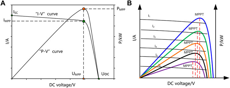
FIGURE 3. Characteristic of multiple MPPT curves: (A) Typical P-V and I-V curves. (B) Multiple P-V curves of PV.
This article designed a two-phase operation scheme for CV PV sources: the start-up phase and the frequency regulation phase.
Start-up phase: After reaching the maximum power point, the controller enters the MPPT state first, starts the MPPT algorithm, and records the power and DC voltage.
Frequency regulation (FM) phase: The PV seamlessly switches from the MPPT state to FM state and closes the MPPT at the same time. After leaving the maximum power with a specified reserve
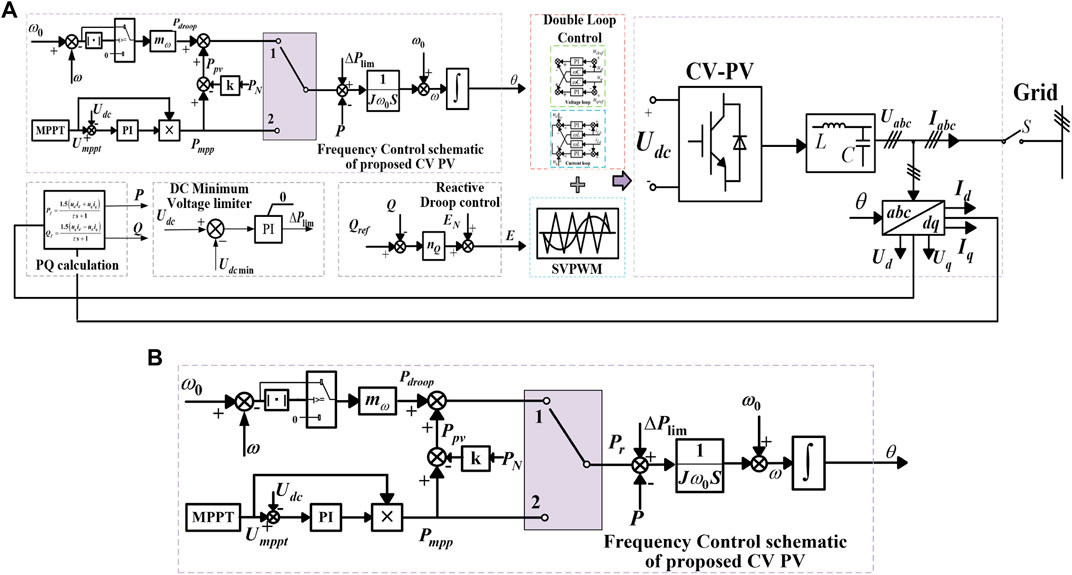
FIGURE 4. Structure of the grid-forming controller with the DC voltage collapse-prevention controller. (A) Overall schematic controller of proposed CV-PV; (B) proposed frequency controller combined with DC voltage collapse-prevention controller.
2.3 Grid-forming Strategy for Voltage-Source Controlled PV
To clearly illustrate the main controller of the CV-PV, the overall schematic is shown in Figure 4A. Frequency and reactive controller, double loop and PWM module and power calculation, electrical measurement, and transformation module are the four basic components. The overall schematic controller takes advantage of the aforementioned technique paired with the proposed DC voltage collapse prevention by using a typical double closed-loop structure (Sun et al., 2021),
To test the proposed approach and calculate the PI and inertia parameters, Fu et al. (2021) introduced a small signal stability model. This is a summary of our earlier grid-forming controller work. The approach for detailed modeling can be found in the corresponding article. Figure 5 shows the model’s main parameters and the model findings, i.e., characteristic root and eigenvalue curves.
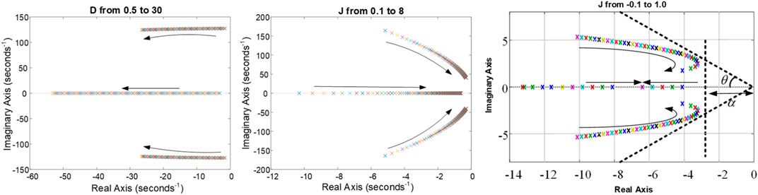
FIGURE 5. Characteristic root and eigenvalue curves of the CV-PV controller.
3 Case Study and Analysis
Three scenarios, based on a semi-physical platform and a practical photovoltaic demonstration project, are used to validate the suggested technique through comprehensive simulation and experimental data. The first example is an RT-LAB-based PV station simulation in Hubei, China. The purpose of this case was to analyze the controller’s validity and dynamic characteristics for a PV station, as well as to optimize the parameters of these units under various circumstances. The PV station’s hardware in-the-loop (HIL) tests with a CV-PV controller are then carried out in Case 2. As shown in the following figure, the EMT Hardware Solver (eHS) circuit of this PV is constructed in the RT-LAB platform, and the control component is accomplished by using a realistic DSP digital controller of SG500MX-V6, i.e., a 500 kW PV from Sungrow Company. The dynamic frequency response and voltage supporting findings are presented to illustrate the differences between the prior and optimal strategies for improving the PV’s operation characteristics and resilience. The recording data and construction information of an actual PV engineering project are provided in Case 3. This project is the power side construction part of the 100% renewable energy demonstration project in Suizhou, Hubei Province, China. About 32 MW PV will be updated and reformed to CV-PV. The findings of this study have already been implemented in engineering practice. The engineering data’s detailed results demonstrated the practicality of the proposed solution in a large-scale renewable project. In all cases, the CV-PV controller’s stability and dependability validated the proposed strategy.
3.1 Case 1
An independent grid simulation model consisting of CV-PV is developed in RT-LAB/Simulink to verify the effectiveness of the controller technique, as shown in Figure 6. The parameters of this controller are given in the following Table 1. This test is a stand-alone system that consists of three parts: the grid part, the equivalent transmission line, and the tested equipment, of which
1) The grid part is built with the ideal voltage source model, and the power disturbance and fault ride-through configuration are completed by directly scaling the voltage source.
2) The analogous transmission line is designed inductively, with inductance used to represent the transformer and other equipment in the transmission line above the equipment under test, and the short-circuit ratio is set to 1.5.
3) The proposed CV-PV inverter is used in the test equipment. Its dynamic characteristics of transient and steady response are used to determine the effectiveness of the control strategy.
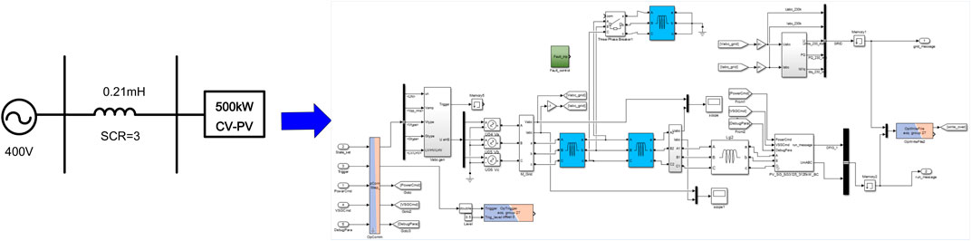
FIGURE 6. Test platform of the CV-PV controller under RT-LAB/Simulink.
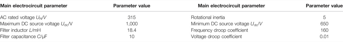
TABLE 1. Case scenario description.
The simulation timer is set to 5 sec. The initial local load is PL = 400 kW and QL = 20 kVar; the load is increased to PL = 420 kW and QL = 25 kVar at 1 s and returns to the initial value at 2 s; the load is reduced to PL = 380 kW and QL = 10 kVar at 3 s and returns to the initial value at 4 s; the load is reduced to PL = 380 kW and QL = 10 kVar at 3 s and returns. Figure 7A shows how the virtual proposed control approach compares to the traditional droop control strategy in terms of dynamic response curves of frequency under unexpected load changes. Low-voltage ride-through (LVRT) testing is performed on the voltage source inverter, in which the fault ride-through mimics balanced and unbalanced tests under 20% voltage dips. The inverter’s steady-state working condition is set to 100% Pn for the duration of the test. Figure 7B shows the simulation results.
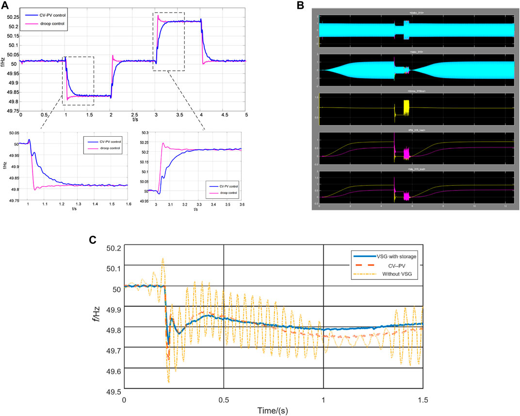
FIGURE 7. Simulation results of the CV-PV controller. (A) Dynamic response curves of frequency under unexpected load changes, (B) LVRT test on voltage source inverter, and (C) dynamic comparison of the traditional CC controller, VSG with energy storage, and proposed CV-PV.
In Figure 7C, the comparison of the traditional CC controller, VSG with energy storage, and proposed CV-PV in frequency dynamic response is given. The setting of the simulation condition is the same as in Figure 7A, i.e., 20 kW active power disturbance is introduced. The results revealed that the proposed controller has a good behavior as traditional VSG with energy storage. As displayed in Figure 7, the system state does not lose stability in both power disturbance and transient periods. Obviously, the simulation results revealed that compared to the droop control, the control algorithm described in this research has a smoother frequency control impact, and its inertia features save time for future frequency regulation.
3.2 Case 2
In this scenario, HIL tests using grid-connected CV-PV are carried out. In Figure 8A, the controller circuit and the eHS model of the primary hardware element of the 500 kW PV are shown, respectively. Two 500 kW PVs comprise a 1 MVA generation unit, as shown in Figure 8A, and power is transferred between them via a boosting transformer with split winding. The circulation current between CV-PV is generally limited due to the high impedance between split windings, especially when using the virtual impedance technique. The HIL experiments are carried out using this practical unit, and its platform is depicted in Figure 8B. The inverter control section of the DSP control board is primarily responsible for the output control signal. The metering board is primarily in charge of communicating with the touch screen. The transmission of trigger signals is handled by PWM and MPPT controllers. Operators can send power scheduling instructions, low penetration strategy coefficients, and key FM and inertia parameters using the parameter setting interface. To test the dynamic response of this controller, a series of severity abnormal conditions are introduced and chosen to check the power disturbances and fault ride-through capabilities. The set of tests is depicted in Table 2, and the results are shown in Figure 9. Clearly, the experimental findings support the effectiveness of the controller’s algorithm.
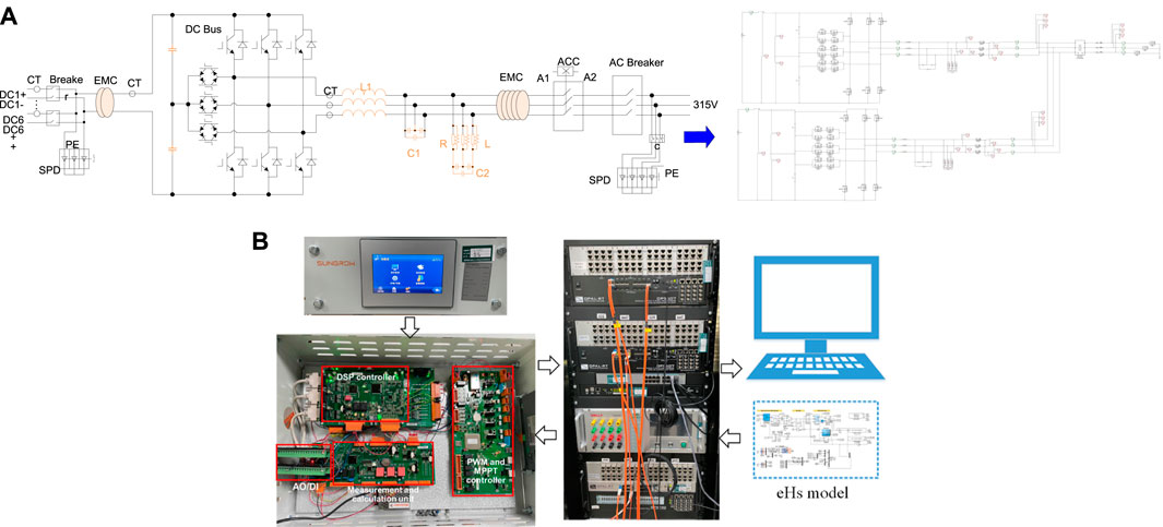
FIGURE 8. HIL test of the CV-PV controller: (A) eHS model of CV-PV; (B) HIL test platform.
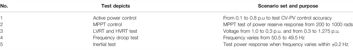
TABLE 2. Case 2 scenario description.
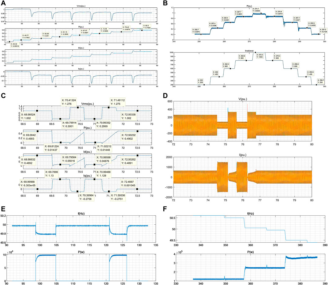
FIGURE 9. HIL test results of CV-PV: (A) active power control from 0.1 to 0.8 p.u., (B) MPPT control test from 200 to 1000 radiation, (C) and (D) LVRT and HVRT test under 0.5 p.u. of rated power from 0.2 to 1.3 p.u. of rated voltage, (E) frequency droop test, and (F) inertial test.
The active power of the CV-PV unit can be flexibly controlled, and the reaction time is less than 5 ms, indicating a quick control accuracy, as shown in Figures 9A,B. Based on the results in Figures 9C,D, the controller’s transient behaviors are compatible with the original CC-PV (d). Moreover, in Figures 10E,F, the simulation results clearly illustrate that the frequency and inertia characteristics have an influence on the controller’s output. The HIL test verifies the proposed controller’s validity and benefits.
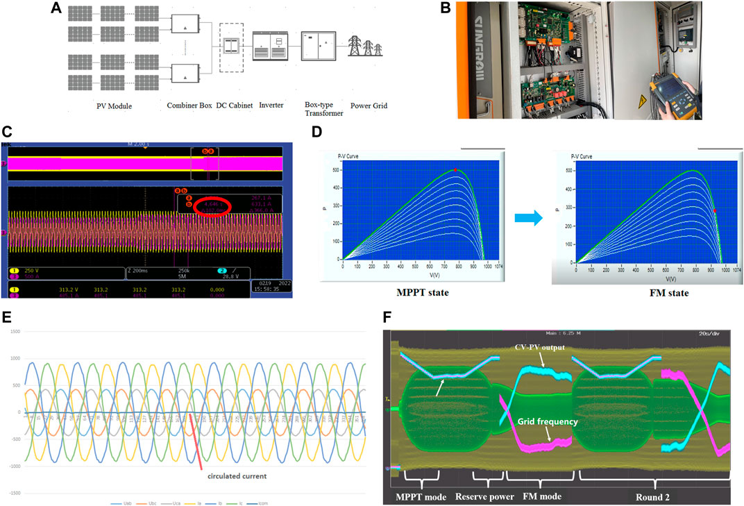
FIGURE 10. CV-PV controller performance test based on a demonstration project: (A) structure of the PV generation system, (B) project reconstruction point of the controller, (C) switching control results from CC-PV to CV-PV, (D) mode switch test from the MPPT mode to FM mode, (E) parallel test of two CV-PV units, and (F) frequency dynamic response test.
3.3 Case 3
A demonstration project is introduced here to verify the validity of the grid-forming strategy. The hybrid renewable station which consists of wind and solar energy is located in the middle of Hubei province, China. The capacity of permanent magnet direct-drive wind is 41.6 MW, while the rated photovoltaic is about 50 MW. Considering the economic and construction aspects, about 60% of PV units are upgraded as voltage-source by utilizing the same CV-PV controller in Case 2. The technical transformation enables the CV-PV to achieve the following functions, especially including the droop and inertia control mode, PQ control mode, seamless switching between them, and provision of reactive voltage support.
Several frequency disturbances are exerted on the secondary windings of the current transformer. The PV responses and its inner MPPT control results are shown in Figure 10. For instance, the switching time in Figure 10C is approximately 102 ms, and the circulation current between two CV-PV is nearly 0. In Figure 10F, the frequency response and its inner power reservation results are present. According to the process of dynamic response, the effectiveness and correctness of the proposed algorithm in a real engineering project are tested.
4 Conclusion
This work introduced a unique grid-forming CV-PV controller that can be used to establish a nearly 100% renewable electricity system without the need for energy storage on the DC side. Under dynamic system operation and atmospheric conditions, the proposed control algorithm provides acceptable actual and reactive power services, as well as PV DC voltage stability. Based on a semi-physical platform and a practical photovoltaic demonstration project, the major conclusions include the following:
1) To intelligently capture and release PV energy, the study built a DC voltage collapse-prevention controller that worked in combination with a simpler frequency and inertia controller. The experimental findings based on a semi-physical platform and a realistic DSP digital controller confirmed that the controller has high dynamic performance and stability.
2) With the suggested model built by the time accounting-storage approach, the CV interface and controller framework for PVs are proposed without integrating energy storage. The model anticipated the conflict between frequency regulation and curve control using the MPPT. The outcomes of the demonstration project attested to the method’s efficacy.
Admittedly, concerning the proposed planning model, a few aspects can be enriched, such as the reduction of reserved power and the consideration of the supportability of transient reactive power.
Data Availability Statement
The original contributions presented in the study are included in the article/Supplementary Material; further inquiries can be directed to the corresponding author.
Author Contributions
PH selected and studied the sources, designed the structure of the manuscript, and wrote the first draft of the manuscript. KJ and XJ contributed with supervision over the study of the literature and the writing of the manuscript. KC and DL modified the topology of this manuscript. DT designed the HIL test platform. All authors contributed to manuscript revision, read, and approved the submitted version.
Funding
This research received funding from the science and technology project of the State Grid Corporation of China, project number: 4000-202222070A-1-1-ZN.
Conflict of Interest
Authors PH, KJ, XJ, DT, DL, KC and WW were employed by State Grid Hubei Electric Power Company Limited.
Publisher’s Note
All claims expressed in this article are solely those of the authors and do not necessarily represent those of their affiliated organizations, or those of the publisher, the editors, and the reviewers. Any product that may be evaluated in this article, or claim that may be made by its manufacturer, is not guaranteed or endorsed by the publisher.
References
Awal, M. A., Yu, H., Lukic, S., and Husain, I. (2020). Droop and Oscillator Based Grid-Forming Converter Controls: A Comparative Performance Analysis. Front. Energy Res. 8, 3–6. doi:10.3389/fenrg.2020.00168
Blakers, A., Stocks, M., Lu, B., Cheng, C., and Stocks, R. (2019). Pathway to 100% Renewable Electricity. IEEE J. Photovoltaics 9 (6), 1828–1833. doi:10.1109/JPHOTOV.2019.2938882
Buraimoh, E., Davidson, I. E., and Martinez-Rodrigo, F. (2021). Decentralized Fast Delayed Signal Cancelation Secondary Control for Low Voltage Ride-Through Application in Grid Supporting Grid Feeding Microgrid. Front. Energy Res. 9, 4–8. doi:10.3389/fenrg.2021.643920
Debnath, S., Marthi, P. R. V., Xia, Q., Pan, J., Saeedifard, M., Vipin, V. N., et al. (2021). Renewable Integration in Hybrid AC/DC Systems Using a Multi-Port Autonomous Reconfigurable Solar Power Plant (MARS). IEEE Trans. Power Syst. 36 (1), 603–612. Jan. 2021. doi:10.1109/TPWRS.2020.3037520
Dong, D., Wen, B., Boroyevich, D., Mattavelli, P., and Xue, Y. (2015). Analysis of Phase-Locked Loop Low-Frequency Stability in Three-phase Grid-Connected Power Converters Considering Impedance Interactions. IEEE Trans. Ind. Electron. 62 (1), 310–321. doi:10.1109/tie.2014.2334665
Fang, J., Li, X., Li, H., and Tang, Y. (2018a). Stability Improvement for Three-phase Grid-Connected Converters through Impedance Reshaping in Quadrature-Axis. IEEE Trans. Power Electron. 33 (10), 8365–8375. doi:10.1109/tpel.2017.2777972
Fang, J., Tang, Y., Li, H., and Li, X. (2018b). A Battery/Ultracapacitor Hybrid Energy Storage System for Implementing the Power Management of Virtual Synchronous Generators. IEEE Trans. Power Electron. 33 (4), 2820–2824. doi:10.1109/TPEL.2017.2759256
Liu, F., Duan, S., Liu, F., Kang, B., and Kang, Y. (2008). A Variable Step Size INC MPPT Method for PV Systems. IEEE Trans. Ind. Electron. 55 (7), 2622–2628. doi:10.1109/TIE.2008.920550
Fu, X., Sun, J., Huang, M., Tian, Z., Yan, H., Iu, H. H.-C., et al. (2021). Large-Signal Stability of Grid-Forming and Grid-Following Controls in Voltage Source Converter: A Comparative Study. IEEE Trans. Power Electron. 36 (7), 7832–7840. doi:10.1109/TPEL.2020.3047480
He, X., Geng, H., Li, R., and Pal, B. C. (2020). Transient Stability Analysis and Enhancement of Renewable Energy Conversion System during LVRT. IEEE Trans. Sustain. Energy 11 (3), 1612–1623. doi:10.1109/tste.2019.2932613
Hua, T., Yan, X., and Fan, W. (2017). “Research on Power Point Tracking Algorithm Considered Spinning Reserve Capacity in Gird-Connected Photovoltaic System Based on VSG Control Strategy,” in IEEE 3rd International Future Energy Electronics Conference and ECCE Asia (IFEEC 2017 - ECCE Asia), 2059–2063. doi:10.1109/IFEEC.2017.7992368
Imai, H., Orihara, D., Iioka, D., and Saitoh, H. (2018). A Novel Virtual Synchronous Generator Control of PMSG-Based Wind Generation System to Enhance Transient Stability of Power System,” in IEEE Electronic Power Grid eGrid, 1–6. doi:10.1109/eGRID.2018.8598690
Li, M., Zhang, X., and Zhao, W. (2018). A Novel Stability Improvement Strategy for a Multi-Inverter System in a Weak Grid Utilizing Dual-Mode Control. Energies 11 (8), 2144. doi:10.3390/en11082144
Liu, J., Golpira, H., Bevrani, H., and Ise, T. (2021). Grid Integration Evaluation of Virtual Synchronous Generators Using a Disturbance-Oriented Unified Modeling Approach. IEEE Trans. Power Syst. 36 (5), 4660–4671. doi:10.1109/tpwrs.2021.3061615
Sang, S., Zhang, C., Zhang, J., Shi, G, and Deng, F (2022). Analysis and Stabilization Control of a Voltage Source Controlled Wind Farm under Weak Grid Conditions. Front. Energy 2095–1698, 3–8. doi:10.1007/s11708-021-0793-5
Silwal, S., Taghizadeh, S., Karimi-Ghartemani, M., Hossain, M. J., and Davari, M. (2019). An Enhanced Control System for Single-phase Inverters Interfaced with Weak and Distorted Grids. IEEE Trans. Power Electron. 34 (12), 12538–12551. doi:10.1109/tpel.2019.2909532
Sun, Z., Zhu, F., and Cao, X. (2021). Study on a Frequency Fluctuation Attenuation Method for the Parallel Multi-VSG System. Front. Energy Res. 9 , 4–6. doi:10.3389/fenrg.2021.693878
Wang, X., Taul, M. G., Wu, H., Liao, Y., Blaabjerg, F., and Harnefors, L. (2020). Grid-Synchronization Stability of Converter-Based Resources-An Overview. IEEE Open J. Ind. Appl. 1, 115–134. doi:10.1109/ojia.2020.3020392
Wu, C., Zhang, X. -P., and Sterling, M. J. H. (2021). Global Electricity Interconnection with 100% Renewable Energy Generation. IEEE Access 9, 113169–113186. doi:10.1109/ACCESS.2021.3104167
Wu, W., Zhou, L., Chen, Y., Luo, A., Dong, Y., Zhou, X., et al. (2019). Sequence-Impedance-Based Stability Comparison between VSGs and Traditional Grid-Connected Inverters. IEEE Trans. Power Electron. 34 (1), 46–52. doi:10.1109/tpel.2018.2841371
Yuan, X. B., Wang, F., Boroyevich, D., Yongdong, L., and Burgos, R. (2009). DC-link Voltage Control of a Full Power Converter for Wind Generator Operating in Weak-Grid Systems. IEEE Trans. Power Electron. 24 (9), 2178–2192. doi:10.1109/tpel.2009.2022082
Xu, J., Qian, Q., Zhang, B., and Xie, S. (2019). Harmonics and Stability Analysis of Single-phase Grid-Connected Inverters in Distributed Power Generation Systems Considering Phase-Locked Loop Impact. IEEE Trans. Sustain. Energy 10 (3), 1470–1480. doi:10.1109/tste.2019.2893679
Xu, J., Xie, S., Qian, Q., and Zhang, B. (2017). Adaptive Feedforward Algorithm without Grid Impedance Estimation for Inverters to Suppress Grid Current Instabilities and Harmonics Due to Grid Impedance and Grid Voltage Distortion. IEEE Trans. Ind. Electron. 64 (9), 7574–7586. doi:10.1109/tie.2017.2711523
Zhang, X., Xia, D., Fu, Z., Wang, G., and Xu, D. (2018). An Improved Feedforward Control Method Considering PLL Dynamics to Improve Weak Grid Stability of Grid-Connected Inverters. IEEE Trans. Ind. Appl. 54 (5), 5143–5151. doi:10.1109/tia.2018.2811718
Zhong, Q.-C., and Weiss, G. (2011). Synchronverters: Inverters that Mimic Synchronous Generators. IEEE Trans. Ind. Electron. 58 (4), 1259–1267. doi:10.1109/tie.2010.2048839
Keywords: grid-forming, voltage-source, controlled PV, 100% renewable electricity, DC voltage collapse-prevention controller
Citation: Hu P, Jiang K, Ji X, Tan D, Liu D, Cao K and Wang W (2022) A Novel Grid-Forming Strategy for Voltage-Source Controlled PV Under Nearly 100% Renewable Electricity. Front. Energy Res. 10:915763. doi: 10.3389/fenrg.2022.915763
Received: 08 April 2022; Accepted: 10 May 2022;
Published: 29 June 2022.
Edited by:
Tianqiao Zhao, Brookhaven National Laboratory (DOE), United StatesReviewed by:
Ming Wang, Shandong Jianzhu University, ChinaLinfei Yin, Guangxi University, China
Juan Wei, Hunan University, China
Copyright © 2022 Hu, Jiang, Ji, Tan, Liu, Cao and Wang. This is an open-access article distributed under the terms of the Creative Commons Attribution License (CC BY). The use, distribution or reproduction in other forums is permitted, provided the original author(s) and the copyright owner(s) are credited and that the original publication in this journal is cited, in accordance with accepted academic practice. No use, distribution or reproduction is permitted which does not comply with these terms.
*Correspondence: Pan Hu, aHVwYW5pbndoQHdodS5lZHUuY24=