- School of Physical and Mathematical Sciences, Nanjing Tech University, Nanjing, China
In this study, a novel fluidic oscillator suitable for use as a key component of a flow control device is proposed and investigated through numerical simulations. The new layout adds resonators to a typical fluidic oscillator with dual feedback channels, and the length of the feedback loop is designed to be adjustable. This fluidic oscillator with movable feedback channels and resonators can generate a jet with an adjustable frequency, and it has smaller total pressure loss than the baseline model. Numerical results show that the movement of the feedback channels regulates the degree of coupling between the feedback channels and resonators to generate different orders of jet frequencies. This self-excited fluidic oscillator with adjustable jet frequency is more adaptive than typical designs when dealing with complex flow separation conditions, and it will be more stable because the frequency adjustment requires neither high-frequency movable mechanisms nor external energy input. Moreover, the frequency switching phenomenon is observed in special cases, which may help improve the efficiency of the compressor blades with a drastically changed dominant frequency under off-design conditions or with multiple dominant frequencies, such as tip leakage flow and shock–boundary layer interaction.
1 Introduction
The efficiency and stability of compressors at high loads directly affect the performance of aeroengines. When blade loads are increased to levels far above the current aerodynamic design level, flow separation usually occurs due to high inverse pressure gradients or shock–boundary layer interaction, causing a dramatic decrease in fluid mechanical efficiency and even engine surge. Through flow control techniques, flow separation can be reduced or even eliminated, thereby improving the pressure ratio, efficiency, and stability margin of compressors considerably (Liu et al., 2019; Qin et al., 2020; Lu et al., 2022).
Flow control mainly includes steady and unsteady flow control. In recent decades, researchers have shown great interest in unsteady flow control techniques that utilize flow instabilities. The main difference between steady and unsteady flow control techniques lies in whether or not the flow control excitation is time-dependent. The advantage of unsteady flow control over steady flow control is that it can achieve the same control effect with an energy saving of one to two orders of magnitude (Greenblatt and Wygnanski, 2000). Therefore, unsteady flow control has elicited attention from researchers and has become a focus of flow control research.
Unsteady flow control mainly includes acoustic excitation (Lepicovsky et al., 1986; Nishioka et al., 1987; Açıkel and Genç, 2016), synthetic jets (Glezer and Amitay, 2002) (Cao et al., 2020), unsteady blowing and suction (Kim et al., 2017), wall oscillation (Choi et al., 2002), and traveling wave wall control (Wu et al., 2003) (Lu et al., 2019). Belonging to unsteady blowing, fluidic oscillators are devices that can create a sweeping jet with a fixed frequency through a stable mass flow input. Oscillation in fluidic oscillators is produced by the Coanda effect, which attaches the fluid stream alternatively to one of the adjacent walls in the mixing chamber. The produced oscillation is self-induced and self-sustained (Tomac and Sundström, 2019). If the inlet and outlet of a fluidic oscillator are connected to a high-pressure and a low-pressure air source, respectively, the fluidic oscillator can utilize the flow instability to enable the outlet to generate a periodic sweeping jet, which can be used as the unsteady excitation required for unsteady flow control. As an unsteady flow control method, self-excited fluidic oscillators have a simple, reliable, low-maintenance geometry and can generate a self-sustaining and oscillating periodic jet without the use of movable parts. Thus, they have good application prospects. Their potential has been explored in many areas, such as fluid mechanics and aeronautics. Therefore, the demand for fluidic oscillators in engineering applications has increased considerably.
Fluidic oscillators have the potential to function as flow control devices by producing oscillating velocity fields. However, their utilization as unsteady flow control devices has received wide attention from researchers since 2010s. Many typical fluidic oscillators are very efficient in generating oscillating velocity fields and their effects and mechanism have been thoroughly studied in recent years due to their robustness and potential to meet most of the application requirements. Cerretelli and Kirtley (Cerretelli and Kirtley, 2009) experimentally investigated the control effect of a fluidic oscillator on flow separation in a diffuser and found that the fluidic oscillator can save 60% jet momentum compared with steady flow control when the flow field is fully reattached. Koklu (Koklu, 2018) compared the jet generated by a fluidic oscillator with those generated by several common flow control methods, such as steady jet, vortex-generating jet, and vortex generator through experiments and reported that the control performance of the fluidic oscillator is better than that of the steady jet and vortex-generating jet in the separation flow of the ramp structure. Wang et al. (Wang et al., 2019) proposed the concepts of high-pressure compressed wave and low-pressure expansion wave and used pressure wave reflection theory to explain oscillation behavior. Ostermann et al. (Ostermann et al., 2017) (Ostermann et al., 2019) addressed the flow control mechanism of fluidic oscillators and found that because the sweeping jet is on a plane perpendicular to the external crossflow, the effect of the jet is similar to that of the streamwise vortical structures generated by a vortex generator. Tomac and de Luzan (Tomac and de Luzan, 2020) experimentally and numerically investigated and characterized a synchronized fluidic oscillator, which is especially helpful for solving flow control problems exhibiting two separation points, such as flow-over cylinders or surfaces exposed to differential pressure (i.e., wingtips). Some researchers have also focused on self-excited fluidic oscillators for engineering applications and have conducted full-scale experiments and numerical simulations. Cerretelli et al. (Cerretelli et al., 2010) used a built-in fluidic oscillator to control a DU96 airfoil representing a typical wind turbine blade and discovered that appropriate control parameters can increase the airfoil lift by up to 60%. Shmilovich et al. (Shmilovich et al., 2018) placed an array of multiple fluidic oscillators on the vertical tail of an aircraft and verified the effectiveness of this flow control approach through numerical simulations and experiments at the whole-aircraft level of the B757 demonstrator.
Unsteady flow control devices require a broad range of excitation frequencies for effective operation in some cases. For example, in a compressor at an off-design point, the dominant frequency of the separated flow differs from that at the design point. This condition means that the optimum flow control frequency also changes, so the frequency of unsteady flow control devices, such as fluidic oscillators, needs to be adjusted under different operating conditions. Flows with tip leakage, corner separation, or shock–boundary layer interactions also have two different dominant frequencies. Under different operating conditions, modes with different dominant frequencies need to be controlled. Thus, researchers have attempted to establish methods to change the frequency of flow control devices. As unsteady fluid control devices, fluidic oscillators typically adjust the sweeping frequency of the output jet through its mass flow rate. However, other existing methods can be used to adjust the jet frequency. For example, Tomac and Sundström (Tomac and Sundström, 2019) added two control jets in the fluidic oscillator mixing chamber. This approach can change the jet frequency of the oscillator through the K-H instability between the two control jets and the mainstream to generate ultra-high frequency jets. Culley (Culley, 2006) added a solenoid pressure valve to the inlet of the oscillator to regulate the pressure in the control channel and thus control the frequency of the jets generated by the devices. The highest frequency measured from this experimental device is 312 Hz due to the limitations in the switching speed of the solenoid valve. This frequency may still be relevant for some applications, but this device cannot handle flow control situations that require frequencies higher than 312 Hz. In addition, the constant external excitation and high-frequency motion of the components increase the energy consumption and reduce mechanical reliability. Moreover, Gregory et al. (Gregory et al., 2009) used a piezoelectric bender to control the frequency of a fluidic oscillator. Their design is similar to these with solenoid valves. Given that a bending tube is added, the frequency is affected by the characteristics of the moving parts when this method is adopted. In the frequency range of 0–250 Hz, oscillation frequency is independent of supply pressure. However, the efficiency of this approach decreases at frequencies exceeding the piezoelectric bender’s resonance frequency (121 Hz). Analysis of the existing techniques for changing the frequency of fluidic oscillators indicates that changing the frequency by adding movable parts, electric devices, or additional accessories may raise new issues, such as reduced engineering reliability, increased maintenance costs, shortened service life, and reduced energy utilization efficiency.
Aside from fluidic oscillators that can adjust jet frequency, we consider a new configuration that avoids using external excitation, high-frequency movable parts, or electromagnetic actuators. At present, there are two typical types of wall-attachment fluidic oscillator designs: with feedback channels and with resonators (Gregory and Tomac, 2013). For the fluidic oscillator with feedback channels, the frequency of the jet generated by the device is proportional to the flow rate through the oscillator (Ostermann et al., 2019). Thus, jet frequency can be adjusted via the flow rate. However, generating ultra-high-frequency jets is difficult. For the fluidic oscillator consisting of a conjugate acoustic resonator (Tesař et al., 2013), jet frequency is constant and independent of the flow rate through the fluidic oscillator. Ultra-high-frequency jets can be generated, but the jet frequency is difficult to adjust because it is determined by the geometry of resonators. Thus, we consider a new fluidic oscillator with movable feedback channels and resonators and attempt to combine the advantages of both, namely, the ability to adjust the frequency by flow rates while generating high frequencies and the ability to modulate the Strouhal number of the oscillator by moving the feedback channels, thus changing the oscillator characteristics.
In this study, the characteristics of the fluidic oscillator with feedback channels and resonators are studied numerically. In Section 2, the concept of the fluidic oscillator is introduced in terms of structural design ideas and principles. In Section 3, the numerical method used in this study is presented together with the structural parameters, mesh generation, and solver settings. Simulation reliability is also verified through a comparison with existing experimental results. In Section 4, we present the theoretical basis for the sweeping frequency in fluidic oscillators with only feedback channels and those with only resonators. In Section 5, we analyze the numerical results to express our understanding of the unique characteristics of the new fluidic oscillator. With this study, we hope to improve the understanding and application of fluidic oscillators with adjustable frequencies.
2 Concept of a fluidic oscillator with movable feedback channels and resonators
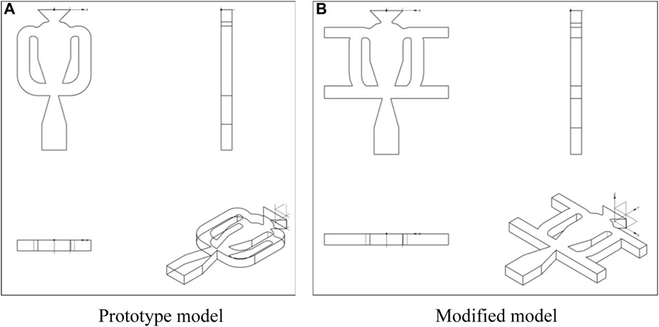
We propose a new fluidic oscillator with adjustable jet frequencies and sweeping amplitudes. For easy distinction, we refer to the baseline model used for reference as the “prototype model” and to the new proposed oscillator as the “modified model”. In terms of geometry, on the basis of the prototype fluidic oscillator shown in Figure 1A (adopted from Ref. (Cerretelli et al., 2010)), we add resonators at the beginning and end of each of the two feedback channels so that the fluidic oscillator has both feedback channels and resonators. We expect this design to combine the advantages of the two typical types of oscillators mentioned in the Introduction. The feedback channel is designed to move laterally within the stroke, thus allowing the adjustment of the oscillation characteristics to produce sweeping jets with different characteristics.
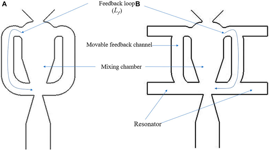
FIGURE 1. Comparison between (A) the prototype fluidic oscillator (Cerretelli et al., 2010) and (B) the fluidic oscillator with both feedback channels and resonators.
The specific structure of the fluidic oscillator with feedback channels and resonators is shown in Figure 1B. It includes an inlet, a mixing chamber, and an outlet, which are sequentially located on the central axis of the device and constitute the main flow path. A feedback loop consisting of a feedback channel and a resonator is provided both on the left and right, respectively, of the central axis of the device. If the resonator is not considered, the main flow path in the mixing chamber will adhere to the left or right wall surface of the mixing chamber due to the Coanda effect. For example, if the main flow path is attached to the right wall of the mixing chamber, the jet will be attached to the left wall of the outlet and form a right feedback loop, and the flow along the right feedback loop will push the main flow path at the entrance of the mixing chamber to attach it to the left wall of the mixing chamber. Next, the jet will flow along the right wall of the outlet and form a left feedback loop. These two processes occur alternately, thus forming a certain frequency of the sweeping jet at the outlet. Moreover, if the feedback channel is not considered, a standing wave with a fixed frequency will be generated at the entrance of the mixing chamber due to the presence of resonators on both sides of the entrance of the mixing chamber, making the jet frequency consistent with this standing wave frequency (Field and Fricke, 1998).
Given that resonators and feedback channels exist simultaneously, the characteristics of the oscillator in this study are formed by the joint action and mutual coupling of resonators and feedback channels. By changing the feedback loop length through the movement of the feedback channel, the jet characteristics are likely to be changed. And the jet sweeping angle and frequency can be adjusted through the different degrees of coupling between the feedback channels and resonators. This approach can effectively control the flow for different separation vortex frequencies and improve the adaptability of the device to the working conditions.
3 Numerical methods
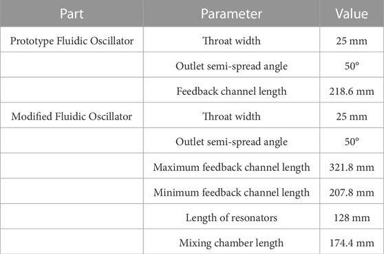
In this study, the sweeping jet is generated by a fluidic oscillator with both feedback channels and resonators (Figure 2). This oscillator is a modification of a prototype oscillator, which has been examined and characterized in various studies (e.g., Ostermann et al., 2018). The spatial oscillations of the jet are induced only by internal dynamics and geometry, so the generated jet is self-induced and self-sustained. With reference to the modified fluidic oscillator, the width d of the outlet (i.e., throat) is 25 mm, the length of the resonator (denoted as
A computational fluid dynamics (CFD) approach is used to evaluate the characteristics of the fluidic oscillator in different modes, including the effect of the length of the feedback channels on the sweeping frequency of the fluidic oscillator and the total pressure loss of the oscillator. The simulations are implemented on a workstation that uses an octa-core Intel Core i7 9700 CPU. An unsteady flow case needs about 20 h to finish computation. The validity and feasibility of the numerical method are verified based on the prototype. The modified model includes the design of the feedback channel as a movable mechanism so that the total length of the feedback loop can be adjusted within a certain range, which may also result in a variation in the Strouhal number.
To simulate the sweeping jet generated by the fluidic oscillator with moveable feedback channels and resonators, a structured mesh is constructed using ANSYS ICEM. The mesh topology is shown in Figure 3, and 16 3D blocks are used. A grid-independence test is performed based on the prototype, and Figure 4 shows that the jet frequency and total pressure loss coefficient generated by the prototype are nearly invariant for grid numbers larger than 860,000. Therefore, using the grid number of about 1,000,000 can save computational resources while obtaining a sufficiently high computational accuracy. The grid of the feedback channel part is divided independently, and the moving mesh is used to generate meshes at different positions. Before the mesh is moved to the designed position, the translational speed is maintained at a low level to avoid unsteady effects.
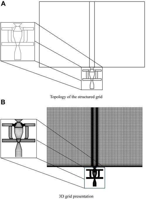
FIGURE 3. (A) Grid topology and (B) 3D Grid of the fluidic oscillator with both feedback channels and resonators.
The ideal air model is selected as the fluid model. The k-omega shear stress transport (k-ω SST) turbulence model is used in ANSYS Fluent to calculate the steady flow as the initial field, and unsteady numerical simulations are performed using large eddy simulation (LES). In LES, the wall-adapting local eddy–viscosity (WALE) sub-grid model is selected. Given that the mesh of the feedback channels and the main body of the oscillator structure are divided separately, interfaces are set between the moving mesh (feedback channel mesh) and the stationary mesh (the rest of the mesh) so that each part of the mesh is connected. The boundary condition at the inlet of the fluidic oscillator is constrained by a given mass flow rate, and a constant static pressure of standard atmosphere is provided at the outlets. Moreover, a periodic boundary is set in the staggered direction, thus reducing the cost of the 3D LES calculation. In this calculation, dual time stepping is employed, and the physical time step is set to 1 × 10⁻³ s. The flow losses of the device are evaluated by the total pressure loss coefficient, which is defined as follows:
where
The numerical simulation (CFD) results of the prototype fluidic oscillators are compared with the experimental results (Ostermann et al., 2018), as illustrated in Figures 5A, B. Figure 5A shows the transient sweeping jet angle of the prototype fluidic oscillator obtained by the simulation (operating at a jet velocity of 19 m/s) and experiment (the experimental data obtained from Ref. (Ostermann et al., 2018)). Figure 5B presents the jet frequency as a function of velocity obtained from the numerical simulations and experiments. In CFD, the jet angle is obtained by monitoring the normal and tangential flow velocity components at the throat of the outlet, whereas in the experiments, the sweeping angle is monitored on a section at a certain distance from the outlet. Thus, the two results show some differences. According to Figures 5A, B, the CFD results generally agree with the experimental results. The sweeping angle of the jet obtained by CFD demonstrates a cyclic trend that approximates a sinusoidal function, which is consistent with the experimentally obtained results. In addition, the experimental dominant frequency of the jet is 9.31 Hz, which is very close to the value of 9.66 Hz obtained by CFD. Figures 5A, B illustrate that the numerical method can predict the transient characteristics of the unsteady flow field of the oscillator. Therefore, this numerical method can be applied to the numerical computation of the modified fluidic oscillator in the subsequent sections.
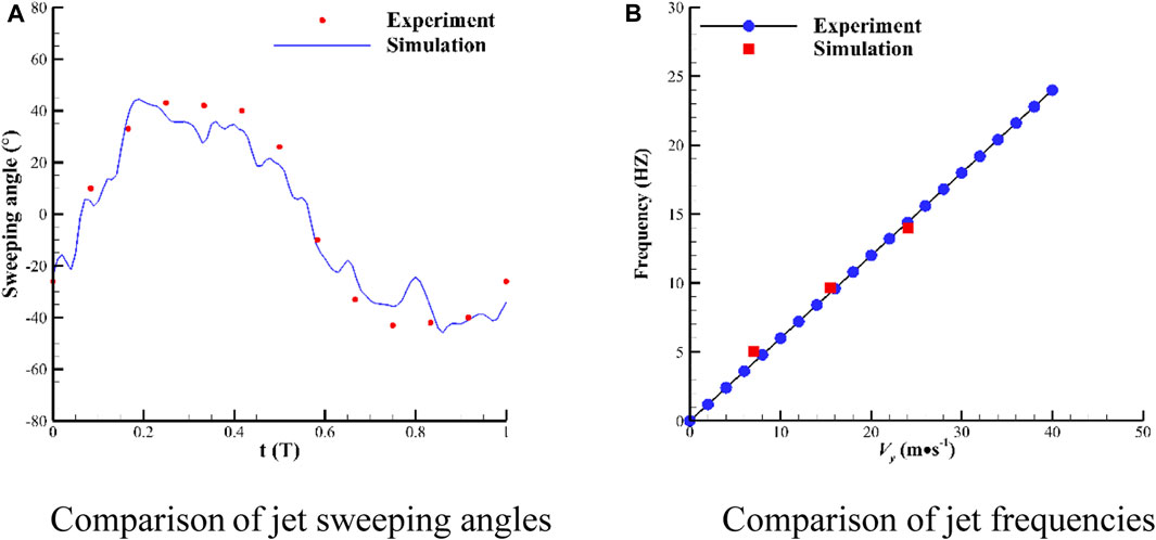
FIGURE 5. Comparison of (A) jet sweeping angles (T denotes a time period) and (B) jet frequencies between numerical and experimental results.
4 Theory of sweeping frequency in two types of fluidic oscillators
In the prototype, jet frequency is proportional to velocity at low jet velocities, but the jet frequency of the fluidic oscillator with resonators is related only to the structural parameters (e.g., length of the resonator). The modified fluidic oscillator combines the structural features of the two oscillators. So, the following sections analyzes the frequency characteristics of the prototype and modified fluidic oscillator theoretically.
4.1 Fluidic oscillators with feedback channels only
In this section, we analyze the theoretical formulation of jet frequency in the prototype oscillator and apply numerical data to it.
For fluidic oscillators with feedback channels only, jet sweeping frequency is related to the geometry and mass flow rate of the oscillator. Ostermann et al. (Ostermann et al., 2019) and Simões et al. (Simões et al., 2005) proposed the equation for the sweeping jet frequency of a fluidic oscillator with feedback channels as follows:
where
Thus,
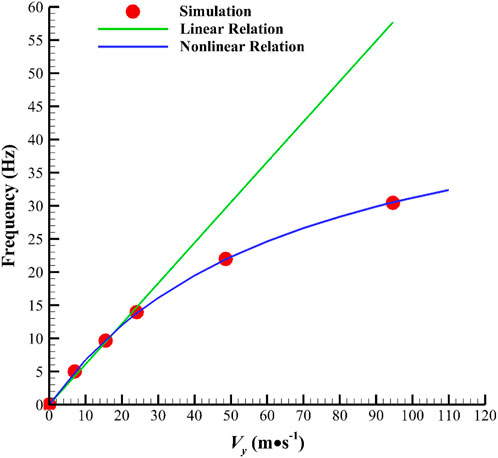
We use the relations in Eqs 2, 3 to fit the numerical simulation results of the prototype, as shown in Figure 6. In Figure 6, when the jet velocity is below 30 m/s, the Mach number is much lower than 0.3, and the compressibility effect is negligible. Under this circumstance, the frequency of the jet generated by the oscillator is approximately proportional to the jet velocity, and the Strouhal number obtained from the numerical simulation is calculated from this slope as 0.0157, which basically coincides with the experimental value of 0.015 in Ref. (Ostermann et al., 2018). When the jet velocity is higher than 30 m/s, the increment in jet frequency decreases with the increase in the Mach number, indicating a nonlinear relationship.
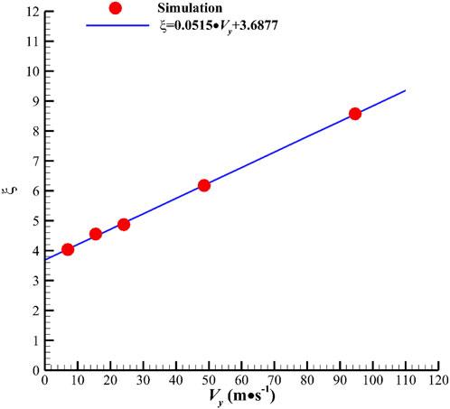
In Eq. 2,
By substituting
4.2 Fluidic oscillator with dual quarter-wave resonators
In this section, we derive the jet frequency law of the fluidic oscillator with dual quarter-wave resonators. The relationship between jet frequency and resonator length in a fluidic oscillator with a single quarter-wave resonator has been proposed in Ref. (Field and Fricke, 1998). The relationship between jet frequency and resonator length needs to be derived for oscillators with dual resonators because modified fluidic oscillators have two symmetrical resonators. The derived equations for an oscillator with two symmetrical resonators are similar to those with a single quarter-wave resonator.
In a bounded medium, such as resonator structures in an oscillator, a quarter-wave resonator has two boundaries where reflection can occur: the open end and the closed end. Unlike a progressive wave in an unbounded medium, a wave set in a linear system, such as a fluidic oscillator with a resonator, is reflected off the two boundaries. Therefore, it propagates continuously between the two boundaries. Each time a vibratory source acts on the open end of the resonator, the vibratory source transfers energy to the air in the resonator cavity. This process forms standing waves in the cavity, creating a resonant state.
Next, the frequency equation of the modified fluidic oscillator (with two resonators) is derived. The wave generated in one direction is
where
The wave generated in the other direction is
where
We know that
In accordance with the first boundary condition, the following expression is obtained:
Therefore,
From the second boundary condition, the following expression is obtained:
Thus,
Hence, we can deduce that
The minimum value of
When the modified model has resonators only, the two near-inlet resonators play the main role in determining the jet frequency. The frequency of the jet may be fractional or integral multiples of the characteristic frequency of the resonators (i.e., subharmonic or harmonic frequency) because of the nonlinear effect in the flow field and the coupling between the resonator and feedback channel.
For the prototype fluidic oscillator (Ostermann et al., 2019), when the shape of the fluidic oscillator is fixed, the value of the Strouhal number is nearly invariant. Strouhal number
However, the present study changes the structure of the feedback loops through the movement of the movable feedback channels, thus causing
Given that the jet frequency generated by the fluidic oscillator with resonators is fixed, according to Eq. 16,
5 Numerical results and analysis—characteristics of the fluidic oscillator with both feedback channels and resonators
In this study, the feedback channel is designed as a movable component on the basis of the prototype model. To reflect the relative length of the feedback channel, the ratio of feedback channel length to resonator length is defined as
Thus, three typical states represented by
5.1 Flow loss characteristics
The fluidic oscillator, as a flow control method, is designed to suppress external flow separation losses, and it requires a low level of flow losses within itself. In the numerical simulation, the total pressure loss coefficient (Eq. 1) is used to evaluate the flow loss characteristics of the device, and Figure 8 shows the comparison of total loss coefficients between the prototype and the modified model (
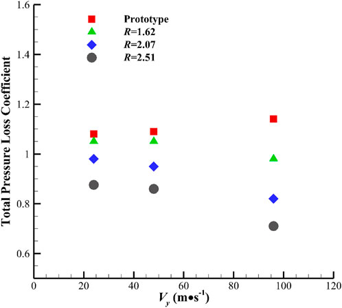
FIGURE 8. Comparison of the total pressure loss coefficients of the prototype and modified model under different
Numerical calculations of the prototype and the modified fluidic oscillator with different
The modified oscillator in the
Furthermore, with the increase in
5.2 Frequency characteristics
The sweeping frequencies for different
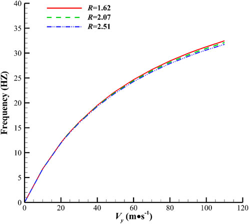
FIGURE 9. Theoretically calculated jet sweeping frequency versus
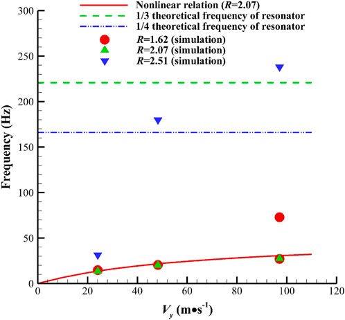
In Figure 10, the theoretical jet frequency of the fluidic oscillator is calculated with Eq. 2, and the theoretical characteristic frequency of the fluidic oscillator with symmetrical resonators is calculated with Eq. 4. The one-third and one-quarter theoretical frequencies of the resonator are also plotted. Analysis is conducted by comparing the theoretical relations and simulated results. Observation of the corresponding frequencies at three velocities in the condition
Notably, we obtain a new finding, as shown in Figure 10. The red dot (R = 1.62) in Figure 10 at the jet velocity of 96 m/s indicates frequency bifurcation, which means the sweeping frequency alternately switches between 27 Hz and 73 Hz, where 27 Hz is in accordance with the theoretical relation and 73 Hz is unexpected. The sweeping angle also presents the switching phenomenon, which will be discussed further in Section 5.3. This phenomenon is the state of switching from a low frequency and a high amplitude to a high frequency and a low amplitude over time (Figure 12C, which illustrates the time-domain curve ofthe sweeping angle). Given that this phenomenon is only observed in cases with high jet velocity, the phenomenon occurs beyond a certain Reynolds number threshold. As shown in Figure 10, the low frequency is determined by the feedback channel, and the high frequency is related to the resonator. The authors suggest that the phenomenon is relevant to the competition of the feedback channel and the resonator for dominating the main stream alternately, but a certain randomness exists in the domination at a certain moment (Figure 12C), which will be described in detail in Section 5.4.
Figure 10 also depicts the simulated corresponding frequencies at three different velocities in the
The role of this oscillator is to adjust the frequency. The movement of the feedback channel changes the length of the feedback loop (denoted by different
5.3 Sweeping magnitude characteristics
This section analyzes the sweeping angle magnitude of the jet. A data processing method is needed to obtain the effective sweeping angle amplitude because the jet angle curve is only approximately sinusoidal. We treat the jet angle as an oscillation described as
where
where
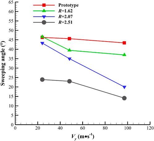
By imitating the calculation of voltage magnitude and using Eqs. (17) and (18), we can obtain the magnitude of the sweeping angle produced by the fluidic oscillator. Figure 11 shows a comparison of the amplitude values of the prototype and the modified model with different
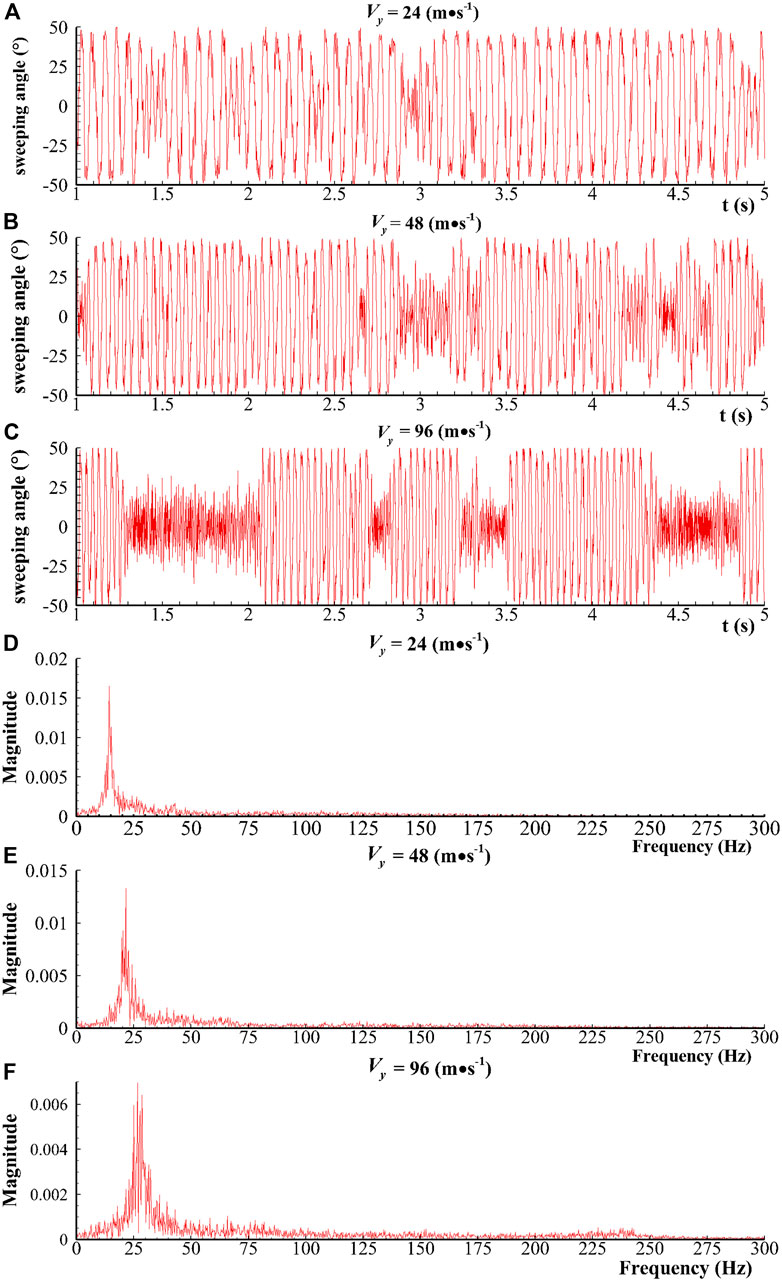
FIGURE 12. (A–C) Sweeping angle in time domain and (D–F) frequency magnitude in frequency domain (R = 1.62).
5.4 Unsteady characteristics
This section analyzes some special unsteady characteristics due to different parameters of jet velocity
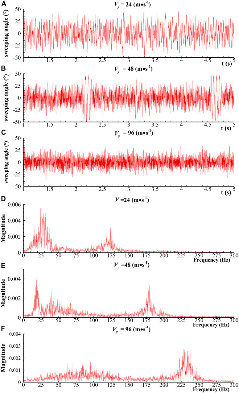
FIGURE 13. (A–C) Sweeping angle in time domain and (D–F) frequency magnitude in frequency domain (R = 2.51).
To clearly illustrate the frequency switching phenomenon, two typical unsteady flow fields at
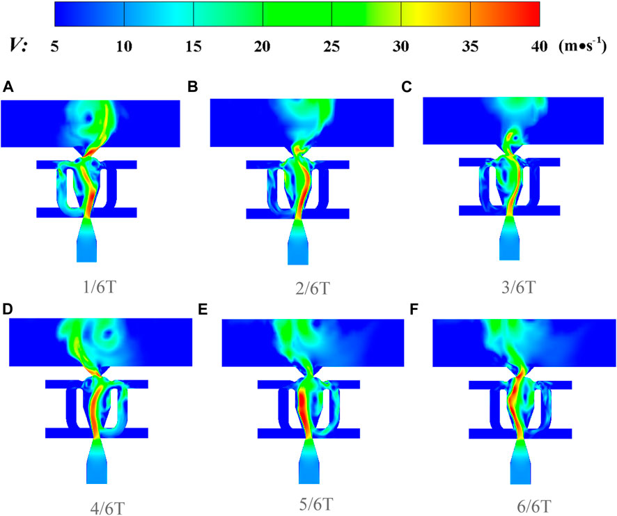
FIGURE 14. Transient velocity contour of the flow field at (A) 1/6T, (B) 2/6T, (C) 3/6T, (D) 4/6T. (E) 5/6T, and (F) 6/6T modes (T is a sweeping period and R = 1.62 and Vy = 24 m/s).
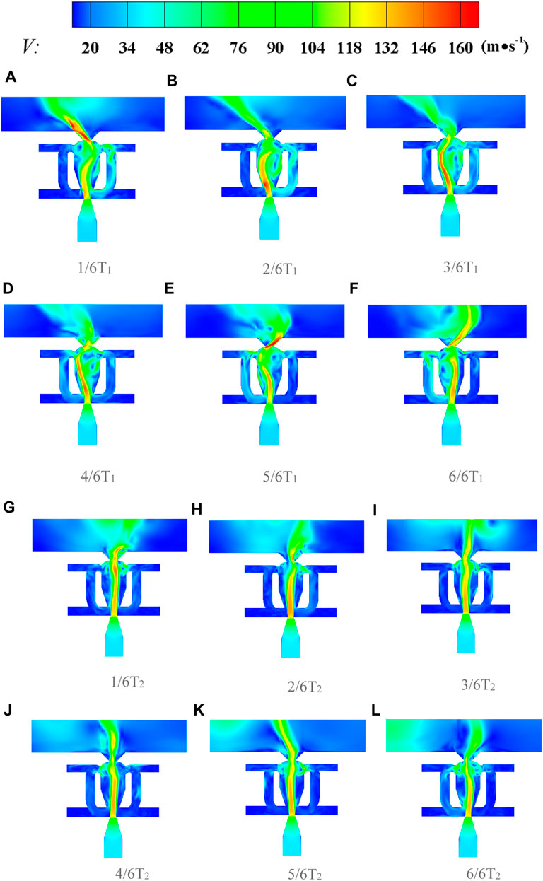
FIGURE 15. Transient velocity contour of the flow field at (A) 1/6T1, (B) 2/6T1, (C) 3/6T1, (D) 4/6T1, (E) 5/6T1, (F) 6/6T1, (G) 1/6T2, (H) 2/6T2, (I) 3/6T2, (J) 4/6T2, (K) 5/6T2, and (L) 6/6T2 modes (T1 is one oscillation period at a lower frequency, and T2 is one oscillation period at a higher frequency. The figure presents a process of frequency switching from period T1 to T2. The time required for this process varies and the figure shows a typical transition. (R = 1.62 and Vy = 96 m/s in this figure).
6 Conclusion
In this study, we propose a fluidic oscillator with feedback channels and resonators and investigate its characteristics in terms of internal flow losses, jet frequencies, sweeping angles, and unsteady flow field characteristics through numerical simulation. The main conclusions are as follows.
1. The total pressure loss of the prototype fluidic oscillator will increase by 5.6% when the normal velocity of the sweeping jet
2. The analysis of jet frequency indicates that theoretically, a change in the feedback channel length (denoted by a nondimensional parameter
3. Frequency switching, a phenomenon where the jet randomly switches from 27Hz frequency and 49
Data availability statement
The raw data supporting the conclusion of this article will be made available by the authors, without undue reservation.
Author contributions
ZY: date Curation, Writing—Original Draft. YL: date Curation, Writing—Original Draft. XY: Writing—Original Draft. QD: Date Curation. WL: conceptualization, Methodology, Writing—Review and Editing. All authors contributed to the article and approved the submitted version.
Funding
This research was funded by the National Natural Science Foundation of China (grant number 52106046), the Natural Science Foundation of Jiangsu Province (grant number BK20200680) and the National Students’ platform for innovation and entrepreneurship training program (grant number 202310291089Z).
Acknowledgments
The authors wish to express their gratitude to Department of Engineering Mechanics (affiliated with School of Physical and Mathematical Sciences, Nanjing Tech University) for technical support.
Conflict of interest
The authors declare that the research was conducted in the absence of any commercial or financial relationships that could be construed as a potential conflict of interest.
Publisher’s note
All claims expressed in this article are solely those of the authors and do not necessarily represent those of their affiliated organizations, or those of the publisher, the editors and the reviewers. Any product that may be evaluated in this article, or claim that may be made by its manufacturer, is not guaranteed or endorsed by the publisher.
References
Açıkel, H. H., and Genç, M. S. (2016). Flow control with perpendicular acoustic forcing on NACA 2415 aerofoil at low Reynolds numbers. Proc. IMechE, Part G - J. Aerosp. Eng.230, 2447–2462. doi:10.1177/0954410015625672
Cao, S., Dang, N., Ren, Z., Zhang, J., and Deguchi, Y. (2020). Lagrangian analysis on routes to lift enhancement of airfoil by synthetic jet and their relationships with jet parameters. Aerosp. Sci. Technol.104, 105947. doi:10.1016/j.ast.2020.105947
Cerretelli, C., and Kirtley, K. (2009). Boundary layer separation control with fluidic oscillators. J. Turbomach.131 (4), 29–38. doi:10.1115/1.3066242
Cerretelli, C., Wuerz, W., and Gharaibah, E. (2010). Unsteady separation control on wind turbine blades using fluidic oscillators. AIAA J.48 (7), 1302–1311. doi:10.2514/1.42836
Choi, J., Xu, C. X., and Sung, H. J. (2002). Drag reduction by spanwise wall oscillation in wall-bounded turbulent flows. AIAA J.40, 842–850. doi:10.2514/3.15133
Culley, D. (2006). “Variable frequency diverter actuation for flow control,” in 3rd AIAA Flow Control Conference, AIAA Paper, San Francisco, California, 05 June 2006 - 08 June 2006. 2006-3034.
Field, C. D., and Fricke, F. R. (1998). Theory and applications of quarter-wave resonators: A prelude to their use for attenuating noise entering buildings through ventilation openings. Appl. Acoust.53 (3), 117–132. doi:10.1016/s0003-682x(97)00035-2
Glezer, A., and Amitay, M. (2002). Synthetic jets. Annu. Rev. Fluid Mech.34, 503–529. doi:10.1146/annurev.fluid.34.090501.094913
Greenblatt, D., and Wygnanski, I. J. (2000). The control of flow separation by periodic excitation. Prog. Aerosp. Sci.36, 487–545. doi:10.1016/s0376-0421(00)00008-7
Gregory, J., and Tomac, M. N. (2013). “A Review of fluidic oscillator development and application for flow control,” in 43rd Fluid Dynamics Conference, San Diego, CA, 24 Jun 2013-27 Jun 2013.
Gregory, J. W., Gnanamanickam, E. P., Sullivan, J. P., and Raghu, S. (2009). Variable-frequency fluidic oscillator driven by a piezoelectric bender. AIAA J.47 (11), 2717–2725. doi:10.2514/1.44078
Kim, J., Moin, P., and Seifert, A. (2017). Large-eddy simulation-based characterization of suction and oscillatory blowing fluidic actuator. AIAA J.55 (8), 2566–2579. doi:10.2514/1.j055445
Koklu, M. (2018). Effects of sweeping jet actuator parameters on flow separation control. AIAA J.56 (1), 100–110. doi:10.2514/1.j055796
Lepicovsky, J., Ahuja, K., Brown, W. H., and Morris, P. J. (1986). Acoustic control of free jet mixing. J. Propuls. Power2, 323–330. doi:10.2514/3.22890
Liu, H., Qin, Y., Wang, R., Zhang, D., and Lu, B. (2019). The performance of the self-supplying vortex generator jets on a high-speed compressor cascade. Int. J. Turbo Jet-Engines36 (1), 113–125. doi:10.1515/tjj-2016-0056
Lu, W., Huang, G., Wang, J., and Yang, Y. (2019). Flow separation control in a curved diffuser with rigid traveling wave wall and its mechanism. Energies12, 192. doi:10.3390/en12010192
Lu, W., Jiao, Y., and Fu, X. (2022). Concept of self-excited unsteady flow control on a compressor blade and its preliminary proof by numerical simulation. Aerosp. Sci. Technol.123, 107498. doi:10.1016/j.ast.2022.107498
Nishioka, M., Asai, M., and Yoshida, S. (1987). Control of flow separation by acoustic excitation. AIAA J.28, 1909–1915. doi:10.2514/3.10498
Ostermann, F., Woszidlo, R., Nayeri, C. N., and Paschereit, C. O. (2018). Properties of a sweeping jet emitted from a fluidic oscillator. J. Fluid Mech.857, 216–238. doi:10.1017/jfm.2018.739
Ostermann, F., Woszidlo, R., Nayeri, C. N., and Paschereit, C. O. (2019). The interaction between a spatially oscillating jet emitted by a fluidic oscillator and a cross-flow. J. Fluid Mech863, 215–241. doi:10.1017/jfm.2018.981
Ostermann, P., Godbersen, F., Woszidlo, R., Nayeri, C. N., and Paschereit, C. O. (2017). Sweeping jet from a fluidic oscillator in crossflow. Phys. Rev. Fluids2 (9), 090512. doi:10.1103/physrevfluids.2.090512
Qin, Y., Song, Y., Wang, R., and Liu, H. (2020). Numerical investigation of three-dimensional separation control on a high-speed compressor stator vane with tailored synthetic jet. Int. J. Turbo Jet-Engines37 (4), 383–397. doi:10.1515/tjj-2017-0036
Shmilovich, A., Yadlin, Y., and Whalen, E. A. (2018). Active flow control computations: From a single actuator to a complete airplane. AIAA J.56 (12), 4730–4740. doi:10.2514/1.j056307
Simões, E. W., Furlan, R., Leminski, R. E. B., Gongora-Rubio, M. R., Pereira, M. T., Morimoto, N. I., et al. (2005). Microfluidic oscillator for gas flow control and measurement. Flow Meas. Instrum.16 (1), 7–12. doi:10.1016/j.flowmeasinst.2004.11.001
Tesař, V., Zhong, S., and Rasheed, F. (2013). New fluidic-oscillator concept for flow-separation control. AIAA J.51 (2), 397–405. doi:10.2514/1.j051791
Tomac, M. N., and de Luzan, C. F. (2020). Synchronization of a pair of opposed facing oscillators in a side-by-side configuration. Int. J. Heat Fluid Flow84, 108605. doi:10.1016/j.ijheatfluidflow.2020.108605
Tomac, M. N., and Sundström, E. (2019). Adjustable frequency fluidic oscillator with supermode frequency. AIAA J.57 (8), 3349–3359. doi:10.2514/1.j058301
Wang, S., Batikh, A., Baldas, L., Kourta, A., Mazellier, N., Colin, S., et al. (2019). On the modelling of the switching mechanisms of a Coanda fluidic oscillator. Sensors Actuators a Phys.299, 111618. doi:10.1016/j.sna.2019.111618
Keywords: fluidic oscillator, feedback channel, resonator, unsteady flow control, numerical simulation
Citation: Yan Z, Lu Y, Yang X, Deng Q and Lu W (2023) Characteristics of a novel fluidic oscillator with movable feedback channels and resonators. Front. Energy Res. 11:1236087. doi: 10.3389/fenrg.2023.1236087
Received: 07 June 2023; Accepted: 30 June 2023;
Published: 20 July 2023.
Edited by:
Ran Tao, China Agricultural University, ChinaCopyright © 2023 Yan, Lu, Yang, Deng and Lu. This is an open-access article distributed under the terms of the Creative Commons Attribution License (CC BY). The use, distribution or reproduction in other forums is permitted, provided the original author(s) and the copyright owner(s) are credited and that the original publication in this journal is cited, in accordance with accepted academic practice. No use, distribution or reproduction is permitted which does not comply with these terms.
*Correspondence: Weiyu Lu, d2VpeXVfbHVAbmp0ZWNoLmVkdS5jbg==
 Zhoujun Yan
 Yongtong Lu
 Weiyu Lu