 Wang Wenhong1
 Hong Cencen
- 1Dongguan Power Supply Bureau, Guangdong Power Grid Company, Dongguan, China
- 2Nanjing Institute of Technology, Nanjing, China
- 3NR Electric Co., Ltd., Nanjing, China
The performance of a modular multilevel converter (MMC) is highly related to the three-phase phase-locked loop (PLL). The presence of the DC component, the harmonic component, and the negative sequence component results in the poor dynamic and steady-state performance of the PLL, such as fundamental frequency oscillations in the phase estimated by the PLL. In order to suppress the influence of parameters variation and disturbance of the three-phase grid voltage, an improved PLL with a moving average filter with two degrees of freedom PID (2DoFs-PID) is proposed. Moreover, to improve the phase margin and gain margin, an extra compensator with a pole and a zero is introduced into the 2DoFs-PLL. The improved 2DoFs-PLL can track the frequency and phase with superior accuracy, stability, and rapidity. Furthermore, the methodology for the parameters design of the 2DoFs PID controller is introduced, based on the index of integrated time and absolute error. A simulated model and experimental platform are established to verify the performance of the improved 2DoFs-PLL. The results show that the improved 2DoFs-PLL can meet the needs of both steady-state performance and dynamic performance by employing the 2DoFs-PID controllers.
1 Introduction
The renewable energy industry has risen an unprecedented height with the development of the carbon trading market (Chauhan and Saini, 2014; Chen and Chang, 2023). While renewable energy plants are almost all located in remote areas, leading to long transmission lines, a high-voltage direct current (HVDC) transmission system can decrease the transmission line losses and transmission cost, thus increasing the transmission power capacity and transmission distance (Liu et al., 2020; Nami et al., 2022).
A modular multilevel converter (MMC) is a modularization electrical equipment, which can output extra-high voltage and extra-high power (Ming et al., 2021; Errigo et al., 2022). The fundamental component of voltage output by an MMC increases as the output voltage level number increases. Thus, an MMC can improve power quality without passive filters (Shen et al., 2020; Reddy and Shukla, 2021). Moreover, the MMC is flexible in control and has low loss and extendibility, and it can control the active power and reactive power independently (Reddy and Shukla, 2021). Hence, the MMC has great potential in HVDC transmission systems.
The frequency and phase of the three-phase voltage are crucial in the control and synchronization of a grid-connected MMC (Florian et al., 2017; Xiong et al., 2021; Liu et al., 2022a). The synchronous reference frame phase-locked loop (SRF-PLL) can estimate the frequency and phase angle of the three-phase gird voltage (Xiong et al., 2021). Thus, the control scheme of a grid-connected MMC usually employs the SRF-PLL to achieve the grid synchronization signal (Liu et al., 2022a). Under the condition of the balanced three-phase grid, the SRF-PLL can track the frequency and phase angle of the grid voltage (Florian et al., 2017; Liu et al., 2022b). Since the three-phase grid voltage always contains the direct current component, negative sequence component, and harmonic component, the dynamic response speed and steady-state output of the SRF-PLL deteriorate (Pedro et al., 2007). Furthermore, grid faults also result in the poor dynamic and steady-state performance of the SRF-PLL, such as voltage sags, phase jump, and frequency jump. For example, the direct current component results in frequency oscillations and phase oscillations, and the frequency of these oscillations is low, which is difficult to remove.
By introducing the second-order generalized integrator, trap filter, moving average filter, and so on into the SRF-PLL, its steady-stable performance is improved, while its bandwidth decreases (Xiong et al., 2015; Wu and Li, 2017). Furthermore, the dynamic response speed of the SRF-PLL deteriorates. In (Golestan et al., 2015a), to suppress the effects of an unbalanced component, a decoupled double synchronous reference frame PLL is introduced, which extracts the positive-sequence component and negative-sequence component in a three-phase grid voltage, while the effects of the DC component still remain. In (Golestan et al., 2016), five methods are introduced to eliminate the effects of the DC component, such as the dq-frame delayed signal cancelation operator, while it slows down the dynamic response speed of the SRF-PLL.
The two degrees of freedom (2DoFs) PID controllers are widely used in control fields. The parameters in 2DoFs-PID controllers can be set to meet the needs of both the tracking response performance and anti-disturbance performance. This paper introduces the 2DoFs-PID controller into the SRF-PLL to track different reference signals and suppress different disturbance signals. Moreover, to eliminate the effect of the DC component in the three-phase grid voltage, a moving average filter is introduced into the 2DoFs-PLL too, though the moving average filter introduces an extra pole into the 2DoFs-PLL system. In addition, in order to track the acceleration signal without steady-state error, the improved 2DoFs-PLL employs an extra integrator. In order to increase the gain margin and phase margin and eliminate the influence of the moving average filter and the extra integrator, a compensator with a pole and a zero is introduced into the improved 2DoFs-PLL too.
According to the index of integrated time and absolute error, the parameters design method of the 2DoF-PID controller is also proposed. Both a simulated model and experimental platform are built to verify the performance of the improved 2DoFs-PLL. The results show that the improved 2DoFs-PLL can track the constant acceleration signal and suppress the effects of disturbance signals.
2 The principle of phase-locked loop
2.1 The control scheme of modular multilevel converter
In a HVDC transmission system, the MMC can realize the AC-DC power conversation. Figure 1 shows the control scheme of the MMC with the outer DC voltage closed loop, inner current closed loop, and circulating current control loop.
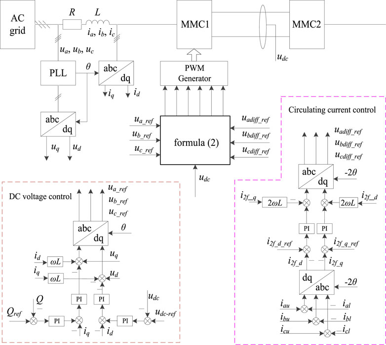
FIGURE 1. The control system of MMC.
As shown in Figure 1, ua, ub, and uc are the AC system voltage; ia, ib, and ic are the AC system current; θ is the phase angle of three-phase grid voltage; udc is the voltage of the DC bus; udc-ref is the voltage reference of the DC bus; ud and uq are the d-axis voltage and q-axis voltage, respectively; id and iq are the d-axis current and q-axis current, respectively; ua_ref, ub_ref, and uc_ref are the output midpoint voltage reference of the bridge arm; iau, ibu, and icu are the current flowing through the upper bridge arm; ial, ibl, and icl are the current flowing through the lower bridge arm; uadiff_ref, ubdiff_ref, and ucdiff_ref are the voltage drops of the bridge arm reactance, which are caused by a circulating current; uau_ref, ubu_ref, and ucu_ref are the voltage reference of the upper bridge arm; and ual_ref, ubl_ref, and ucl_ref are the voltage reference of the lower bridge arm.
L in Figure 1 is expressed as:
where Ls is the interface inductance between the MMC and grid, and Larm is the arm inductance.
The voltage references of the upper bridge arm and lower bridge arm are expressed as:
2.2 The theory of phase-locked loop
As shown in Figure 1, θ has an important influence on the control system of the MMC. The three-phase grid voltage is assumed as:
where Uh+ and Uh− are the amplitude of the positive-sequence component and negative-sequence component, respectively, θh+ and θh− are the phase angle of the positive-sequence component and negative-sequence component, respectively, h is the harmonic order, and ω1 is the angular frequency of the fundamental harmonic.
With the regard to the DC component, the PLL applies the moving average filter to eliminate its influence, and with regard to the even-order harmonic component, the amplitudes are much lower. Thus, (3) neglects the DC component and even-order harmonic component.
By applying the Clarke transformation, (3) can be expressed as:
By applying the Park transformation, (4) can be expressed as:
Once the output of PLL is
where f’ is the high-frequency disturbance.
Thus, the transfer function of the SRF-PLL with the first-order low-pass filter is expressed as:
where Kp and Ki are the proportional coefficient and integral coefficient, respectively, and Tlf is the time constant of the first-order low-pass filter.
According to (7), the bandwidth of the SRF-PLL is highly related with U1+. Thus, voltage sags will affect the stability of the SRF-PLL.
The SRF-PLL usually applies the PI controller instead of the filter. Thus, the dynamic speed of the SRF-PLL is relatively low. In (Golestan et al., 2014), the trap filter is applied to eliminate the specific-order harmonic, while its performance is insufficient to meet the time-varying three-phase grid. In (Golestan et al., 2015b; Hamed Hany et al., 2016), the second-order generalized integrator is applied in the PLL, which lacks the suppression of the DC component. Thus, the PLL will result in fundamental frequency oscillations and phase angle oscillations.
The transfer function of the moving average filter is expressed as:
(8) shows that the moving average filter is equivalent to an infinite number of cascaded trap filters. It can eliminate any integer-order harmonic component by setting the Tω. Furthermore, compared with the PID controller, trap filter, and second-order generalized integrator, the moving average filter is much easier to implement in software.
2.3 2DoFs-PID
The single degree of the freedom PID controller cannot meet the needs of both the tracking performance and anti-disturbance performance. Figure 2 shows a PLL with the 2DoFs-PID controller.
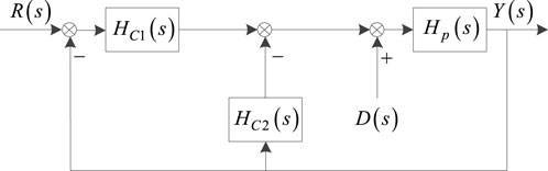
FIGURE 2. The PLL with the 2DoFs-PID.
As shown in Figure 2, HC1(s) is the transfer function of the PID controller in the feedback loop, and HC2(s) is the transfer function of the PID controller in the feed-forward loop. HC1(s) and HC2(s) are expressed as:
where KP, KI, and KD are the proportional coefficient, integral coefficient, and differential coefficient, respectively, and α and β are the coefficients of the two degrees of freedom.
As shown in Figure 2, the transfer function between the input signal and output signal is expressed as (10), and the transfer function between the disturbance signal and output signal is expressed as (11):
3 The operation performance of 2DoFs-PLL
3.1 The closed-loop transfer function
Figure 3 shows the structural schematic diagram of the 2DoFs-PLL with the moving average filter. In order to improve the performance of the tracking acceleration signal, an extra integrator is applied in the forward path. Thus, there are a total of three integrators in the improved 2DoFs-PLL.

FIGURE 3. Structural diagram of the 2DoFs-PLL.
Based on the internal model principle, the 2DoFs-PLL can track an acceleration signal without a structurally steady error.
The extra integrator results in a smaller phase margin, and the moving average filter introduces an additional pole, which will impact the stability of the 2DoFs-PLL. Thus, to eliminate the influence of the extra integrator and moving average filter, a compensator with a pole and a zero is introduced. Its transfer function is expressed as:
The structural diagram of the improved 2DoFs-PLL is shown in Figure 4.
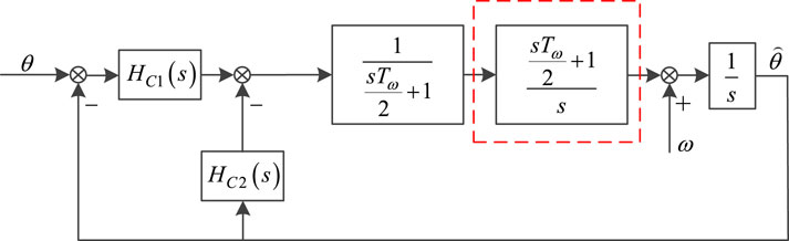
FIGURE 4. The transfer function of the improved 2DoFs-PLL.
Thus, the closed-loop transfer function of the improved 2DoFs-PLL is expressed as:
3.2 Parameters design method
Based on (14), if KP>0, KI>0 and KD>0 is satisfied, the improved 2DoFs-PLL is stable.
Moreover, according to (10) and (11), HC1(s) + HC2(s) is equivalent to the traditional PID controller. In terms of integrated time and absolute error, (13) should be expressed as:
where ω0 is the bandwidth of the PLL.
Thus, according to (13) and (15), KP, KI, and KD are achieved.
Then, based on the integrated time and absolute error and HYR(s), the parameters α and β are achieved.
3.3 The performance of improved 2DoFs-PLL
To verify the performance of the improved 2DoFs-PLL, a simulated model is built, and the parameters are shown in Table 1.
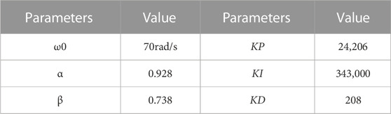
TABLE 1. Parameters of 2DoFs-PLL.
According to (13) and (14) and Table 1, the settling time is 0.03s, the gain margin is 26.5dB, and the phase angle margin is 54°.
Figure 5 shows the response diagrams of the disturbance signals and reference signals.
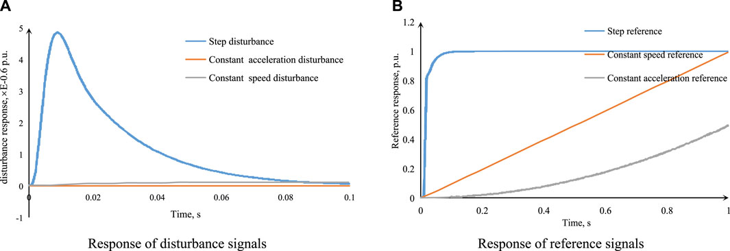
FIGURE 5. The responses performance of the improved 2DoFs-PLL. (A) The response of disturbance signals. (B) The response of reference signals.
As shown in Figure 5A, the improved 2DoFs-PLL can eliminate the influences of the disturbance signals on the output. The responses of the step disturbance signal, constant speed disturbance signal, and constant speed disturbance signal are relatively small. The unit step response is approximately equal to 5E-06. The responses of the constant speed disturbance signal and constant speed disturbance signal can even be ignored.
Furthermore, the improved 2DoFs-PLL shows a rapid responsibility of the step disturbance signal, constant speed disturbance signal, and constant speed disturbance signal. The decay time is about 0.06 s, which is equal to three power-frequency periods.
As shown in Figure 5B, the improved 2DoFs-PID can track the step reference, constant speed reference, and constant acceleration reference without the steady-state error, and for the step reference, the response is without overshoot.
4 Results
To verify the proposed improved 2DoFs-PLL, a simulation model is built. To facilitate comparison, the SRF-PLL orientates the phase angle of the three-phase grid voltage at the zero-crossing point of the voltage, and the improved 2DoFs-PLL orientates the phase angle of the three-phase grid voltage at the peak point of the voltage. Thus, compared with the improved 2DoFs-PLL, the output of the SRF-PLL is 90° ahead.
Figure 6A shows the output diagram under the condition that there is DC component in the three-phase voltage. Figure 6B shows the output diagram under the condition that there is a harmonic component and negative sequence component in the three-phase voltage. Figure 6C shows the output diagram under the condition that there is a phase jump in the three-phase voltage. Figure 6D shows the output diagram under the condition that there is a voltage amplitude jump and frequency jump in the three-phase voltage.
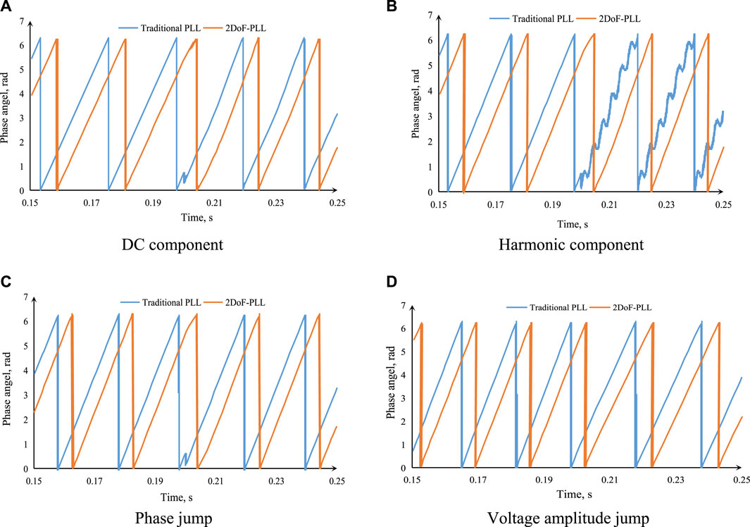
FIGURE 6. The response under different conditions. (A) The response under the condition of DC component. (B) The response under the condition of harmonic component. (C) The response under the condition of phase jump. (D) The response under the condition of voltage amplitude jump.
As shown in Figure 6A, the DC component is introduced into the three-phase voltage at 0.2 s. Both the SRF-PLL and improved 2DoFs-PLL can track the phase angle rapidly. Compared with the SRF-PLL, the dynamic response speed of the improved 2DoFs-PLL is relatively higher since it contains a differentiation element, and there is a slight distortion in the output of the SRF-PLL. Thus, in respect to the DC component, both the dynamic performance and steady performance of the improved 2DoFs-PLL are superior to that of the SRF-PLL.
As shown in Figure 6B, the harmonic component and negative sequence component are introduced into the three-phase voltage at 0.2 s. The response of the SRF-PLL contains an apparent distortion. Thus, the SRF-PLL cannot adapt to the grid with a harmonic component. Meanwhile, the improved 2DoFs-PLL can track the phase angle without the steady-state error, and its response speed is still high. Thus, in respect to the harmonic component and negative sequence component, both the dynamic performance and steady performance of the improved 2DoFs-PLL are superior to that of the SRF-PLL.
As shown in Figure 6C, the phase jump is introduced into the three-phase voltage at 0.2 s. The response speed of the improved 2DoFs-PLL is slightly slower than that of the SRF-PLL, and both PLLs can track the phase angle without the steady-state error.
As shown in Figure 6D, the voltage amplitude jump and frequency jump are introduced into the three-phase voltage at 0.2 s, and the frequency is from 50to 45 Hz. Both PLLs can track the phase angle without the steady-state error.
Thus, compared with the SRF-PLL, the improved 2DoFs-PLL can track the phase angle under severe conditions.
Figure 7 shows the output current of the MMC under the conditions that the three-phase grid voltage contains the harmonic component. Moreover, the number of SMs in each arm is 12, the DC bus voltage is 12 kV, the amplitude of AC voltage is
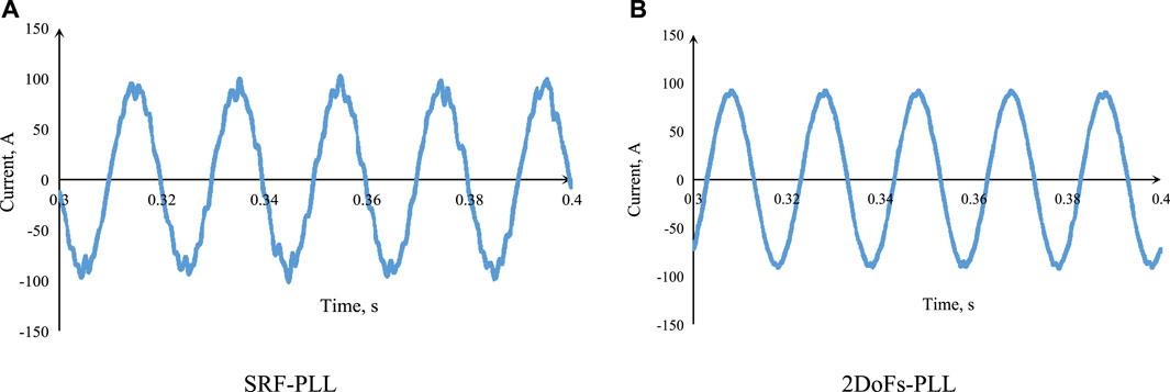
FIGURE 7. The output current of the MMC. (A) The output current with SRF-PLL. (B) The output current with 2DoFs-Pll.
As shown in Figure 7, the control system with the improved 2DoFs-PLL shows a superior performance to the SRF-PLL.
5 Conclusion
The 2DoFs-PID controllers can eliminate the influences of different disturbance signals and track different reference signals without the steady-state error. In order to improve the phase margin and gain margin and counteract the effects of the moving average filter, an extra compensator with a pole and a zero is introduced into the improved 2DoFs-PLL. Based on the index of integrated time and absolute error, the parameters are designed too.
The simulated results show that the output of the improved 2DoFs-PLL is almost equal to zero with the step disturbance, constant speed disturbance, and constant acceleration disturbance. Moreover, the improved 2DoFs-PLL can track the step reference, constant speed reference, and constant acceleration reference accurately and rapidly.
The results also show that the dynamic response speed of the improved 2DoFs-PLL is relatively high. It can track the frequency and phase angle without the steady-state error under the conditions of the DC component, harmonic component, negative sequence component, phase jump, frequency jump, and amplitude jump.
Data availability statement
The original contributions presented in the study are included in the article/Supplementary Material, further inquiries can be directed to the corresponding author.
Author contributions
Conceptualization, WW; methodology, WW, PW, and HC; software, PW and RB; validation, WW and HC; resources, WW and PW; data curation, HC, RB, and LG; writing—original draft preparation, WW and LG; writing—review and editing, WW, RB, and HC; supervision, WW and HC; funding acquisition, WW. All authors contributed to the article and approved the submitted version.
Conflict of interest
Authors WW, PW, and LG were employed by the Guangdong Power Grid Company; Author RB was employed by the company NR Electric Co., Ltd.
The remaining author declares that the research was conducted in the absence of any commercial or financial relationships that could be construed as a potential conflict of interest.
Publisher’s note
All claims expressed in this article are solely those of the authors and do not necessarily represent those of their affiliated organizations, or those of the publisher, the editors and the reviewers. Any product that may be evaluated in this article, or claim that may be made by its manufacturer, is not guaranteed or endorsed by the publisher.
References
Chauhan, A., and Saini, R. P. (2014). A review on integrated renewable energy system based power generation for stand-alone applications: Configurations, storage options, sizing methodologies and control. Renew. Sustain. Energy Rev. 38 (5), 99–120. doi:10.1016/j.rser.2014.05.079
Chen, S-Y., and Chang, C-H. (2023). Optimal power flows control for home energy management with renewable energy and energy storage systems. IEEE Trans. Energy Convers. 38 (1), 218–229. doi:10.1109/tec.2022.3198883
Errigo, F., Morel, F., Mathieu De Vienne, C., Chedot, L., Sari, A., and Venet, P. (2022). A submodule with integrated supercapacitors for HVDC-MMC providing fast frequency response. IEEE Trans. Power Deliv. 37 (3), 1423–1432. doi:10.1109/tpwrd.2021.3086864
Florian, H., Walter, S., and Lennart, H. (2017). Small-signal modeling of three-phase synchronous reference frame phase-locked loops. IEEE Trans. Power Electron. 33 (7), 5556–5560. doi:10.1109/tpel.2017.2783189
Golestan, S., Freijedo Francisco, D., Vidal, A., Guerrero, J. M., and Doval-Gandoy, J. (2014). A quasi-type-1 phase-locked loop structure. IEEE Trans. Power Electron. 29 (12), 6264–6270. doi:10.1109/tpel.2014.2329917
Golestan, S., Malek, R., Guerrero Josep, M., and Monfared, M. (2015a). dq Frame cascaded delayed signal cancellation- based PLL: Analysis, design, and comparison with moving average filter-based PLL. IEEE Trans. Power Electron. 30 (3), 1618–1632. doi:10.1109/tpel.2014.2315872
Golestan, S., Guerrero Josep, M., Vidal, A., Yepes, A. G., and Doval-Gandoy, J. (2015b). PLL with MAF-based prefiltering stage: Small-signal modeling and performance enhancement. IEEE Trans. Power Electron. 31 (6), 4013–4019. doi:10.1109/tpel.2015.2508882
Golestan, S., Guerrero, J. M., and Gharehpetian, G. B. (2016). Five approaches to deal with problem of DC offset in phase-locked loop algorithms: Design considerations and performance evaluations. IEEE Trans. Power Electron. 31 (1), 648–661. doi:10.1109/tpel.2015.2408113
Hamed Hany, A., Abdou Ahmed, F., Bayoumi Ehab, H. E., and El-Kholy, E. E. (2016). Frequency adaptive CDSC-PLL using Axis drift control under adverse grid condition. IEEE Trans. Industrial Electron. 64 (4), 2671–2682. doi:10.1109/TIE.2016.2633524
Liu, X., Grassi, F., Spadacini, G., and Pignari, S. (2020). Physically based modeling of hand-assembled wire bundles for accurate EMC prediction. IEEE Trans. Electromagn. Compat. 62 (3), 914–922. doi:10.1109/TEMC.2019.2922455
Liu, X., Xiong, L., Wu, B., Qian, Y., and Liu, Y. (2022a). Phase locked-loop with decaying DC transient removal for three-phase grids. Int. J. Electr. Power & Energy Syst. 143, 108508. doi:10.1016/j.ijepes.2022.108508
Liu, X., Wu, B., and Xiu, L. (2022b). A fast positive-sequence component extraction method with multiple disturbances in unbalanced conditions. IEEE Trans. Power Electron. 37 (8), 8820–8824. doi:10.1109/tpel.2022.3161734
Ming, L., Zhao, C., Li, Z., and He, J. (2021). Circuit dynamics analysis and control of the full-bridge five-branch modular multilevel converter for comprehensive power quality management of cophase railway power system. IEEE Trans. Industrial Electron. 69 (4), 3278–3291. doi:10.1109/tie.2021.3076720
Nami, A., LuisRodriguez-Amenedo, J., Santiago, A., Cardiel-Alvarez, M. A., and Baraciarte, R. A. (2022). Control of the parallel operation of DR-HVDC and VSC-HVDC for offshore wind power transmission. IEEE Trans. Power Deliv. 37 (3), 1682–1691. doi:10.1109/tpwrd.2021.3095529
Pedro, R., Josep, P., Joan, B., Candela, J. I., Burgos, R. P., Boroyev, D., et al. (2007). Decoupled double synchronous reference frame PLL for power converters control. IEEE Transaction Power Electron. 22, 585–592. doi:10.1109/TPEL.2006.890000
Reddy, G. A., and Shukla, A. (2021). Circulating current optimization control of MMC. IEEE Trans. Industrial Electron. 68 (4), 2798–2811. doi:10.1109/tie.2020.2977565
Shen, K., Zhao, D., Chen, L., Zhao, G., and Chen, W. (2020). A time-delayed filter based suppression method of circulating current in modular multilevel converters. IEEE Trans. Industrial Electron. 68 (10), 10309–10315. doi:10.1109/tie.2020.3026291
Wu, F., and Li, X. (2017). Multiple DSC filter-based three-phase EPLL for nonideal grid synchronization. IEEE J. Emerg. Sel. Top. Power Electron. 5 (3), 1396–1403. doi:10.1109/jestpe.2017.2701498
Xiong, L., Zhuo, F., Liu, X., Zhu, M., Chen, Y., and Wang, F. (2015). “Research on fast open-loop phase locking scheme for three-phase unbalanced grid,” in Proceeding of the 2015 IEEE Applied Power Electronics Conference and Exposition, Charlotte, NC, USA, March 2015 (IEEE), 1672–1676.
Keywords: modular multilevel converter (MMC), moving average filter, phase tracking, two degrees of freedom PID (2DoFs-PID), phase-locked loop (PLL)
Citation: Wenhong W, Wei P, Cencen H, Baiqun R and Guobing L (2023) The improved 2DoFs-PLL for MMC-HVDC transmission system. Front. Energy Res. 11:1206247. doi: 10.3389/fenrg.2023.1206247
Received: 15 April 2023; Accepted: 15 June 2023;
Published: 22 June 2023.
Edited by:
Xiaokang Liu, Polytechnic University of Milan, ItalyCopyright © 2023 Wenhong, Wei, Cencen, Baiqun and Guobing. This is an open-access article distributed under the terms of the Creative Commons Attribution License (CC BY). The use, distribution or reproduction in other forums is permitted, provided the original author(s) and the copyright owner(s) are credited and that the original publication in this journal is cited, in accordance with accepted academic practice. No use, distribution or reproduction is permitted which does not comply with these terms.
*Correspondence: Hong Cencen, aG9uZ2NlbmNlbmpqQDE2My5jb20=