 Chuansijia Tao
 Xin Du1*
 Xun Zhou
 Wenjuan Xu
- 1School of Energy Science and Engineering, Harbin Institute of Technology, Harbin, China
- 2Center for Turbulence Control, Harbin Institute of Technology, Shenzhen, China
Three-dimensional separation is an inherent flow feature in the blade-end corner of compressors passage, which is a primary source of entropy generation and loss. This paper researches the effect of key geometrical parameters (camber angle, solidity, dihedral angle of compound lean blade) and incoming condition (Mach number) on the evolution of corner separation in a low aspect ratio linear cascade. The underlying flow mechanism is explored in detail. The evolution of typical flow characteristics with the variation of inlet Mach number, camber angle and solidity is interpreted. For different blade loading levels, there are different corner separation forms and vortex structures. The influence of dihedral angle on the flow field structure and flow loss is analyzed, thus the effect mechanism of the compound lean blade in different flow environment is explored. Without the trailing edge shedding vortex, positive dihedral angle alleviates the low momentum fluid accumulation and corner separation at the incidence angle about 0°, but exacerbates the deteriorating corner separation at large positive incidence angle. When the trailing edge shedding vortex and the suction surface separating vortex exist together, positive dihedral angle promotes the upstream migration of the trailing edge shedding vortex, which helps to truncate the suction surface separating vortex. This variation of vortex structures is conducive to weaken the development of corner separation and delay corner stall.
1 Introduction
As the trend of compressor development is high loading and high efficiency, it’s required to increase the pressure ratio per stage and improve flow structure (Tang and Liu, 2020; Tang et al., 2020). With the blade tip speed constraints, enhancing loading per stage is a common method to obtain the pressure ratio per stage (Dickens and Day, 2011). With the low-reaction design, the rotor flow control strategy is simplified (Qiang et al., 2008; Sun et al., 2018; Sun et al., 2020; Sun et al., 2021), while the inlet Mach number and the static pressure rise of the stator are significantly increased (Sun et al., 2019; Zhang et al., 2019; Sun et al., 2022). Increasing Mach number enhances the compressibility and shear stress of the flow, which results in suction surface entropy generation, wake loss, and possibly boundary layer separation loss increasing rapidly. Moreover, the peak suction surface velocity will reach sonic conditions when inlet Mach number is about 0.7. The supersonic region is terminated by a normal shock in general, which leads to shock loss (Denton, 1993; Shi and Ji, 2021).
With the subsonic inflow, the main method to increase the static pressure rise of the stator is to increase the turning angle. As the blade loading and flow turning is raised, the pressure gradient transverse to the main flow direction enhances (Koller et al., 2000; Kusters et al., 2000; Song et al., 2002; Song et al., 2006; Song et al., 2008). This caused significant cross-passage flow, which transports low momentum fluid into the suction-hub corner region. The low momentum fluid accumulated in the corner region suffers adverse pressure gradient and forms three-dimensional separation, which is an inherent flow feature in the blade-end corner of compressors passage (Zheng et al., 2021; Tang et al., 2020). Large coverage of boundary layer separation and complicated disordered vortex structures significantly impair the stage efficiency (Ju et al., 2020; Li et al., 2020; Zhao et al., 2020; Hu et al., 2021; Vuong and Kim, 2021).
Solidity is one of the most significant geometrical parameters in preliminary design, which have remarkable impact on flow turning capacity, blade loading, and effective operating range (Howell, 1945; Zweifel, 1945; Carter, 1950; Lieblein et al., 1953). With pursuit of empirical solidity inputs in mean-line and through-flow design, performance prediction models containing solidity are necessary for multistage compressor. Bruna et al. (2006) chose inlet flow angle, inlet Mach number, AVDR, Reynolds number, and solidity as model parameters to study profile loss. Sans et al. (2014) updated the correlations for CDA blades. In our previous studies, the influence of maximum thickness position, solidity and camber angle on aerodynamic performance is quantitative assessed, and the optimal maximum thickness position matching solidity and camber angle is provided for high loading stator airfoil (Tao et al., 2021).
Compound lean blade, a kind of 3D stacking, is employed for controlling the corner separation and cutting down the flow losses since 1980s (Wang, 1981). The physical mechanism is that compound lean blade alters spanwise pressure gradient to off-load the endwall region relative to the mid-span section. Weingold et al. (1995) employed controlled diffusion airfoil (CDA) and compound lean stator in a 3-stage compressor. Experimental data verified the effectiveness of the compound lean stator in reducing corner separation and detailed the quantitative efficiency increment in a multistage environment. Gümmer et al. (2001) combined sweep and compound lean and applied this concept to the transonic compressor stators of the BR710 engine and published results. A three-dimensional Navier–Stokes code used for numerical assessment demonstrated that the low momentum fluid near endwall tends to be transported toward mid-span, enhancing the radial mixing process. Nowadays, compound lean blade was associated with other flow control methods, such as boundary layer suction (Song et al., 2006; Ding et al., 2018), vortex generator jet (Li et al., 2016; Li et al., 2017), and non-axisymmetric endwall (Lin et al., 2014). To reveal the universal application conditions of compound lean blade, Xu and Du et al. established performance characteristics prediction models for the compound lean blade and presented the interaction of solidity, aspect ratio and dihedral angle in NACA65 compressor cascade (Xu et al., 2019; Xu et al., 2018). Due to flow complexity, high experimental costs and reducing sharply effective operating range with the increment of Mach number, the systematic investigation on the application conditions of compound lean blade are lacking and worthy of attention in high subsonic flow circumstance.
In this paper, the numerical calculation carried out in abundant low aspect ratio linear cascades has been applied to explore the effect of key geometrical parameters and incoming condition on the evolution of corner separation mechanism. The flow phenomenon in cascades with five camber angles, nine solidities and six dihedral angles is compared under two different incoming flow conditions of medium subsonic (Ma = 0.5) and high subsonic (Ma = 0.8). The underlying pressure fields and vortex structures are revealed subsequently. The typical flow evolution brought by the high subsonic inlet and the high loading blade is observed and explained. For the deteriorated corner separation under high subsonic inlet conditions, the compound lean blade is applied to control the flow field and corner separation. The development law of the flow field with dihedral angle of compound lean blade is discussed in different flow environments. The current research is launched in order to acquire a better understanding of the flow mechanism in high loading cascades, and is of great significance to the guidance of compound lean blade application.
2 Investigation programs and numerical method
2.1 Investigation programs
The investigated cascades are used for the second stage stator of a 3-stage compressor. The airfoil features CDA velocity distribution. The investigation about the selected airfoil has been detailed in reference (Tao et al., 2021). Geometrical parameters are shown in Table 1. The straight blade refers to α = 0°. Maximum thickness is normalized by chord length. The research ranges cover the usually used values in high subsonic cascade applications. The geometric parameters of airfoil geometry are presented in Supplementary Figure S1.
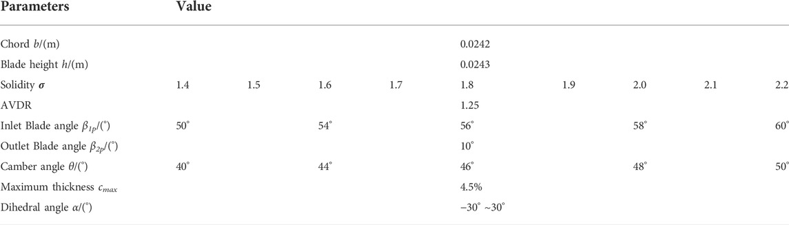
TABLE 1. Parameters and flow conditions of research.
The stacking line of compound lean blade is perpendicular to the chord length direction, consisting of a straight line at mid-span and two Bezier curves in endwall region. The schematic diagram of stacking line is shown in Supplementary Figure S1B, where P1 and P2 are the dimensionless control parameters of Bezier curves. The parameters C1 and C2 are the compound lean height. According to the results of reference (Ling et al., 2014), the total pressure loss is the lowest when compound lean height is 50% blade height in linear cascade. Therefore, the compound lean height is selected as 50%h in this paper. The parameters α1 and α2 are the dihedral angle at hub and shroud respectively. As the stacking line is symmetrical in linear cascade, P1 = P2, C1 = C2, α1 = α2.
2.2 Numerical method and validation
The NUMECA IGG/AutoGrid5 module is applied for structured grids generation (NUMECA International, 2015). The computation domain mesh has a mixed O-and H-block topology, as shown in Supplementary Figure S2. The inlet and outlet of the computational domain are located 100%b ahead of the leading-edge and 100%b behind the trailing-edge, respectively. The measurement plane is located 40%b behind the trailing-edge. The thickness of the first grid layer is 10−6 m, and 5 m × 10−6 m near the hub and shroud, to insure y+ <3 at solid boundary and satisfy the solving demands of the selected turbulence model.
The grid independence investigation is carried out including six meshes with 0.6–2.2 million cells. As shown in Supplementary Figure S3, when further refining the mesh with grids number beyond 1.97 million, the results almost have no modification. The spanwise distribution of total pressure loss coefficient and deviation angle of different meshes is drawn in Supplementary Figure S4. When the number of grids is above 1.65 million, the spanwise distribution of total pressure loss coefficient and deviation angle varies with the number of grids not significantly. Therefore, the spanwise node number adopted is 73 in this study, and the total grids number is about 1.97 million.
The code solver ANSYS CFX™ is used to solve the Reynolds-Averaged Navier-Stokes (RANS) equations with the finite volume technique. The equations governing the flow domain are written in a tensor form as follows:
where the stress tensor τ, is related to the strain rate by the constitutive equation of the Newtonian fluid as follows:
A high-resolution scheme was used for the advection scheme and turbulence modeling. The two-equation turbulence models SST coupled with γ-Reθ transition model was finally chosen for its capability to accurately predict complex flows Average
Inlet boundary conditions are prescribed with total pressure (430 kPa), total temperature (440 K) and inflow angle. No-slip and adiabatic conditions are imposed at the solid walls, while translational periodic boundary condition is used in the pitchwise direction. The mass-flow specified at the outlet is modified to achieve Ma = 0.8 at the inlet. Non-reflecting boundary conditions are used at inlet/outlet planes.
The MOGA profile in literature (Song and Ng, 2006; Song et al., 2006) is selected to validate the calculation methods. Inlet total pressure is 121 kPa, while total temperature is 319 K. The inflow angle is 48.4°. No-slip and adiabatic conditions are imposed at the solid walls, while translational periodic boundary condition is used in the pitchwise direction. The Mach number at the inlet is 0.6–0.95, which includes the Mach number of this research. The comparison between experimental and numerical results at different incoming Mach number is shown in Supplementary Figure S5. It can be seen that the trend of numerical simulation is basically consistent with experiments. The error of losses between numerical simulation and experiments is about 5%–10% and due to the combined effects of CFD under-prediction and AVDR influence.
3 Results discussion
3.1 Effect of mach number on the straight cascades
3.1.1 Performance parameters changing with incidence angle
In order to evaluate the effect of Ma on the straight cascades quantitatively, Supplementary Figure S6 shows the performance parameters (total pressure loss coefficient ω and diffusion factor D) at different incidence angles. The mass-averaged total pressure loss coefficient and diffusion factor are determined as follows:
where,
When the camber angle increases, ω and D gradually increase, while the effective operating range gradually narrows. As the Mach number increases from 0.5 to 0.8, ω and D continue to increase, while the effective operating range gradually narrows further. Under high subsonic condition, the effective operating range is less than 1° when camber angle is 50°. By exploring the change of flow with camber angle and Mach number, it is possible to search for methods to maintain a steady working range and to improve the overall performance of high loading cascade.
3.1.2 Distribution of performance parameters
In order to detect in more detail how Ma variation affects the distribution of loss, spanwise distribution of total pressure loss coefficient under different Ma and θ at i = 0.5°are compared in Supplementary Figure S7. It is observed that the rise of camber angle and inlet Mach number increases both the loss near the endwall and the mid-span loss, while the loss near the endwall increases more significantly. This observation means that the coverage of the region affected by the endwall cross-passage flow and the low momentum fluid accumulated in the corner region tends to expand with the increase of Ma and θ. On the other hand, the increase of Ma and θ enhances the shear stress of the flow, resulting in the entropy generation of the blade.
The variation of axial distribution of surface static pressure coefficient not only reflects the load distribution at different spanwise positions, but also determines the development of boundary layer. The axial distribution of surface static pressure coefficient varies with Ma and θ at i = 0.5° are presented in Supplementary Figure S8. It shows that the rise of Ma and θ will increase not only the pressure difference between the suction surface and pressure surface, but also the streamwise adverse pressure gradient on the suction surface and pressure surface. The increase of the pressure difference between the suction surface and pressure surface promotes the endwall cross-passage flow, which intensifies the accumulation of low momentum fluid in the corner region. The low momentum fluid in the corner region suffers enhanced streamwise adverse pressure gradient, which results in more complex boundary layer separation. These lead to significant growth of endwall loss.
3.1.3 Evolution of 3D corner separation flow
In order to reveal the separation mechanism leading to the loss variation, comparisons of the three-dimensional corner separation structures are made in more detail. Supplementary Figures S9–S12 depicts the radial pressure gradient and surface limiting streamlines on the suction surface, the transverse pressure gradient and surface limiting streamlines on the endwall, as well as the distribution of total pressure loss coefficient across the trailing edge when camber angle is 40°–48°. Through these figures, the evolution of flow separation with the increase of camber angle, Mach number and incidence angle can be observed.
At Ma = 0.5, the corner separation is not serious when camber angle is 40° (as shown in Supplementary Figures S9A,C,E,G,1). With the increase of incidence angle, the trend of the surface limiting streamlines on suction surface converging to the mid-span intensifies. The onset of the separation migrates forward as the incidence angle increases. At the incidence angle of 4°, small reverse flow of the suction-hub corner region begins to appear near the trailing edge (as shown in Supplementary Figure S9G). The coverage of the corner separation and the reverse flow expand with the growth of incidence angle, which results in the rise of loss in suction-hub corner region.
The increase of camber angle leads to the intensification of the convergence trend of suction surface limiting streamlines, as well as the expansion of the coverage of corner separation and reverse flow. At the incidence angle of 0°, small reverse flow of the suction-hub corner region occurs near the trailing edge when camber angle is 44° (as shown in Supplementary Figure S10C). For camber angles of 46° and 48°, the reverse flow exists at all incidence angles (as shown in Supplementary Figures S11, S12). When the incidence angle exceeds 4.5°, the corner separation almost extends to the mid-span (as shown in Supplementary Figure S12I). As a result, the high loss area of the end region across the trailing edge almost extends to mid-span, while the loss increased sharply.
When the Mach number rises to 0.8, both the transverse pressure gradient of the endwall and the radial pressure gradient of the suction surface increase (as shown in Supplementary Figures S9B,D,F,H,J). The varied pressure gradient field enhances the trend of the suction surface limiting streamlines converging to the mid-span of the blade. The form of corner separation maintains, while the coverage of the corner separation and the reverse flow expand, especially under the condition of large positive incidence angle. Reverse flow of the suction-hub corner region begins to appear earlier than Ma = 0.5. Expanded corner separation and reverse flow results in the growth of endwall loss and the narrowing of the effective operating range under high subsonic inlet condition.
Supplementary Figure S13 depicts the radial pressure gradient and surface limiting streamlines on the pressure surface, the transverse pressure gradient and surface limiting streamlines on the endwall, and the distribution of total pressure loss coefficient across the trailing edge when camber angle is 40°–48°. With the growth of camber angle, the radial pressure gradient on the pressure surface rises gradually, which is more significant at the incidence angle of −0.5° than 0°. Enhanced by higher radial pressure gradient, the limiting streamlines of the pressure surface converge towards the mid-span. The pressure surface separation of the mid-span occurs at the camber angle of 48° even (as shown in Supplementary Figures S13G,H). Large separation coverage leads to the sharply rise of the loss at the mid-span of pressure surface, especially at large negative incidence angle (as shown in Supplementary Figure S13G). Therefore, the available working range of negative incidence angle gradually narrows with the increase of camber angle.
Supplementary Figures S14, S15 depict the flow fields of suction surface and pressure surface respectively at θ = 50°. Impacted by higher radial pressure gradient, the corner separation almost extends to the mid-span, especially at Ma = 0.8. Moreover, the mid-span separation occurs near the trailing edge, resulting in the growth of mid-span loss. Due to the interaction of corner separation and mid-span trailing edge separation on the suction surface, the flow structure deteriorates and the corner stall is more easily to occur. The minimum loss incidence angle is the critical incidence angle. When the incidence angle continues to increase by 0.1°, it will cause the interaction between corner separation on both sides (expansion on one side and suppression on the other side, as shown in Supplementary Figure S14J). Corner stall will lead to a sharp increase of the total pressure loss and a decrease in the diffuser factor, which can be observed in Supplementary Figure S6.
It can be reflected in Supplementary Figure S15 that large-scale separation occurs at the mid-span of pressure surface at Ma = 0.8, which causes the loss of the mid-span on the pressure side to enhance (as shown in Supplementary Figures S15B,D,F,H,J). This phenomenon gradually improves with the increase of the incidence angle. With the suction-hub corner stall and the narrow effective operating range, the large-scale separation at the mid-span of the pressure surface exists from surge to stall.
Research above illustrates that the increase of Mach number and camber angle not only increase the blade loading, but also aggravate the corner separation of suction surface, especially in the cascade with a camber angle of 50° under the condition of high subsonic flow. Under the condition of high subsonic inlet, the effect of flow control on the typical flow phenomena is worth studying in high-loaded cascades.
3.2 Effect of dihedral angle on high-loaded cascade
Because compound lean blade alters spanwise pressure gradient to off-load the endwall region, it is applied to affect the flow in high loading cascades. We provide the evaluation of dihedral angle action in high-loaded cascades under high subsonic inlet conditions systematically.
3.2.1 Performance parameters changing with incidence angle
Supplementary Figure S16 shows the incidence characteristics of both straight blade and compound lean blade with different camber angels and solidities at Ma = 0.8. With the increase of solidity, the incidence characteristics of total pressure loss coefficient move upper right, and the characteristics of diffusion factor moves towards the right. When the camber angle is 40°–48°, the effective operating ranges of compound lean blades are narrower than straight blades. It is worth noting that positive dihedral angle widens the effective operating ranges in cascades with a camber angle of 50°.
3.2.2 Effect of solidity on blade loading
Focusing on the straight blade with a camber angle of 44°, it is discussed why the incidence characteristics of total pressure loss coefficient move towards the right with the growth of solidity. The axial distribution of surface static pressure coefficient varies with solidity are depicted in Supplementary Figure S17. It can be observed that the blade loading decreases with the growth of solidity, while the distribution of surface static pressure coefficient at mid-span gradually assumes the characteristics of negative attack angle. The reason is that the throat width and the throat location vary due to the change of the solidity, resulting in the variation of the relative shrinking degree of the passage. Therefore, the fluid near the leading edge twists, and the attack angle acting on the leading edge is different from the incidence angle.
Supplementary Figure S18 depicts the effect of solidity on the flow fields of suction surface at θ = 44°. As the increase of solidity reduces the blade loading, the transverse pressure gradient on the endwall decreases. The low momentum fluid accumulation in the corner is weakened, while the coverage of corner separation and reverse flow shrinks. This leads to the reduction of end loss. In addition, the reduced blade loading is also effective to control the thickening of the boundary layer, which reduces the loss at the mid-span. By combining the limiting streamlines and the distribution of surface static pressure coefficient, it can be found that the effect of increasing the solidity on the flow is similar to the negative incidence angle. This results in the migration towards the right of the incidence characteristics of total pressure loss coefficient with the increase of solidity.
3.2.3 Flow in cascades with normal camber angle
In order to evaluate the effect of compound lean blades on corner separation, the comparison of incidence characteristics among different dihedral angles with the camber angle of 40°–48° is given in Supplementary Figure S19. The positive dihedral angles reduce the total pressure loss at small incidence angle, but increase the loss under the condition of large positive incidence angle. At θ = 44°, the incidence characteristics of two negative dihedral angles are depicted moreover. The effect of negative dihedral angle on the incidence characteristics is opposite to that of positive dihedral angle.
In the cascade with the camber angle of 40°, the total pressure loss is mainly caused by the corner separation of the suction surface, so the influence of dihedral angle on the flow of the suction surface is explored. Supplementary Figure S20 depicts the effect of dihedral angle on the flow fields of suction surface at three different incidence angles. The increase of dihedral angle will increase the radial pressure gradient, which propels the suction surface limiting streamlines to converge towards the mid-span more dramatically. At the incidence angle of 4°, the limiting streamlines on the suction surface converges to the mid-span significantly, while the corner separation coverage of straight blades expands (as shown in Supplementary Figure S20C). Therefore, the effect of dihedral angle on corner separation is more significant at large positive incidence angles.
To compare the effect of positive and negative dihedral angle on the corner separation, the cascades with the camber angle of 44° is investigated. Influence of the dihedral angle on the spanwise distribution of total pressure loss coefficient across the trailing edge at three different incidence angles are shown in Supplementary Figure S21. At the incidence angle of 0°, positive dihedral angle reduces the end loss. At the incidence angle of 2° and 4°, positive dihedral angle increases the end loss and enlarges the high loss region near the endwall. The effect of negative dihedral angle on end loss is opposite to that of positive dihedral angle. In addition, under the incidence angle of 0°, the positive dihedral angle will also cause the loss of mid-span to increase. As a result, the total pressure loss coefficient at this incidence angle is not significantly reduced by positive dihedral angle, which is reflected in Supplementary Figure S19.
Since compound lean blade mainly alters the pressure gradient near the endwall, Supplementary Figure S22 shows the axial distribution of surface static pressure coefficient at 95% relative height position with different dihedral angles. The axial location of the lowest pressure on the suction surface moves forward when the dihedral angle is 30°, while the adverse pressure gradient of the suction surface reduces near the endwall. Moreover, positive dihedral angle increases the attack angle acting on the leading edge. The effect of negative dihedral angle on the pressure gradient near the endwall is opposite to that of positive dihedral angle.
Supplementary Figure S23 draws the flow fields on suction surface of the blades with a camber angle of 44° at three different incidence angles. The positive dihedral angle increases the radial pressure gradient of the suction surface, which promotes the low momentum fluid in the corner region to the mid-span. This intensifies the trend of the suction surface limiting streamlines converging towards the mid-span (as shown in Supplementary Figures S23J,K,L). Negative dihedral angle has the opposite effect. At the incidence angle of 0°, the reverse flow near the trailing edge is small, and the positive dihedral angle reduces its size (as shown in Supplementary Figures S23G,J). At the incidence angle of 4°, the reverse flow near the trailing edge of the straight blade is large and close to the mid-span (as shown in Supplementary Figure S23I). The positive dihedral angle fails to limit the reverse flow to a small range, resulting in high local loss (as shown in Supplementary Figure S23L). The negative dihedral angle weakens the tendency of the limiting streamlines converging to the mid-span, and limits the reverse flow near the trailing edge to a small spanwise range (as shown in Supplementary Figures S23C,F).
In order to detect the location of vortex core in the corner separation region, the vortex identification Q criterion is used, which is defined as follows:
where, Ωij is the vorticity tensor; Sij is the shear strain tensor. Q represents the local balance between the shear strain rate and vorticity magnitude (Chakraborty et al., 2005). When Q decreases, vortex structures can be captured completely. However, if Q is too low, too many broken small vortex will be captured. Therefore, the vortex structures in the cascade can be completely and clearly observed only by properly selecting the Q. Supplementary Figure S24 provides the comparison of vortex structures identified by the iso-surface of Q = 5,000 between straight blade and compound lean blade with the dihedral angle of 30° at the incidence angle of 0°. For the straight blade, the pressure leg of horseshoe vortex (HPV) develops and migrates towards the suction surface of adjacent blades. The passage vortex (PV) and the separating vortex on suction surface (SSV) grow and expand, until SSV covers PV. The SSV continues to develop and gradually separates from the solid wall, forming a lamellar separation vortex, whose boundary on suction surface is the corner separation line. The reverse flow is stuck between the lamellar separation and the suction surface. The SSV and reverse flow are the main sources of loss in the whole cascade.
As compound lean blade increases the radial pressure gradient, more low momentum fluid in the corner region is squeezed towards the mid-span, and HPV merges with the PV of adjacent blades later. The PV and the layered SSV form earlier than that in the straight cascade. The two vortexes merge with each other to form a large suction surface corner separation. The reverse flow between the suction surface and SSV is smaller than that of straight cascade, which effectively reduces the end loss.
Supplementary Figure S25 depicts the vortex structures identified by the iso-surface of Q criterion of straight blade and compound lean blade with the dihedral angle of 30° at the incidence angle of 4°. At the incidence angle of 4°, the evolution of each vortex structure is similar to that at the incidence angle of 0°, but their size is larger than 0°, especially the SSV. For the compound lean blade with a dihedral angle of 30°, the SSV is significant at 10% relative axial chord location. Moreover, complex separation structures exist near the trailing edge. The above two aspects result in the increase of the loss of compound lean blade with a dihedral angle of 30°.
Supplementary Figure S26 illustrates the flow fields on suction surface of the blades with a camber angle of 48°. The effect of dihedral angle on the flow fields of suction surface is similar to Supplementary Figures S20, S23. Near the incidence of 0°, the positive dihedral angle reduces the total pressure loss effectively, because the positive dihedral angle shrinks the reverse flow. However, when the incidence angle is large, the positive dihedral angle increases the actual attack angle acting on the leading edge near the endwall. The reverse flow near the trailing edge extends to the mid-span, which leads to the end loss and the overall loss increase at the same time (as shown in Supplementary Figures S26F,I,L).
3.2.4 Flow in high-loaded cascades
The effect of compound lean blades is the most significant when the camber angle is 50°. Incidence characteristics with different dihedral angles for the camber angle of 50° are given in Supplementary Figure S27. Positive dihedral angle not only reduces the total pressure loss at the minimum loss incidence angle, but also widens the effective operating range to 2°, although that is less than 1° of straight blade.
The spanwise distribution of total pressure loss coefficient across the trailing edge at the incidence angle of 0.5° is shown in Supplementary Figure S28. Positive dihedral angle reduces the end loss and increases the loss of mid-span simultaneously.
Supplementary Figure S29 shows the flow fields on suction surface with θ = 50° at five different incidence angles. The trailing edge separation line expands towards the leading edge with the increase of dihedral angle, and the loss at the mid-span of suction surface increases correspondingly. The separation line of corner separation is “cut off” by the trailing edge separation line. So the corner separation line cannot continue to expand towards the mid-span, which expands to the mid-span in the straight cascade originally. It is the reason why positive dihedral angle reduces the end loss. This flow phenomenon can also be observed through the 3D streamlines depicted in Supplementary Figure S30.
Supplementary Figure S31 shows the flow fields on pressure surface with θ = 50°. There are large-scale limiting streamlines entrainment and spiral points at the mid-span of the pressure surface, as well as a high loss area at the pressure surface across the trailing edge correspondingly. The large-scale separation and high loss region expand with the rise of positive dihedral angle.
Comparison of vortex structures between straight blade and compound lean blade with the dihedral angle of 30° at the incidence angle of 0.5° is provided in Supplementary Figure S32. Different from the vortex structures in the cascade with a camber angle of 44°, an obvious trailing edge shedding vortex (TESV) near the trailing edge of the suction surface and a large-scale concentrated shedding vortex (CSV) at the mid-span of the pressure surface can be observed. As the TESV restricts the spanwise development of the SSV, the TESV of the positive dihedral angle of 30° expands upstream and limits the SSV in a small area. As the corner separation is limited, corner stall is effectively delayed, which is the reason for widening the effective operating range. Moreover, positive dihedral angle pushes the fluid near the endwall to the mid-span, which enlarges the CSV and causes more loss at the mid-span of pressure surface.
It can be concluded from above analysis that the effect of solidity on corner separation is linear. Different from solidity, the influence of dihedral angle on corner separation depends on the vortex structures. When only the SSV exists but the TESV doesn’t, the positive dihedral angle intensifies the convergence of the limiting streamlines to the mid-span on the suction surface. At the incidence angle about 0°, the coverage of the corner separation and reverse flow is small, when the positive dihedral angle squeeze more fluid near the endwall into the mid-span. This helps to alleviate the low momentum fluid accumulation and corner separation, and reduce the endwall loss. At large positive incidence angle, the corner separation extends to the mid-span. At this time, the positive dihedral angle fails to control the corner separation and reverse flow in a small range, which result in increasing endwall loss. When the TESV and the SSV exist together, the positive dihedral angle makes the TESV move upstream. This helps to truncate the SSV in advance, which result in controlling the further development of corner separation and delaying corner stall. Therefore, the endwall loss is effectively reduced and the available positive operating range is widened
4 Conclusion
The effect of key geometrical parameters (camber angle, solidity, dihedral angle) and incoming condition (inlet Mach number) on the evolution mechanism of the 3D corner separation has been investigated in a linear compressor cascade with low aspect ratio. The main conclusions are as follows:
1) Although the increase of Mach number and camber angle increases the blade loading, it also aggravates the low momentum fluid accumulation and suction-hub corner separation. Especially in the cascade with a camber angle of 50° under high subsonic inlet condition, the rapidly deteriorating corner separation reduces the effective operating range to less than 1°.
2) With the growth of solidity, the blade loading decreases and the surface static pressure distribution assumes the characteristics of negative attack angle acting on the leading edge. The accumulation of low momentum fluid is weakened, as well as the coverage of corner separation and reverse flow. Because the effect of increasing the solidity on the flow is similar to the negative incidence angle, the incidence characteristics of total pressure loss coefficient migrate towards the right.
3) Positive dihedral angle reduces the adverse pressure gradient of the suction surface near the endwall, increases the attack angle and the radial pressure gradient of the suction surface. The variation of pressure field promotes the low momentum fluid in the corner region to the mid-span. At the incidence angle about 0° without the TESV, positive dihedral angle alleviates the low momentum fluid accumulation and corner separation, and reduces the endwall loss. When the incidence angle is large and positive, the corner separation extends towards the mid-span. At this time, the positive dihedral angle exacerbates the deteriorating corner separation, which results in increasing endwall loss. The effect of negative dihedral angle on the flow field is opposite to that of positive dihedral angle.
4) When the TESV and the SSV exist together, positive dihedral angle promotes the upstream migration of the TESV, which helps to truncate the SSV. This variation of vortex structures helps to weaken the development of corner separation and delay corner stall. Therefore, positive dihedral angle effectively reduces the endwall loss and widens the effective operating range from less than 1°–2°.
Data availability statement
The original contributions presented in the study are included in the article/Supplementary Material, further inquiries can be directed to the corresponding author.
Author contributions
CT provides innovation, numerical simulation experiment, results discussion and writing for this article. XD provides financial support and guidance about the content of the article. XZ, SW, and ZW provide financial support. WX provides guidance about the content and some technical work. YL has engaged in some technical work.
Funding
This research is supported by the National Natural Science Foundation of China (Grant No. 51906049) and the National Science and Technology Major Project (2017-II-0007-0021).
Conflict of interest
The authors declare that the research was conducted in the absence of any commercial or financial relationships that could be construed as a potential conflict of interest.
Publisher’s note
All claims expressed in this article are solely those of the authors and do not necessarily represent those of their affiliated organizations, or those of the publisher, the editors and the reviewers. Any product that may be evaluated in this article, or claim that may be made by its manufacturer, is not guaranteed or endorsed by the publisher.
Supplementary material
The Supplementary Material for this article can be found online at: https://www.frontiersin.org/articles/10.3389/fenrg.2022.974508/full#supplementary-material
SUPPLEMENTARY FIGURE S1 | (A) Geometric parameters of airfoil geometry (B) Stacking line of compound lean blade.
SUPPLEMENTARY FIGURE S2 | Configuration of calculation mesh grids (A) Grids diagram; (B) Mesh grids at the leading edge; (C) Mesh grids at the trailing edge.
SUPPLEMENTARY FIGURE S3 | Effect of grid points number on the loss and deviation angle (A) Total pressure loss coefficient; (B) Deviation angle.
SUPPLEMENTARY FIGURE S4 | Effect of grid points number on the spanwise distribution of loss and deviation angle (A) Total pressure loss coefficient; (B) Deviation angle.
SUPPLEMENTARY FIGURE S5 | Variation of total pressure loss coefficient at outlet with incoming Mach number and axial isentropic Mach number distribution at the inlet Mach number of 0.77 (A) Variation of total pressure loss coefficient at outlet with incoming Mach number; (B) Axial distribution of isentropic Mach number at the inlet Mach number of 0.77.
SUPPLEMENTARY FIGURE S6 | Influence of Mach number on incidence characteristics of total pressure loss coefficient and diffusion factor with different camber angels (h/b = 1, σ = 1.8) (A) Total pressure loss coefficient; (B) Diffusion factor.
SUPPLEMENTARY FIGURE S7 | Spanwise distribution of total pressure loss coefficient at the measure plane under different Mach numbers and camber angels (h/b = 1, σ = 1.8, i = 0.5°).
SUPPLEMENTARY FIGURE S8 | Axial distribution of surface static pressure coefficient at 70% and 95% relative height position under different Mach numbers and camber angels (h/b = 1, σ = 1.8, i = 0.5°) (A) 70% relative height position; (B) 95% relative height position.
SUPPLEMENTARY FIGURE S9 | Radial pressure gradient and surface limiting streamlines on the suction surface, transverse pressure gradient and surface limiting streamlines on the endwall, and the distribution of total pressure loss coefficient across the trailing edge (h/b = 1, σ = 1.8, θ = 40°) (A) i = −1.5°, Ma = 0.5; (B) i = -1.5°, Ma = 0.8; (C) i = 0°, Ma = 0.5; (D) i = 0°, Ma = 0.8; (E) i = 2°, Ma = 0.5; (F) i = 2°, Ma = 0.8; (G) i = 4°, Ma = 0.5; (H) i = 4°, Ma = 0.8; (I) i = 6°, Ma = 0.5; (J) i = 6°, Ma = 0.8.
SUPPLEMENTARY FIGURE S10 | Radial pressure gradient and surface limiting streamlines on the suction surface, transverse pressure gradient and surface limiting streamlines on the endwall, and the distribution of total pressure loss coefficient across the trailing edge (h/b = 1, σ = 1.8, θ = 44°) (A) i = −1°, Ma = 0.5; (B) i = -1°, Ma = 0.8; (C) i = 0°, Ma = 0.5; (D) i = 0°, Ma = 0.8; (E) i = 2°, Ma = 0.5; (F) i = 2°, Ma = 0.8; (G) i = 4°, Ma = 0.5; (H) i = 4°, Ma = 0.8; (I) i = 5°, Ma = 0.5; (J) i = 5°, Ma = 0.8.
SUPPLEMENTARY FIGURE S11 | Radial pressure gradient and surface limiting streamlines on the suction surface, transverse pressure gradient and surface limiting streamlines on the endwall, and the distribution of total pressure loss coefficient across the trailing edge (h/b = 1, σ = 1.8, θ = 46°) (A) i = −0.5°, Ma = 0.5; (B) i = −0.5°, Ma = 0.8; (C) i = 0°, Ma = 0.5; (D) i = 0°, Ma = 0.8; (E) i = 2°, Ma = 0.5; (F) i = 2°, Ma = 0.8; (G) i = 4°, Ma = 0.5; (H) i = 4°, Ma = 0.8; (I) i = 5°, Ma = 0.5; (J) i = 5°, Ma = 0.8.
SUPPLEMENTARY FIGURE S12 | Radial pressure gradient and surface limiting streamlines on the suction surface, transverse pressure gradient and surface limiting streamlines on the endwall, and the distribution of total pressure loss coefficient across the trailing edge (h/b = 1, σ = 1.8, θ = 48°) (A) i = −0.5°, Ma = 0.5; (B) i = −0.5°, Ma = 0.8; (C) i = 0°, Ma = 0.5; (D) i = 0°, Ma = 0.8; (E) i = 2°, Ma = 0.5; (F) i = 2°, Ma = 0.8; (G) i = 4°, Ma = 0.5; (H) i = 4°, Ma = 0.8; (I) i = 4.5°, Ma = 0.5; (J) i = 4.5°, Ma = 0.8.
SUPPLEMENTARY FIGURE S13 | Radial pressure gradient and surface limiting streamlines on the pressure surface, transverse pressure gradient and surface limiting streamlines on the endwall, and the distribution of total pressure loss coefficient across the trailing edge (h/b = 1, σ = 1.8, Ma = 0.8) (A) θ = 40°, i = −0.5°; (B) θ = 40°, i = 0°; (C) θ = 44°, i = −0.5°; (D) θ = 44°, i = 0°; (E) θ = 46°, i = −0.5°; (F) θ = 46°, i = 0°; (G) θ = 48°, i = −0.5°; (H) θ = 48°, i = 0°.
SUPPLEMENTARY FIGURE S14 | Radial pressure gradient and surface limiting streamlines on the suction surface, transverse pressure gradient and surface limiting streamlines on the endwall, and the distribution of total pressure loss coefficient across the trailing edge (h/b = 1, σ = 1.8, (A) θ = 50°) i = 0°, Ma = 0.5; (B) i = 0°, Ma = 0.8; (C) i = 0.1°, Ma = 0.5; (D) i = 0.1°, Ma = 0.8; (E) i = 0.25°, Ma = 0.5; (F) i = 0.25°, Ma = 0.8; (G) i = 0.5°, Ma = 0.5; (H) i = 0.5°, Ma = 0.8; (I) i = 0.7°, Ma = 0.5; (J) i = 0.7°, Ma = 0.8.
SUPPLEMENTARY FIGURE S15 | Radial pressure gradient and surface limiting streamlines on the pressure surface, transverse pressure gradient and surface limiting streamlines on the endwall, and the distribution of total pressure loss coefficient across the trailing edge (h/b = 1, σ = 1.8, θ = 50°) (A) i = 0°, Ma = 0.5; (B) i = 0°, Ma = 0.8; (C) i = 0.1°, Ma = 0.5; (D) i = 0.1°, Ma = 0.8; (E) i = 0.25°, Ma = 0.5; (F) i = 0.25°, Ma = 0.8; (G) i = 0.5°, Ma = 0.5; (H) i = 0.5°, Ma = 0.8; (I) i = 0.7°, Ma = 0.5; (J) i = 0.7°, Ma = 0.8.
SUPPLEMENTARY FIGURE S16 | Influence of solidity and dihedral angle on incidence characteristics of total pressure loss coefficient and diffusion factor with different camber angels (h/b = 1, Ma = 0.8) (A) θ = 40°, α = 0°; (B) θ = 40°, α = 20°; (C) θ = 40°, α = 30°; (D) θ = 44°, α = 0°; (E) θ = 44°, α = 20°; (F) θ = 44°, α = 30°; (G) θ = 48°, α = 0°; (H) θ = 48°, α = 20°; (I) θ = 48°, α = 30°; (J) θ = 50°, α = 0°; (K) θ = 50°, α = 20°; (L) θ = 50°, α = 30°.
SUPPLEMENTARY FIGURE S17 | Axial distribution of surface static pressure coefficient at 50% relative height position at different solidities (h/b = 1, Ma = 0.8, θ = 44°) (A) i = 1°; (B) i = 2°.
SUPPLEMENTARY FIGURE S18 | Radial pressure gradient and surface limiting streamlines on the suction surface, transverse pressure gradient and surface limiting streamlines on the endwall, and the distribution of total pressure loss coefficient across the trailing edge (h/b = 1, θ = 44°, Ma = 0.8) (A) i = 1°, σ = 1.4; (B) i = 1°, σ = 1.8; (C) i = 1°, σ = 2.2; (D) i = 2°, σ = 1.4; (E) i = 2°, σ = 1.8; (F) i = 2°, σ = 2.2.
SUPPLEMENTARY FIGURE S19 | Influence of dihedral angle on incidence characteristics of total pressure loss coefficient with different camber angels (h/b = 1, Ma = 0.8, (A) σ = 1.8) θ = 40°; (B) θ = 44°; (C) θ = 48°.
SUPPLEMENTARY FIGURE S20 | Radial pressure gradient and surface limiting streamlines on the suction surface, transverse pressure gradient and surface limiting streamlines on the endwall, and the distribution of total pressure loss coefficient across the trailing edge (h/b = 1, θ = 40°, Ma = 0.8, σ = 1.8) (A) α = 0°,i = 0°; (B) α = 0°,i = 2°; (C) α = 0°,i = 4°; (D) α = 10°,i = 0°; (E) α = 10°,i = 2°; (F) α = 10°,i = 4°; (G) α = 20°,i = 0°; (H) α = 20°,i = 2°; (I) α = 20°,i = 4°; (J) α = 30°,i = 0°; (K) α = 30°,i = 2°; (L) α = 30°,i = 4°.
SUPPLEMENTARY FIGURE S21 | Influence of dihedral angle on the spanwise distribution of total pressure loss coefficient across the trailing edge (h/b = 1, Ma = 0.8, θ = 44°, σ = 1.8) (A) i = 0°; (B) i = 2°; (C) i = 4°.
SUPPLEMENTARY FIGURE S22 | Influence of dihedral angle on the axial distribution of surface static pressure coefficient at 95% relative height position (h/b = 1, Ma = 0.8, θ = 44°, σ = 1.8) (A) i = 0°; (B) i = 2°; (C) i = 4°.
SUPPLEMENTARY FIGURE S23 | Radial pressure gradient and surface limiting streamlines on the suction surface, transverse pressure gradient and surface limiting streamlines on the endwall, and the distribution of total pressure loss coefficient across the trailing edge (h/b = 1, θ = 44°, Ma = 0.8, σ = 1.8) (A) α = -30°,i = 0°; (B) α = -30°,i = 2°; (C) α = -30°,i = 4°; (D) α = -10°,i = 0°; (E) α = -10°,i = 2°; (F) α = -10°,i = 4°; (G) α = 0°,i = 0°; (H) α = 0°,i = 2°; (I) α = 0°,i = 4°; (J) α = 30°,i = 0°; (K) α = 30°,i = 2°; (L) α = 30°,i = 4°.
SUPPLEMENTARY FIGURE S24 | Vortex structures identified by the iso-surface with Q = 5,000 of straight blade and compound lean blade with the dihedral angle of 30° at the incidence angle of 0° (h/b = 1, Ma = 0.8, θ = 44°, σ = 1.8) (A) α = 0°; (B) α = 30°.
SUPPLEMENTARY FIGURE S25 | Vortex structures identified by the iso-surface with Q = 5,000 of straight blade and compound lean blade with the dihedral angle of 30° at the incidence angle of 4° (h/b = 1, Ma = 0.8, θ = 44°, σ = 1.8) (A) α = 0°; (B) α = 30°.
SUPPLEMENTARY FIGURE S26 | Radial pressure gradient and surface limiting streamlines on the suction surface, transverse pressure gradient and surface limiting streamlines on the endwall, and the distribution of total pressure loss coefficient across the trailing edge (h/b = 1, θ = 48°, Ma = 0.8, σ = 1.8) (A) α = 0°,i = 1°; (B) α = 0°,i = 2°; (C) α = 0°,i = 3°; (D) α = 10°,i = 1°; (E) α = 10°,i = 2°; (F) α = 10°,i = 3°; (G) α = 20°,i = 1°; (H) α = 20°,i = 2°; (I) α = 20°,i = 3°; (J) α = 30°,i = 1°; (K) α = 30°,i = 2°; (L) α = 30°,i = 3°.
SUPPLEMENTARY FIGURE S27 | Influence of dihedral angle on incidence characteristics of total pressure loss coefficient with a camber angel of 50° (h/b = 1, Ma = 0.8, σ = 1.8).
SUPPLEMENTARY FIGURE S28 | Influence of dihedral angle on the spanwise distribution of total pressure loss coefficient across the trailing edge at the incidence angle of 0.5° (h/b = 1, Ma = 0.8, θ = 50°, σ = 1.8).
SUPPLEMENTARY FIGURE S29 | Radial pressure gradient and surface limiting streamlines on the suction surface, transverse pressure gradient and surface limiting streamlines on the endwall, and the distribution of total pressure loss coefficient across the trailing edge (h/b = 1, σ = 1.8, θ = 50°) (A) α = 0°, i = 0°; (B) α = 20°, i = 0°; (C) α = 30°, i = 0°; (D) α = 0°, i = 0.1°; (E) α = 20°, i = 0.1°; (F) α = 30°, i = 0.1°; (G) α = 0°, i = 0.25°; (H) α = 20°, i = 0.25°; (I) α = 30°, i = 0.25°; (J) α = 0°, i = 0.5°; (K) α = 20°, i = 0.5°; (L) α = 30°, i = 0.5°; (M) α = 0°, i = 0.7°; (N) α = 20°, i = 0.7°; (O) α = 30°, i = 0.7°.
SUPPLEMENTARY FIGURE S30 | 3-D streamlines and distribution of total pressure loss coefficient across the trailing edge of straight blade and compound lean blade with the dihedral angle of 30° at the incidence angle of 0.5°. (h/b = 1, Ma = 0.8, θ = 50°, σ = 1.8) (A) α = 0°; (B) α = 30°.
SUPPLEMENTARY FIGURE S31 | Radial pressure gradient and surface limiting streamlines on the pressure surface, transverse pressure gradient and surface limiting streamlines on the endwall, and the distribution of total pressure loss coefficient across the trailing edge (h/b = 1, σ = 1.8, θ = 50°) (A) α = 0°, i = 0°; (B) α = 20°, i = 0°; (C) α = 30°, i = 0°; (D) α = 0°, i = 0.1°; (E) α = 20°, i = 0.1°; (F) α = 30°, i = 0.1°; (G) α = 0°, i = 0.25°; (H) α = 20°, i = 0.25°; (I) α = 30°, i = 0.25°; (J) α = 0°, i = 0.5°; (K) α = 20°, i = 0.5°; (L) α = 30°, i = 0.5°; (M) α = 0°, i = 0.7°; (N) α = 20°, i = 0.7°; (O) α = 30°, i = 0.7°.
SUPPLEMENTARY FIGURE S32 | Vortex structures identified by the iso-surface with Q = 5,000 of straight blade and compound lean blade with the dihedral angle of 30° at the incidence angle of 0.5° (h/b = 1, Ma = 0.8, θ = 50°, σ = 1.8) (A) α = 0°; (B) α = 30°.
References
Bruna, D., Cravero, C., and Turner, M. G. (2006). The Development of an Aerodynamic Performance Prediction Tool for Modern Axial Flow Compressor Profiles. Proc. ASME Turbo Expo 6, 113–122. doi:10.1115/GT2006-90187
Carter, A. D. S. (1950). The Low Speed Performance of Related Aerofoils in Cascades. Aeronaut. Res. Counc. Washington, DC: Tech. Report, NGTE.
Chakraborty, P., Balachandar, S., and Adrian, R. J. (2005). On the Relationships between Local Vortex Identification Schemes. J. Fluid Mech. 535, 189–214. doi:10.1017/S0022112005004726
Denton, J. D. (1993). The 1993 IGTI Scholar Lecture: Loss Mechanisms in Turbomachines. J. Turbomach. 115, 621–656. doi:10.1115/1.2929299
Dickens, T., and Day, I. (2011). The Design of Highly Loaded Axial Compressors. J. Turbomach. 133. doi:10.1115/1.4001226
Ding, J., Chen, S., Cai, L., Wang, S., Wang, Z., and Shen, J. (2018). The Synergistic Effect between Compound Lean and Aspiration on Aerodynamic Performance in Compressor Cascades. Proc. Institution Mech. Eng. Part G J. Aerosp. Eng. 232, 3034–3048. doi:10.1177/0954410017723362
Gümmer, V., Wenger, U., and Kau, H. P. (2001). Using Sweep and Dihedral to Control Three-Dimensional Flow in Transonic Stators of Axial Compressors. J. Turbomach. 123, 40–48. doi:10.1115/1.1330268
Howell, A. R. (1945). Fluid Dynamics of Axial Compressors. Proc. Institution Mech. Eng. 153, 441–452. doi:10.1243/pime_proc_1945_153_049_02
Hu, H., Yu, J., Song, Y., and Chen, F. (2021). The Application of Support Vector Regression and Mesh Deformation Technique in the Optimization of Transonic Compressor Design. Aerosp. Sci. Technol. 112, 106589. doi:10.1016/j.ast.2021.106589
Ju, Z., Teng, J., Zhu, M., Ma, Y., Qiang, X., Fan, L., et al. (2020). Flow Characteristics on a 4-Stage Low-Speed Research Compressor with a Cantilevered Stator. Aerosp. Sci. Technol. 105, 106033. doi:10.1016/j.ast.2020.106033
Koller, U., Monig, R., Kusters, B., and Schreiber, H. A. (2000). 1999 Turbomachinery Committee Best Paper Award: Development of Advanced Compressor Airfoils for Heavy-Duty Gas Turbines— Part I: Design and Optimization. J. Turbomach. 122, 397–405. doi:10.1115/1.1302296
Kusters, B., Schreiber, H. A., Koller, U., and Monig, R. (2000). 1999 Turbomachinery Committee Best Paper Award: Development of Advanced Compressor Airfoils for Heavy-Duty Gas Turbines— Part II: Experimental and Theoretical Analysis. J. Turbomach. 122, 406–414. doi:10.1115/1.1302321
Li, J., Hu, J., and Zhang, C. (2020). Investigation of Vortical Structures and Turbulence Characteristics in Corner Separation in an Axial Compressor Stator Using DDES. Energies 13, 2123. doi:10.3390/en13092123
Li, L., Song, Y., Chen, F., and Liu, H. (2016). Flow Control Investigations of Steady and Pulsed Jets in Bowed Compressor Cascades. Proc. ASME Turbo Expo, V02AT37A025. doi:10.1115/GT2016-56855
Li, L. T., Song, Y. P., Chen, F., and Liu, H. P. (2017). Effects of Endwall Jet on Flow Fields in Bowed Compressor Cascades at Different Inlet Boundary Layers. Tuijin Jishu/Journal Propuls. Technol 38 (6), 1278–1286. doi:10.13675/j.cnki.tjjs.2017.06.010
Lieblein, S., Schwenk, F., and Broderick, R. (1953). Diffusion Factor for Estimating Losses and Limiting Blade Loadings in Axial-Flow-Compressor Blade Elements. National Advisory Committee for Aeronautics Cleveland Oh Lewis Flight Propulsion Lab.
Lin, Z. R., Han, Y., and Yuan, X. (2014). Investigation and Application of Non-axisymmetric Endwall and Bowed Blade Joint Profiling. J. Eng. Thermophys 2014 (11), 5.
Ling, J., Du, X., Wang, S., and Wang, Z. (2014). Relationship between Optimum Curved Blade Generate Line and Cascade Parameters in Subsonic Axial Compressor. Proc. ASME Turbo Expo, V02BT39A015. doi:10.1115/GT2014-25799
Qiang, X., Wang, S., Feng, G., and Wang, Z. (2008). Aerodynamic Design and Analysis of a Low-Reaction Axial Compressor Stage. Chin. J. Aeronautics 21, 1–7. doi:10.1016/S1000-9361(08)60001-1
Sans, J., Resmini, M., Brouckaert, J. F., and Hiernaux, S. (2014). Numerical Investigation of the Solidity Effect on Linear Compressor Cascades. Proc. ASME Turbo Expo, V02AT37A013. doi:10.1115/GT2014-25532
Shi, H., and Ji, L. (2021). Leading Edge Redesign of Dual-Peak Type Variable Inlet Guide Vane and its Effect on Aerodynamic Performance. Proc. Institution Mech. Eng. Part G J. Aerosp. Eng. 235, 1077–1090. doi:10.1177/0954410020966168
Song, B., Gui, X., Li, S. M., Douglas, J., and Ng, W. F. (2002). “Flow Periodicity Improvement in a High Speed Compressor Cascade with a Large Turning-Angle,” in 38th AIAA/ASME/SAE/ASEE Joint Propulsion Conference and Exhibit. doi:10.2514/6.2002-3539
Song, B., and Ng, W. F. (2006). Performance and Flow Characteristics of an Optimized Supercritical Compressor Stator Cascade. J. Turbomach. 128, 435–443. doi:10.1115/1.2183316
Song, B., Ng, W., Sonoda, T., and Arima, T. (2008). Loss Mechanisms of High-Turning Supercritical Compressor Cascades. J. Propuls. Power 24, 416–423. doi:10.2514/1.30579
Song, Y., Chen, F., Yang, J., and Wang, Z. (2006). A Numerical Investigation of Boundary Layer Suction in Compound Lean Compressor Cascades. J. Turbomach. 128, 357–366. doi:10.1115/1.2162181
Sun, S., Chen, S., Liu, W., Gong, Y., and Wang, S. (2018). Effect of Axisymmetric Endwall Contouring on the High-Load Low-Reaction Transonic Compressor Rotor with a Substantial Meridian Contraction. Aerosp. Sci. Technol. 81, 78–87. doi:10.1016/j.ast.2018.08.001
Sun, S., Hao, J., Yang, J., Zhou, L., and Ji, L. (2022). Impacts of Tandem Configurations on the Aerodynamic Performance of an Axial Supersonic Through-Flow Fan Cascade. J. Turbomach. 144. doi:10.1115/1.4052689
Sun, S., Wang, S., Chen, S., Tao, C., Cai, L., and Chen, J. (2019). The Impact of Various Forward Sweep Angles on the Performance of an Ultra-high-load Low-Reaction Transonic Compressor Rotor. Appl. Therm. Eng. 150, 953–966. doi:10.1016/j.applthermaleng.2019.01.045
Sun, S., Wang, S., and Chen, S. (2020). The Influence of Diversified Forward Sweep Heights on Operating Range and Performance of an Ultra-high-load Low-Reaction Transonic Compressor Rotor. Energy 194, 116857. doi:10.1016/j.energy.2019.116857
Sun, S., Wang, S., Zhang, L., and Ji, L. (2021). Design and Performance Analysis of a Two-Stage Transonic Low-Reaction Counter-rotating Aspirated Fan/Compressor with Inlet Counter-swirl. Aerosp. Sci. Technol. 111, 106519. doi:10.1016/j.ast.2021.106519
Tang, Y., and Liu, Y. (2020). Aerodynamic Investigation of Datum and Slotted Blade Profiles under Different Mach Number Conditions. Energies 13, 1673. doi:10.3390/en13071673
Tang, Y., Liu, Y., Lu, L., Lu, H., and Wang, M. (2020). Passive Separation Control with Blade-End Slots in a Highly Loaded Compressor Cascade. AIAA J. 58, 85–97. doi:10.2514/1.J058488
Tao, C., Du, X., Ding, J., Luo, Y., and Wang, Z. (2021). Maximum Thickness Location Selection of High Subsonic Axial Compressor Airfoils and its Effect on Aerodynamic Performance. Front. Energy Res. 9. doi:10.3389/fenrg.2021.791542
Vuong, T. D., and Kim, K. Y. (2021). Stability Enhancement of a Single-Stage Transonic Axial Compressor Using Inclined Oblique Slots. Energies 14, 2346. doi:10.3390/en14092346
Wang, Z. Q. (1981). Aerodynamic Calculation of Turbine Stage with Long Blades and Discussion of its Results. J. Eng. Thermophys.
Weingold, H. D., Neubert, R. J., Behlke, R. F., and Potter, G. E. (1995). Reduction of Compressor Stator Endwall Losses through the Use of Bowed Stators. Proc. ASME Turbo Expo. doi:10.1115/95-GT-380
Xu, W., Du, X., Tao, C., Wang, S., and Wang, Z. (2019). Correlation of Solidity, Aspect Ratio and Compound Lean Blade in Compressor Cascade Design. Appl. Therm. Eng. 150, 175–192. doi:10.1016/j.applthermaleng.2018.12.167
Xu, W., Du, X., Wang, S., and Wang, Z. (2018). Correlation of Solidity and Curved Blade in Compressor Cascade Design. Appl. Therm. Eng. 131, 244–259. doi:10.1016/j.applthermaleng.2017.12.003
Zhang, L., Wang, S., and Zhu, W. (2019). Application of Endwall Contouring in a High-Subsonic Tandem Cascade with Endwall Boundary Layer Suction. Aerosp. Sci. Technol. 84, 245–256. doi:10.1016/j.ast.2018.08.041
Zhao, W., Zheng, Q., Jiang, B., and Lin, A. (2020). A Passive Control Method of Hub Corner Stall in a 1.5-Stage Axial Compressor under Low-Speed Conditions. Energies 13, 2691. doi:10.3390/en13112691
Zheng, T., Qiang, X., Teng, J., and Feng, J. (2021). Investigation of Leading Edge Tubercles with Different Wavelengths in an Annular Compressor Cascade. Int. J. Turbo Jet. Engines 38, 153–162. doi:10.1515/tjj-2017-0064
Zweifel, O. (1945). The Spacing of Turbo-Machine Blading, Especially with Large Angular Deflection. Brown Boveri Rev. 32, 436–444.
Nomenclature
Abbreviations
h/b aspect ratio
h blade height
b chord
R2 coefficient of determination
kk curvature of camber
D diffusion factor
P* total pressure
T* total temperature
v velocity
c thickness
i incidence angle
Ma Mach number
e/b maximum thickness location
t Pitch
P static pressure
Cp2 static pressure rise coefficient
Greek symbol
βp blade angle
θ camber angle
ω the total pressure loss coefficient
ΔD errors of diffusion factor
δω Total loss variation
δD improvement of diffusion factor
δCp2 improvement of static pressure rise coefficient
δθ improvement of camber angle
Δv velocity-difference
σ solidity
Δi errors of incidence
ΔCp2 errors of static pressure rise coefficient
Δω errors of total pressure loss coefficient
Subscripts
o minimum incidence
Mod model
u tangential
1 inlet
2 outlet
max maximum
min minimum
Keywords: compressor cascade, high subsonic, high loaded, corner separation, compound lean blades
Citation: Tao C, Du X, Zhou X, Luo Y, Xu W, Wang S and Wang Z (2022) Effect of compound lean blades on separation structures in high loaded compressor cascades under high subsonic condition. Front. Energy Res. 10:974508. doi: 10.3389/fenrg.2022.974508
Received: 21 June 2022; Accepted: 04 August 2022;
Published: 14 September 2022.
Edited by:
Xiao Liu, Harbin Engineering University, ChinaReviewed by:
Weihua Cai, Northeast Electric Power University, ChinaRatna Kishore Velamati, Amrita Vishwa Vidyapeetham University, India
Xiaoqing Qiang, Shanghai Jiao Tong University, China
Shijun Sun, Beijing Institute of Technology, China
Copyright © 2022 Tao, Du, Zhou, Luo, Xu, Wang and Wang. This is an open-access article distributed under the terms of the Creative Commons Attribution License (CC BY). The use, distribution or reproduction in other forums is permitted, provided the original author(s) and the copyright owner(s) are credited and that the original publication in this journal is cited, in accordance with accepted academic practice. No use, distribution or reproduction is permitted which does not comply with these terms.
*Correspondence: Xin Du, eGluZHVAaGl0LmVkdS5jbg==