 Kai Sun1,2*
 Zekai Han1,2,3
- 1State Key Laboratory of Robotics, Shenyang Institute of Automation, Chinese Academy of Sciences, Shenyang, China
- 2Institutes for Robotics and Intelligent Manufacturing, Chinese Academy of Sciences, Shenyang, China
- 3University of Chinese Academy of Sciences, Beijing, China
Cabled ocean observatory networks (COON) are used for long-term all-weather observation of submarine scientific data, which contribute to low-carbon ocean energy research. Autonomous underwater vehicles (AUV) with clean energy can provide active search capabilities by connecting with the docking station (DS) on the COON to complete energy and data transmission in long-term detection tasks. The AUV is guided by optical active landmarks and a vision system for short-range docking. In this study, we propose an active landmarks tracking framework to solve the problem of detecting failure caused by incomplete observation of landmarks. First, a two-stage docking algorithm based on CNN is used to estimate the 3D relative position and orientation between DS and AUV during docking, including detect phase and PnP pose estimator. Then extended Kalman filter and Hungarian matching algorithm are introduced to improve the robustness of the algorithm. The reliability of the vision-based short-range docking algorithm is verified in the pool, and the robustness of the algorithm to the field environment is shown in the lake field experiment combined with long-range guidance. The experimental results indicate that the algorithm framework can effectively leverage the landmarks information and enhance the scope of the visual guidance algorithm.
Introduction
Cabled ocean observatory networks (COON) can realize all-weather, in situ, long-term, continuous, real-time, high-resolution, and high-precision observations of the ocean from the seabed to the sea surface, and the observations can be used to study scientific problems such as sea-air exchange, climate change, ocean circulation, low-carbon ocean bioenergy, and ecosystems (De Leo et al., 2018; Seyfried et al., 2022).
While the observation range of the COON is limited by cable, scholars have proposed that the use of autonomous underwater vehicles (AUV) in the COON to combine the advantages of AUV and COON (Manalang and Delaney, 2016; Liu et al., 2021; Deeb et al., 2019). AUV are not limited by cables and can provide more powerful and flexible solutions for long-term missions of exploring underwater renewable energy, deep-sea minerals, and acquiring natural data. When applying AUV in the COON, the main factors restricting AUV are the limited energy carrying capacity and information transmission capacity, which can be solved by underwater docking (Palomeras et al., 2018; Yazdani et al., 2020; Lin et al., 2022). It is of great significance for the application of AUV in COON to provide a reliable docking and recovery system in the actual use scenario.
The main sensors of the AUV docking are acoustic, electromagnetic, and optical sensors. For the short-range guidance in the recovery task, Deltheil et al. (2000) compared various sensing methods and proposed that the optical sensor has excellent robustness and flexibility and is the best scheme for AUV recovery. Numerous research have successfully completed the short-range docking and recovery task through visual detection algorithm and active landmarks, which has verified the feasibility of this technology. Optical landmarks are mainly divided into active landmarks and passive landmarks. Passive landmarks do not emit light actively, identified by their own texture features. They have a close range of visibility and have high requirements for water quality (Maire et al., 2009; Wang et al., 2021). The active landmarks have higher visibility than the passive ones, and an effective terminal guidance scheme can be provided by arranging appropriate light landmarks (Li D. J. et al., 2015; Li Y. et al., 2015; Ghosh et al., 2016; Sans-Muntadas et al., 2019).
Park et al. (2009) used five light landmarks for guidance and successfully completed docking within 15 m in the pool environment. However, the detection failed as part of DS entered the blind area of vision at close range, resulting in docking failure. Zhou et al. (2014) Proposed a video tracking algorithm to solve the problem of landmarks loss. However, the landmarks layout and docking method limit the applicable scene and guiding distance of the algorithm.
The aforementioned experiments are carried out in the pool environment, and different water quality and optical interference in the natural environment have a great impact on the detection and segmentation algorithm. Liu et al. (2019) proposed a two-stage docking framework of detection and pose estimation, which successfully completed the guidance in the lake environment. The experimental results show that the two-stage framework can detect docking stations and estimate their relative pose more efficiently and successfully, compared with the state-of-the-art baseline systems. However, limited by the framework, the detection fails in the absence of enough landmarks. Considering a DS with n landmarks, a minimum of n-1 landmarks is required, which leads to a narrow entrance angle required in the early stage of docking.
Most visual methods are tested in the pool; however, the interference of the field environment reduces the control performance of the AUV, which puts forward higher requirements for the robustness of the guidance algorithm. Our method improves on real-world usage, expanding the workspace of the system. Using the information more effectively of the landmarks to improve the guidance performance in the field environment is the main research goal of this study. There are the following main problems in the guidance of underwater recovery docking using active landmarks:
1) Image variance is caused by different water quality and environment, and landmarks intensity changes caused by different distances and angle, which makes detection more difficult.
2) In the docking process, only part of the landmarks of the docking DS can be observed due to short distance or large pose deviation, failing the target detection algorithm.
3) The identification of the landmarks cannot be correctly matched when the coordinates of the landmarks are not completely observed.
In order to solve the aforementioned problems, we propose active landmarks tracking algorithm for docking tasks. The main contributions of this study are as follows:
1) A tracking framework combined with a two-stage docking algorithm of detection and pose estimation is proposed to make full use of landmarks information in docking tasks. Compared with the original one, the tracking algorithm can work effectively despite the failure of target detection and incomplete observation.
2) Field experiments were carried out in the water pool and lake, providing the first angle of view data for the successful docking of underwater landmarks.
In this study, we introduce the system overview in the second section. In the third section, the framework of the tracking algorithm for active landmarks will be introduced. In the fourth section, we show the docking experimental results of the pool and lake environment, which verifies the reliability and robustness of the algorithm.
Docking system overviews
In this section, an overview of our recycling system will be introduced. Our recycling system includes DS and AUV, as shown in Figures 1A, B. DS includes acoustic guidance module, light landmarks, and electromagnetic tightening devices. The length and width of the funnel-shaped entrance of the DS is 1.2 m, the acoustic guidance system is arranged above the funnel, and the landmarks are arranged around the opening of the funnel for the visual guidance system, as shown in Figure 1C. Considering the underwater absorption of light, a 460 nm blue LED light source is used to make the landmarks better spread in the underwater environment. In addition, the landmarks lamp is added with a 60° angle convex lens to enhance the effective guiding distance. The intensity of the light is adjusted to a suitable range for the capture of the camera, in order to avoid the fusion of the boundary of the two lights on the image.
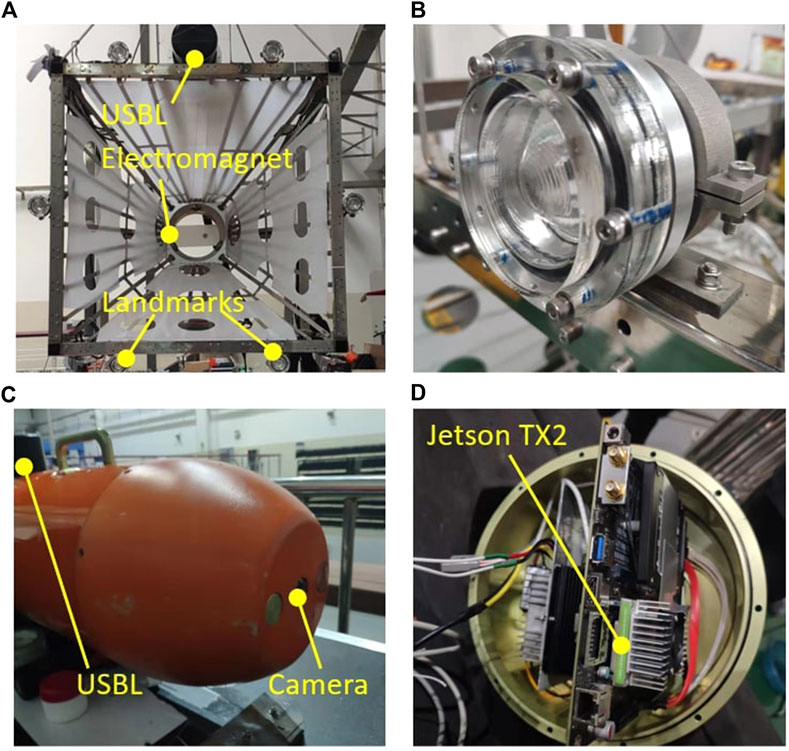
FIGURE 1. Docking systems. (A)Docking station (B) Active landmark (C) Portable AUV (D) JetsonTX2.
Our AUV is a small torpedo-shaped vehicle called Portable AUV(PAUV). The PAUV has an air weight of 80 kg, a length of 2 m, a diameter of 240 mm, and a maximum speed of 5 knots. Equipped with two tail thrusters, two culvert thrusters, and two tail rudders. PAUV mainly includes a control computer, Doppler velocity log(DVL), inertial measurement unit (IMU), GPS, acoustic sensor, optical sensor, battery units, and motors. Ultra-short baseline system (USBL) is used as acoustic guidance for long-distance navigation tasks, which can work effectively within 2 km and provide ranging and direction-finding functions. It is switched to the optical guidance method at a short range to complete the final precise docking. A NanoSeaCam monocular color camera and embedded computer NVIDIA Jetson TX2 are used for optical guidance. The camera with 20fps is installed at the bow of the PAUV, and an embedded computer is installed in the middle of the PAUV, as shown in Figures 1C,D. Jetson TX2 is an excellent embedded edge computing platform with 256 CUDA cores. The computing performance reaches 1.33 TFLOPS and only 15 W power consumption is required when running. The first view color image of the PAUV is captured by the camera and sent to Jetson TX2 for calculation. Then, the obtained guidance information is sent to the main control computer for control. Data exchange between each module is realized through LAN.
Underwater docking algorithm
In this section, we introduce the two-stage docking algorithm and landmarks tracking method. The main task of the underwater docking algorithm is to accurately identify the DS within the visual range of active landmarks and give the 3D relative position and orientation information for docking navigation. Then the AUV uses the relative attitude information to update the endpoint of the line tracking task, so as to achieve the docking mission.
Two-stage docking algorithm
The two-stage docking algorithm divides the underwater docking task into two parts: target detection and poses estimation. Target detection computes the size and position of the underwater DS obtained from the color image during the docking process, then the 2D image coordinates of each landmark are obtained through image segmentation and clustering algorithm. Pose estimation gives the relative position and orientation from the landmarks 2D coordinates by using different PnP algorithm considering the different light numbers.
Target detection
The difficulty of target detection is that the image of the underwater environment will appear blurred, noise, color shift, contrast reduction, and interference light source and occlusion in the actual environment. The above problems can be effectively solved by introducing a convolutional neural network (CNN), which has surpassed the traditional method in many target recognition tasks. A CNN called Docking Neural Network (DoNN) (Liu et al., 2019) inspired by the YOLO (Redmon et al., 2016) is used to detect DS. We first briefly introduce YOLO so that the improvement of the DoNN algorithm on docking datasets can be explained intuitively.
YOLO divides the input image into S × S grid cells, each cell predicts B bounding boxes. The bounding box is denoted by
where
The major difference between DoNN and YOLO is the loss function. DoNN redesigned the loss function used in YOLO and remove both the class loss and the confidence partial of class is compatible with docking datasets which contain only one object class. Relatively, the class score using
The experiment shows that DoNN can effectively obtain the 2D position of the DS from the pictures of the complex environment for the underwater DS image. The neural network runs on the Jetson TX2, and each image takes 0.17s. With the bounding box given by DoNN, a threshold-based segmentation is used to obtain the 2D coordinates of the landmarks. The output box of the DoNN is considered the segmented target region, which effectively shields the impact of ambient light on the landmarks division of the DS. The coordinates and numbers of lights are given by a clustering algorithm. Under the condition of observation with at least 5 landmarks, the prior knowledge is used to obtain the identification number corresponding to each landmark coordinate required by the PNP algorithm. The detection process is shown in Figure 2.
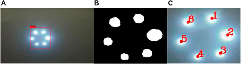
FIGURE 2. (A) Output of DoNN (B) Binary image (C) Landmarks with identification.
Pose estimation
Pose estimation in underwater docking refers to recovering 3D relative position and orientation between docking stations and AUVs from 2D images. The basic principle of the pose estimation algorithm considers that the 2D coordinates of the landmarks are the projection of the real landmarks on the visual plane, so the real 3D pose can be restored from the 2D image. In this case, the PNP algorithm estimates through several pairs of control points, one of which is in the 2D plane and the other in 3D space.
The pose referred to in this study is the position and orientation of the AUV relative to the DS, we employ Euler angles to represent rotation between the camera and the landmarks as shown in Figure 3. We denote pose vector as
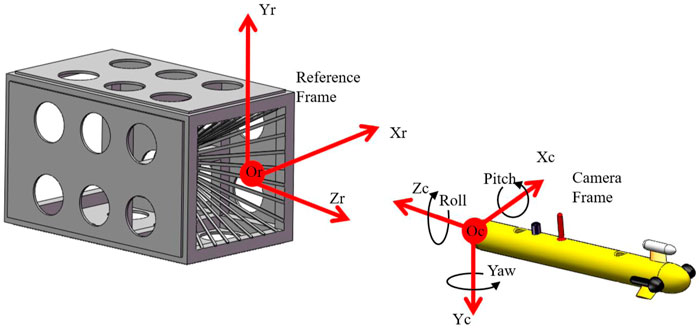
FIGURE 3. Coordinate frames used in underwater docking.
Non-iterative 3D pose estimation methods based on control points mainly include DLT (Abdel-Aziz and Karara, 1971), EPnP (Lepetit et al., 2009), R-PnP (Li, S et al., 2012). For a small number of control points, the EPnP method remains the best choice. However, as the AUV approaches or deviates greatly from the DS, it may cause incomplete observation of landmarks. Considering that the landmarks are arranged in a uniform circle, there may be only three pairs of effective control points when half or less of DS are observed, which is also common in the practical scenario, the problem will degenerate to P3P.
Although the P3P problem has four solutions, considering the continuity of video, we can still get an effective solution sequence. Intuitively, we propose to find the best solution by finding a pose vector
where
Landmark tracking algorithm
The two phases tracking algorithm remain some problem. For example, once the first stage of target detection fails, the image cannot be used for segmentation even if the image meets the estimation conditions. As shown in Figure 4, during the docking process of AUV, with the gradual reduction of the distance from the DS, it is easy to enter the blind area of the camera. Similarly, under the large initial error condition, AUV will enter the camera blind area and lose guidance too early. The larger the error in the early stage of docking, the more eager guidance information is needed (Xie et al., 2021). If we can effectively use the observation information of the landmarks in a short distance to give the estimated relative position and orientation can effectively improve the reliability of terminal guidance.
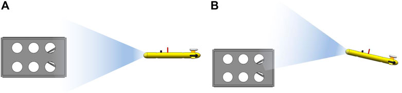
FIGURE 4. (A) Complete observation; (B) Incomplete observation.
The aforementioned problems can be effectively solved by introducing the landmarks tracking method. SORT was proposed as a classic multi-target tracking framework (Bewley et al., 2016). Referring to this algorithm, a landmarks-based tracking framwork is proposed. The proposed tracking framework combining two-stage docking and SORT is shown in Figure 5.
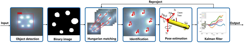
FIGURE 5. Tracking framework combing two-stage docking and SORT algorithm.
Based on the two-stage algorithm, Hungarian matching and Kalman filter in the SORT algorithm are introduced for tracking. For the tracking part, we retain the IOU loss function in SORT and delete the targets with large IOU loss. In addition, considering that the DS is a whole, instead of predicting multi landmarks, the Kalman filter is applied directly to the final detection results to estimate the pose of the next frame. The predicted result is then projected on the 2D coordinate plane so that it can be matched with the current incomplete observation to obtain the match of control points, which is required in the PnP algorithm. Considering the continuity of the docking process, we believe that there will not be much change in a continuous sequence of images, so the neural network method can be independent of the segmentation method after the DS is detected. Through this structure, the segmentation algorithm can continue to work, using the information of the previous frame in the case of detection failure. Figure 6 shows that the algorithm can still effectively match control point pairs when only three landmarks are observed.
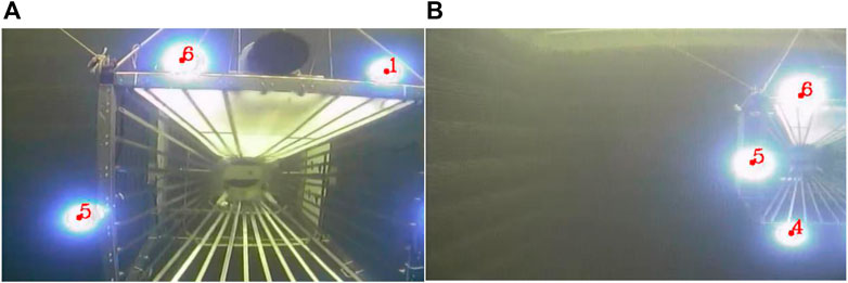
FIGURE 6. (A) Tracking results in close incomplete observation (B) Tracking result in big deviation incomplete observation.
Experimental analysis and results
In this part, we compared and verified the algorithm by only executing optical guidance in the pool environment. In the lake experiment, the acoustic guidance system was used for long-distance guidance, and the robustness of the algorithm was verified in combination with short-range optical guidance.
Water pool experiment
Our goal in the pool experiment is to verify the feasibility of close-range guidance and evaluate the performance by using only the visual guidance algorithm. The pool experiment provides the basis for the real environment experiment on the lake. We experimented with a 10 m wide, 25 m long, and 7 m deep pool, and the water quality was clear. The center of the DS is hoisted to a position 2 m underwater from the water surface. When the AUV is 20 m away from the DS radially, it performs the underwater docking task from the water surface. The forward speed is 0.5 m/s. The whole docking process is only completed by the visual method. A successful docking is shown in Figure 7. In the pool environment, five docking operations were carried out with different initial positions and angles, all the docking was successful. The trajectories of the five recovery processes are shown in Figure 8.

FIGURE 7. Docking process image in water pool.
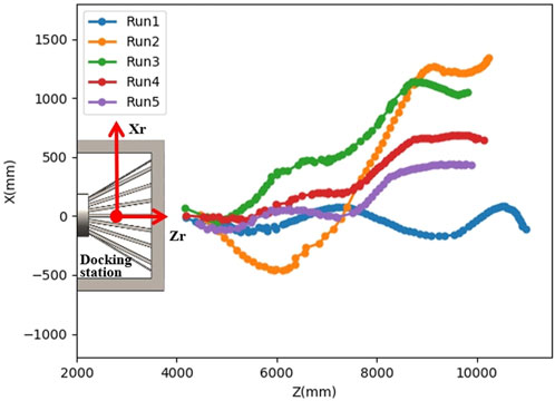
FIGURE 8. Trajectories of the five recovery processes in water-pool.
Field experiment
The purpose of the outfield test is to verify the robustness of the algorithm in the field environment based on the pool experiment and to verify the system stability of the acoustic system for correct optical terminal guidance. The field test was carried out in Fuxian Lake, China. The elevation of Fuxian Lake is 1722.5 m, the average water depth is 95.2 m, and the water quality is relatively clear. We selected a relatively flat terrain and placed the DS at the bottom of the lake in advance to ensure its stability. The center of the DS is about 15 m underwater away from the water surface. The AUV dives from the water surface at a distance of 1000 m from the DS and starts the homing and docking mission. First, rough guidance is carried out through acoustic guidance, and then switched to optical guidance when it is 15 m away from the DS.
When performing short-range optical docking, the forward speed is 0.5 m/s. We conducted 4 docking tests on the lake, including 3 successes and 1 failed docking. Figures 9, 10 show a successful and a failed docking process. Data show that the docking distance on the lake has been reduced, accompanied by more disturbances.
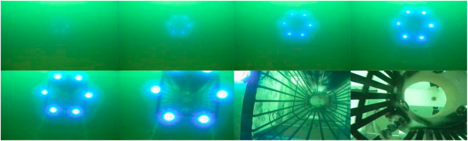
FIGURE 9. Docking process image in the lake (success).
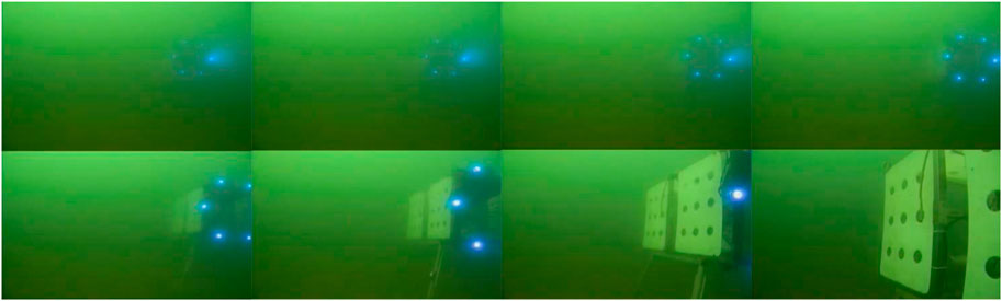
FIGURE 10. Docking process image in the lake (failed).
As shown in Figure 10, when the DS is seen, the optical module gives a correct estimation. It can be seen from the image that AUV is deflecting towards DS. However, AUV cannot enormously adjust pose within a short distance owing to inherent mobility, and it missed the DS.
It is noteworthy that in the failed run4 as shown in Figure 11, the prediction of P3P accounted for 33% of the effective output and lasted for 1.6 m in the final stage. If the position and attitude information provided by P3P is missing, AUV will lose guidance information earlier with a large deviation. It can be seen that the P3P algorithm can still provide final help at the boundary of the visual blind area, to expand the workspace of the docking algorithm.

FIGURE 11. Trajectories of the four recovery processes in the lake.
Conclusion
In this study, an underwater active landmark tracking algorithm is proposed to complete the terminal optical guidance. The beneficial characteristics of the neural network are used to effectively identify the DS in the field environment. By introducing the tracking framework, observation failure caused by short-range and large observation angles is improved, and good docking accuracy and robustness are shown in the water pool and field experiments.
Acoustic guidance is the pre-step of optical landmarks guidance in the outfield experiment. It is found that if the USBL system cannot effectively bring the vehicle into the visual range of landmarks for optical guidance, the whole docking process will fail no matter how accurate the optical guidance algorithm is. Therefore, if the effective working scopes of optical guidance can be effectively improved, it will be of great significance to the whole guidance system. In the future, further research will be carried out on how to improve the directivity and working range of optical guidance.
Data availability statement
The raw data supporting the conclusion of this article will be made available by the authors, without undue reservation.
Author contributions
KS made substantial contributions to the supervision and environmental support of the work. ZH completed the writing of the manuscript. All authors participated in the design and act of the experiment, data analysis, report development, revision, and approved the final version.
Funding
This study is supported by the State Key Laboratory of Robotics Foundation (No. 2017-Z05).
Conflict of interest
The authors declare that the research was conducted in the absence of any commercial or financial relationships that could be construed as a potential conflict of interest.
Publisher’s note
All claims expressed in this article are solely those of the authors and do not necessarily represent those of their affiliated organizations, or those of the publisher, the editors, and the reviewers. Any product that may be evaluated in this article, or claim that may be made by its manufacturer, is not guaranteed or endorsed by the publisher.
References
Adbel-Aziz, Y. I., and Karara, H. M. (1971). “Direct linear transformation from comparator coordinates into object space in close-range photogrammetry,” in ASP Symp. Proc. on Close-Range Photogrammetry, Falls Church, 1971 (American Society of Photogrammetry), 1–18.
Bewley, A., Ge, Z., Ott, L., Ramos, F., and Upcroft, B. (2016). “Simple online and realtime tracking,” in 2016 IEEE international conference on image processing (ICIP), Phoenix, AZ, USA, 25-28 September 2016 (IEEE), 3464–3468. doi:10.1109/ICIP.2016.7533003
De Leo, F. C., Ogata, B., Sastri, A. R., Heesemann, M., Mihály, S., Galbraith, M., et al. (2018). High-frequency observations from a deep-sea cabled observatory reveal seasonal overwintering of Neocalanus spp. in Barkley Canyon, NE Pacific: Insights into particulate organic carbon flux. Prog. Oceanogr. 169, 120–137. doi:10.1016/j.pocean.2018.06.001
Deeb, A., Svendsen, K., Gregson, E., Seto, M., Burchill, N., and Covill, J. (2019). “Intelligent subsea lander network to support resident AUVs for long duration under-ice ocean observations,” in OCEANS 2019 MTS/IEEE SEATTLE, Seattle, WA, USA, 27-31 October 2019 (IEEE), 1–9. doi:10.23919/OCEANS40490.2019.8962766
Deltheil, C., Didier, L., Hospital, E., and Brutzman, D. P. (2000). Simulating an optical guidance system for the recovery of an unmanned underwater vehicle. IEEE J. Ocean. Eng. 25 (4), 568–574. doi:10.1109/48.895364
Ghosh, S., Ray, R., Vadali, S. R. K., Shome, S. N., and Nandy, S. (2016). Reliable pose estimation of underwater dock using single camera: A scene invariant approach. Mach. Vis. Appl. 27 (2), 221–236. doi:10.1007/s00138-015-0736-4
Lepetit, V., Moreno-Noguer, F., and Fua, P. (2009). Epnp: An accurate o (n) solution to the pnp problem. Int. J. Comput. Vis. 81 (2), 155–166. doi:10.1007/s11263-008-0152-6
Li D. J., D. J., Chen, Y. H., Shi, J. G., and Yang, C. J. (2015). Autonomous underwater vehicle docking system for cabled ocean observatory network. Ocean. Eng. 109, 127–134. doi:10.1016/j.oceaneng.2015.08.029
Li, S., Xu, C., and Xie, M. (2012). A robust O (n) solution to the perspective-n-point problem. IEEE Trans. Pattern Anal. Mach. Intell. 34 (7), 1444–1450. doi:10.1109/tpami.2012.41
Li, Y., Jiang, Y., Cao, J., Wang, B., and Li, Y. (2015). AUV docking experiments based on vision positioning using two cameras. Ocean. Eng. 110, 163–173. doi:10.1016/j.oceaneng.2015.10.015
Lin, M., Lin, R., Yang, C., Li, D., Zhang, Z., Zhao, Y., et al. (2022). Docking to an underwater suspended charging station: Systematic design and experimental tests. Ocean. Eng. 249, 110766. doi:10.1016/j.oceaneng.2022.110766
Liu, S., Ozay, M., Okatani, T., Xu, H., Sun, K., and Lin, Y. (2018). Detection and pose estimation for short-range vision-based underwater docking. IEEE Access 7, 2720–2749. doi:10.1109/access.2018.2885537
Liu, S., Xu, H., Lin, Y., and Gao, L. (2019). Visual navigation for recovering an AUV by another AUV in shallow water. Sensors 19 (8), 1889. doi:10.3390/s19081889
Liu, S., Yu, J., Deng, S., and Wan, S. (2021). “An efficient-communication federated learning approach for vehicular edge computing in 6G communication networks. IEEE Transact. Intell. Transportat. Syst. 23 (2), 1616–1629.
Maire, F., Prasser, D., Dunbabin, M., and Dawson, M. (2009). “A vision based target detection system for docking of an autonomous underwater vehicle,” in Proceedings of the 2009 Australasian Conference on Robotics and Automation, May12-17, 2009, Kobe, Japan (Australian Robotics & Automation Association), 1–7.
Manalang, D., and Delaney, J. R. (2016). “Axial seamount-restless, wired and occupied: A conceptual overview of resident AUV operations and technologies,” in OCEANS 2016 MTS/IEEE Monterey, Monterey, CA, USA, 19-23 September 2016 (IEEE), 1–7. doi:10.1109/OCEANS.2016.7761305
Palomeras, N., Vallicrosa, G., Mallios, A., Bosch, J., Vidal, E., Hurtos, N., et al. (2018). AUV homing and docking for remote operations. Ocean. Eng. 154, 106–120. doi:10.1016/j.oceaneng.2018.01.114
Park, J. Y., Jun, B. H., Lee, P. M., and Oh, J. (2009). Experiments on vision guided docking of an autonomous underwater vehicle using one camera. Ocean. Eng. 36 (1), 48–61. doi:10.1016/j.oceaneng.2008.10.001
Redmon, J., Divvala, S., Girshick, R., and Farhadi, A. (2016). “You only look once: Unified, real-time object detection,” Proceedings of the IEEE conference on computer vision and pattern recognition. Las Vegas, NV, USA, 27-30 June 2016, 779–788. doi:10.1109/CVPR.2016.91
Sans-Muntadas, A., Kelasidi, E., Pettersen, K. Y., and Brekke, E. (2019). Learning an AUV docking maneuver with a convolutional neural network. IFAC J. Syst. Control 8, 100049. doi:10.1016/j.ifacsc.2019.100049
Seyfried, W. E., Tan, C., Wang, X., Wu, S., Evans, G. N., Coogan, L. A., et al. (2022). Time series of hydrothermal vent fluid chemistry at Main Endeavour Field, juan de Fuca Ridge: Remote sampling using the NEPTUNE cabled observatory. Deep Sea Res. Part I Oceanogr. Res. Pap. 186, 103809. doi:10.1016/j.dsr.2022.103809
Wang, T., Zhao, Q., and Yang, C. (2021). Visual navigation and docking for a planar type AUV docking and charging system. Ocean. Eng. 224, 108744. doi:10.1016/j.oceaneng.2021.108744
Xie, T., Li, Y., Jiang, Y., Pang, S., and Wu, H. (2021). Turning circle based trajectory planning method of an underactuated AUV for the mobile docking mission. Ocean. Eng. 236, 109546. doi:10.1016/j.oceaneng.2021.109546
Yazdani, A. M., Sammut, K., Yakimenko, O., and Lammas, A. (2020). A survey of underwater docking guidance systems. Robotics Aut. Syst. 124, 103382. doi:10.1016/j.robot.2019.103382
Zhou, J., Zhang, W., Wu, D., and Hao, Y. (2014). “Underwater recovery realization for an AUV using positioning-to-line strategy,” in 2014 IEEE Conference and Expo Transportation Electrification Asia-Pacific (ITEC Asia-Pacific), Beijing, 31 August 2014 - 03 (IEEE), 1–5. doi:10.1109/ITEC-AP.2014.6940744
Keywords: autonomous underwater vehicle, underwater docking, visual navigation, underwater active landmarks, marine robotics, low carbon
Citation: Sun K and Han Z (2022) Autonomous underwater vehicle docking system for energy and data transmission in cabled ocean observatory networks. Front. Energy Res. 10:960278. doi: 10.3389/fenrg.2022.960278
Received: 02 June 2022; Accepted: 18 July 2022;
Published: 24 August 2022.
Edited by:
Yushuai Li, University of Oslo, NorwayReviewed by:
Tsung-Chow Su, Florida Atlantic University, United StatesMing Li, Ocean University of China, China
Jinhai Liu, Northeastern University, China
Copyright © 2022 Sun and Han. This is an open-access article distributed under the terms of the Creative Commons Attribution License (CC BY). The use, distribution or reproduction in other forums is permitted, provided the original author(s) and the copyright owner(s) are credited and that the original publication in this journal is cited, in accordance with accepted academic practice. No use, distribution or reproduction is permitted which does not comply with these terms.
*Correspondence: Kai Sun, c3Vua0BzaWEuY24=