 Sainan Xue
 Zhuojun Ying
 Hu Ma
Hu Ma Changsheng Zhou1
- 1School of Mechanical Engineering, Nanjing University of Science and Technology, Nanjing, China
- 2Gas Turbine Establishment, Chengdu, China
The operating characteristic of two-phase rotating detonation fueled by kerosene in a hollow combustor with the isolation section is experimentally studied. When the air mass flow rate is 1.5 kg/s, the equivalence ratio is 0.98, and the total temperature of the mixture is 650 K, the stable rotating detonation wave (RDW) is obtained, which verifies the feasibility of the designed two-phase rotating detonation combustor (RDC). It is found that there is a high-frequency oblique shock induced by the upstream rotating detonation wave in the isolation section. A series of experimental tests have been carried out by changing the total temperature of incoming air , which is an important factor affecting the initiation. When the equivalent ratio of reactants is between 0.950–1.152, a stable single-wave detonation is formed. With the increase of equivalent ratio, the time of detonation wave establishment decreases, the intensity and frequency of detonation wave increases, and the temperature of engine tail flame rises. The equivalent chamber pressure Δpφ was defined, and the curve of the performance of the RDC with the equivalent ratio was obtained. The velocity of the RDW increases with the increase of equivalent ratio, and the chamber pressure has an optimal value, a higher or lower equivalent ratio will lead to the decrease of equivalent chamber pressure and the combustion chamber performance.
Introduction
The rotating detonation engine is a new propeller with multitudinous inherent advantages of being simple, self-pressurizing, and environment friendly and having compact configuration. Compared to conventional combustion chambers, it can increase power up to 10% while saving 25% in fuel consumption. Among the rotating detonation combustion chamber schemes, the one that differs from the current mainly used annular chamber is the hollow combustion chamber, which has no inner column in the chamber. With the elimination of the inner column, the hollow chamber can effectively avoids the problem of heat dissipation from the inner wall and takes no consideration of the corresponding cooling measures. The increasing number of studies in recent years (Teng et al., 2020; Wang et al., 2021a; Huang et al., 2021; Yan et al., 2021) foretells that rotating detonation engines will have enormous application prospects in the future.
Researchers from Peking University conducted a number of numerical studies (Tang et al., 2013; Yao et al., 2017; Liu et al., 2020), using a rotating detonation combustion chamber without the inner wall, to explore the injection model via an array of holes and found the fuel-based impulse in 1900s, which is approximate to that in the annular combustion chamber under the same condition. Huang et al. (2019) showed the effects of the pintle injector on the H2/air continuous rotating detonation wave (CRDW) in a hollow chamber, and analyzed the relationship between continuous rotating detonation (CRD) and tangential instability. Zhang et al. (2016) and Zhang et al. (2021) observed that rotating detonation is an implication to the high-frequency tangential instability. And instead of the annular combustion chamber, it is easier to establish an H2/air rotating detonation in the hollow combustion chamber. Lin et al. (2015) and Lin et al. (2020) experimentally validated that utilizing the pre-detonator and increasing mass flow rate play an important role in the stability of detonation propagation. The result indicated that injecting enough CH4/O2 mixture is the essential condition for sustaining a stable CRDW. Kawasaki et al. (2019a) and Kawasaki et al. (2019b) investigated the thrust and impulse of RDE using a propellant of C2H2-O2 for experiments, varying in the inner cylinder radius from 31 to 0 mm. The results confirmed the engine performance with no-inner-cylinder configuration approximate to the others. Anand et al. (2016) carried out the experimental research with an H2-air hollow RDC, and calculated that the concomitant detonation wave speeds are upward of 90% of the ideal Chapman–Jouguet (C-J) speed at rich conditions of operation. Liu et al. (2021) focused on the characteristics of the methane-air CRDW in a small chamber. The propagation velocity accounts for 99% of the theoretical C-J velocity in the chosen test.
The researchers demonstrated through the above experiments that rotating detonation can not only be established in the hollow combustion chamber, but also outperform the conventional RDE. In solving the problem about a hollow RDC without the narrow ring slot, it cannot be simply assumed to be a two-dimensional problem. It requires a highly complex three-dimensional resolution. Moreover, due to the same injection pattern with the annular chamber, a large reflux region with high pressure loss is observed at the head of a hollow RDC.
Currently, gaseous fuels were generally used in the studies of the hollow RDC. Wang et al. (2018), Peng et al. (2018), and Peng et al. (2019) obtained the single- and double-rotating detonation wave in the experiments based on hydrocarbon fuels such as methane and ethylene. Analyzing the rotating detonation propagation modes, the range of stable operating conditions is significantly smaller due to the worse detonation of methane. Nevertheless, the combined advantages of liquid fuels are higher in practice. Zheng et al. (2020) studied the instability RDW propagation characteristics of liquid kerosene in an RDC with an air-heater, and conjectured the main reason for the fluctuations of detonation wave velocity and pressure peaks along with time. Three different types of instability were observed in the experiments: temporal and spatial instability, mode transition, and re-initiation. Subsequently, Wang et al. (2021b) numerically investigated the effects of total pressures and equivalence ratios on the operation characteristics of RDE. Increasing the width of RDC was submitted by Wang et al. (2021c), which is a more reliable choice to successfully initiate the stable rotating detonation waves.
In this article, the operating characteristic of the two-phase rotating detonation fueled by kerosene in a hollow combustor is experimentally studied. Through analyzing the test results, the flow field of the isolation section and combustion chamber is distinctly obtained.
Experimental System and Methodology
Experimental System
In order to investigate the kerosene-air hollow RDC operating under a high total enthalpy flow, a direct-connected RDE is designed for the experiments. As shown in Figure 1, the system consists of seven main components, including compressed air supply system, air-heater, fuel supply system, ignition system, RDE with a solation section, control system, and acquisition system.
1 Compressed air supply system

FIGURE 1. Experimental system diagram.
The air is stored in the large capacity high-pressure tank through the compressor, and flows through the pipeline into the chamber before entering the air-heater through gas filter, reduction valve, vortex flow meter, electromagnetic valve, and ball valve in sequence. According to this line, the air mass flow rate is ensured to be stabilized at 1.5–2.5 kg/s for experimental requirements.
2 Air-heater
To create the condition of high-temperature and high-pressure incoming flow, the cold air in the main circuit needs to be heated. Controlling the total temperature of the incoming flow is achieved by regulating the mass flow of hydrogen. To replenish the amount of oxygen consumed by the hydrogen fuel combustion through the oxygenating equipment, the oxygen content of the hot air is 23%.
3 Fuel delivery system
The RDE is fueled by liquid aviation kerosene (RP-3), which is stored in a high-pressure tank. Kerosene is squeezed into an injection device by nitrogen, which flows through some valves in an extrusion process. To prevent blocking the electromagnetic valve and injector by kerosene impurities, gauze filter and filter element are installed at the front of the unit. This is necessary to provide the stability and reliability of fuel delivery for RDE.
4 Ignition system
A high-energy pre-detonator is applied to ignite the RDE, and its diameter is 20 mm. Two Laval-nozzles are respectively set in the delivery system. Hydrogen and oxygen are used as reactions in a pre-detonator, injected orthogonality in a non-premixed manner, which mix at the head of the pre-detonator. The detonable mixture is ignited by an automotive spark plug, and its ignition energy is 50 mJ, which is developed to establish a rotating detonation wave through the deflagration-to-detonation transition (DDT) process.
5 Experimental RDE
RDE includes an isolation section and a rotating detonation combustion chamber, as shown in Figure 2. Perforating the outer wall of isolation and the chamber, the pressure taps are used to monitor the high-frequency and steady-state pressure signals in operation.
6 Control system
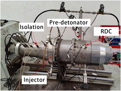
FIGURE 2. Photograph of the RDC test system.
Control system is composed of a computer, a sequence control module (8 channels), six electromagnetic valves, two sparks, and control lines as shown in the red line in Figure 1. To achieve the fuel supply and ignition timing accurately, the system needs the effective control of valves and sparks.
7 Acquisition system
Based on the NI-SRC3 synchronization technology and a 16-bit ADC resolution, an NI high-frequency data acquisition device (DAQ) is used to capture instantaneous multichannel pressure signals. The device is sampled at an acquisition frequency of 2 MS/s. The inlet of the RDC thermocouple and static pressure transducer are set to measure the total temperature and static pressure. The pressure of isolation and chamber are acquired by PCB sensors (PCB113B24), which are installed flush with the inner walls. The frequency of PCB sensors is 500 kHz, and the response time is less than 1 μs and the measurement precision is 1%FS. In addition, the steady pressure of reactant plenums and isolation have been considered. The data of air and fuel mass flow, pressure, and temperature, are collected by vortex flowmeters, are shown on the real-time detective monitor.
Furthermore, in this article a short-term test was carried out, the operation time of RDE is 1–2 s. After a single cycle, the room-temperature air flows into the RDE for 3 s to protect the sensor from damage caused by the sustaining impact of the sensor due to high-temperature and high-pressure detonation products and heat conduction from the high-temperature inner wall.
Experimental Methodology
To develop a more profound investigation, isolation, injector, and walls of chamber are designed to be removable and replaceable based on the modular design. In this experiment, a hollow rotating detonation combustor with an isolation and a unique internal injection is selected as an object of the study. The outer diameter and length of the detonation combustor are 200 and 212 mm, and a convergent nozzle is taken. It is 804 mm from the inlet of the isolation to the outlet of the nozzle.
The location of the sensors at the isolation is shown in Figure 3, which are installed on the outside wall of the isolation to measure the pressure trend of the leading shock wave and analyze the internal structure of the flow field. Three PCB sensors are, respectively, installed at the locations of a, b, and c in the isolation to infer the ending location of the normal shock wave. As the air flow is slow at the inlet of the air, a steady state pressure sensor is used to acquire the total pressure of the inlet (Pi). Similarly, sensors are installed at 94 mm from the inlet of RDC and the throat of the nozzle to measure the steady state pressure of RDC (Pr) and the total pressure of the outlet (Po). The position of the piezoresistive sensors PCB1 and PCB2 are, respectively, corresponding to d and e as shown in Figure 3, and these two PCB provide the data of pressure to analyze the induced shock wave from the chamber to isolation. The holes of injection are marked by blue circles, which are located at distance Lf, as shown in Figure 3. Two high-frequency sensors are placed in the same section, with an axial interval of 14 mm to the inlet of RDC, but the circumferential interval between P1 and P2 is clockwise 90° to judge the rotating direction of RDW. Sensor P3 and P4 are located axially at 60 and 186 mm from the location of P1.
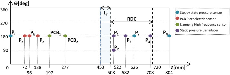
FIGURE 3. Locations of the sensors.
In this series of experiments, all operations are performed sequentially, as shown in Figure 4. Firstly, sensors are triggered so that the data acquisition system starts running and recording the high-frequency pressure oscillation in the RDC. Then, the room-temperature air is injected for one second, and the flow field is beginning to stabilize. Hydrogen and oxygen are injected into the air-heater, simultaneously the spark of heater ignites. The time set of ignition duration is 1 s for dependability. After kerosene is ejected from injection holes, which is broken into liquid film, and then turn into droplets by the shear of high-speed air flow. The droplet of Kerosene is rapidly evaporated under the action of high-temperature air, and is mixed with the air. The fresh reaction mixture is filled into the combustion chamber. Following the pre-detonator begins to fill hydrogen and oxygen and ignites by a spark plug. In the chamber, the air-kerosene mixture is lit through the DDT process establishing the rotating detonation wave . All supplies are closed successively in the end.
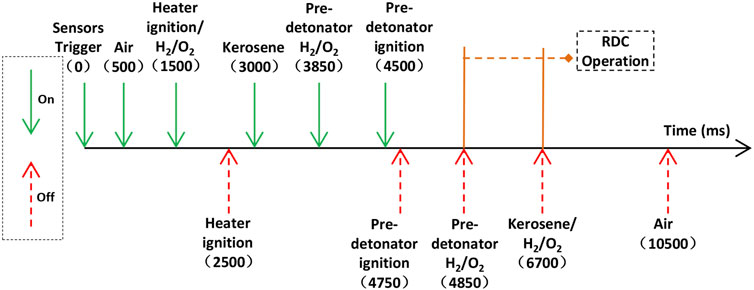
FIGURE 4. Time sequence of the experimental test.
Results and Discussion
RDC Operation Process Analysis
1 Feasibility of internal injection mode
The experimental test is carried out with a hollow RDC, in which the area of inlet throat is 8725 mm2. The air mass flow rate is 1.5 kg/s, and the equivalence ratio is 0.98. When the total temperature of the incoming flow is stable at 650 K, Figure 5A shows the signal curves of pressure. Before the heater ignites, the air is injected at the earliest, and conduced that the inlet pressure increases gradually. After ignition, the inlet pressure peaks abruptly, and then declines fleetly to 0.33 MPaT the value of the pressure is stable until the pre-detonator sparks. When the RDE starts to operate, the propagation of the detonation wave is affected by the isolation section, and the downtrend of the inlet pressure could be directly related to this. The heater and kerosene supply system are shut off, while the air supply system keeps working, so the pressure recovers to the level before the heater ignites.
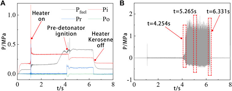
FIGURE 5. Results of operating at
Figure 5B shows a visualized curve of the original pressure signal of P1 in the combustion chamber after a high-pass filtering. The complete combustion process demonstrated how the stable rotating detonation wave is formed. When t = 4.100 s, pre-detonator ignites, and the oscillation of combustion process is shown in Figure 6. After ignition, the chamber pressure increases and remains at 0.12 MPa. Kerosene is sprayed from the injection hole, which does not evaporate completely in time. Kerosene and air are heterogeneously mixed to reduce the combustion efficiency. Therefore, kerosene and air are difficult to initiate, the detonation wave cannot be immediately established after ignition, the initial combustion mode in RDC is a deflagration combustion. Finishing the DDT process at t = 4.254 s, the rotating detonation wave begins to stably propagate.
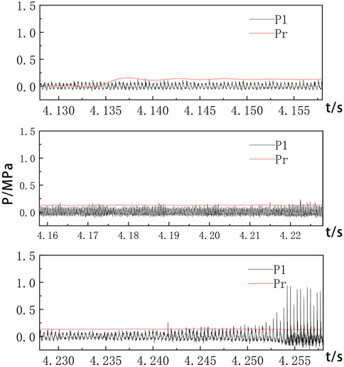
FIGURE 6. Local segmentation of the pressure signals in the initiation.
To get a visualized view, the signal data are magnified nearby t = 5.265 s, as shown in Figure 7A. The propagation period of the detonation wave is 367 µs. Figure 7B shows the results obtained by the fast Fourier transform (FFT) of the high-frequency dynamic pressure signal measured by P1. The dominant frequency of RDC is 2721 Hz, and the corresponding average velocity is 1710 m/s.
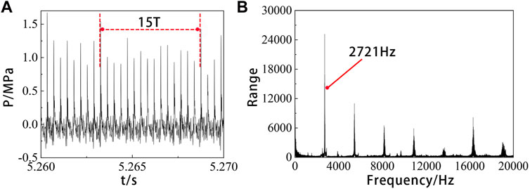
FIGURE 7. Pressure signals of P1 by operating at
As shown in Figure 8, when the fuel electromagnetic valve is closed at 6.331 s. The fuel injection pressure and mass flow gradually decline, but the air injection pressure and mass flow remain invariable, accordingly the equivalence ratio of the combustor gradually decreases, and the RDE enters the quenching stage. The propagation frequency of the rotating detonation wave presents a downward trend with time, and finally flameouts completely at 6.353 s.
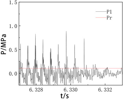
FIGURE 8. Local segmentation of the pressure signals in the quenching stage.
The above analysis elucidates that the internal injection method adopted in this article is feasible, and the self-sustained rotating detonation wave can be obtained.
2 Flow characteristic of isolation
The dynamic pressure signals in the isolation captured by PCB1 and PCB2 sensors in the test are shown in Figure 9A. The pressure peaks of detonation wave at the position of PCB2 closer to the chamber are significantly higher, and the pressure signal of PCB1 fluctuates slightly. By magnifying the signal data in the red dotted box, the complex shock waves in the isolated section are observed. The curve of PCB2 shows obvious characteristics of multi-wave peaks, and the pressure changes in the range of ± 1 MPa. Figure 9B indicates a single period of three-wave peaks, namely T1 = 362 µs, T2 = 364 µs, and T3 = 368 µs, which are approximate to the average period of the combustion chamber.
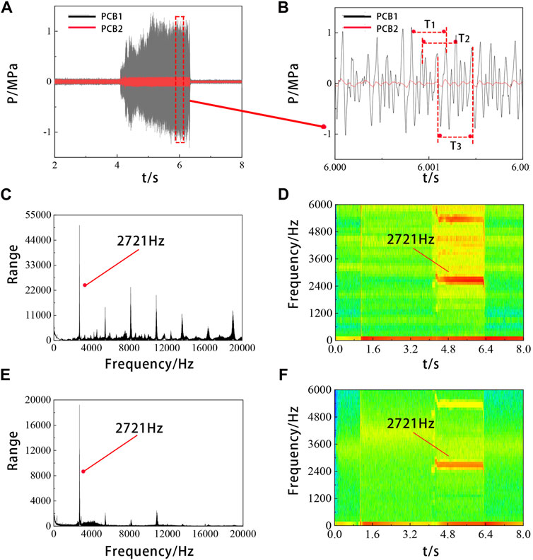
FIGURE 9. Results of operating at
Figures 9C–F respectively show the fast Fourier transform (FFT) and the short-time Fourier transform (STFT) results of the PCB1 and PCB2 pressure signals. A recognizable line appears at f = 2721 Hz, which indicates that a stable convergence value is obtained for operating frequency. The corresponding average velocity is 1708.8 m/s, which is consistent with the dominant frequency of the combustion chamber.
It is inferred from the above phenomenon that there is high-frequency rotating oblique shock waves induced by the detonation wave upstream in the isolation. The propagation of shock waves is sophisticated, two of them are inferred to be the forward spiral shock waves generated in the RDC. Influenced by the internal injection structure, the shock waves are divided into two waves with different velocities, which move upstream in the isolation section. The remaining shock waves are deduced as reflected waves when passing through the throat of isolation.
Influence on Rotating Detonation Combustion Characteristic
1 The factor of air total temperature
The parameters based on the previous experiments are unaltered except the total temperature of incoming air. The total temperature of the experimental control group are 562 K and 480 K.
When the total temperature is 562 K, the signal transformation of P1 by FFT and STFT is conducted, as shown in Figure 10. The dominant frequency of a single wave is 2778 Hz, slightly higher than 2710 Hz at 650 K, which is consistent with the theoretical law that the propagation velocity of detonation wave decreases with the increase of initial temperature.
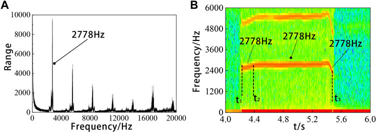
FIGURE 10. Results of operating at
The detonation time of the combustion chamber t1 = 4.22 s, correspondingly the frequency is 2563 Hz. After successful initiation, the frequency of detonation wave gradually rises until reaching a stable value of 2778 Hz at 4.41 s (t2). The process takes 0.19 s. After the heater and fuel valve are turned off, the frequency rapidly drops to 2319 Hz at t3. The actual operating time of RDC is 1.26 s (t3-t1) until the engine completely extinguishes. The engine operates in a single-wave mode all the time. In these experiments, the dominant frequency increased slightly, but not significantly.
The combustion chamber works in a stable single-wave mode throughout the whole process. Although the total temperature of the air inlet decreases by nearly 100 K compared with 650 K, its dominant frequency increases slightly, and the change of the total temperature has no obvious effects on the wave velocity of the detonation wave. It is illustrated that the effect of total temperature on the velocity of detonation wave is not obvious.
When the total temperature of incoming flow descends to 480 K, initiation fails and rotating detonation wave is not established, as shown in Figure 11. By processing the data collected by P1, the dominant frequency of the combustor is only 249 Hz, and there is no obvious frequency red line in the STFT conversion. Hence, the combustor is in a low-frequency unstable oscillation combustion mode.
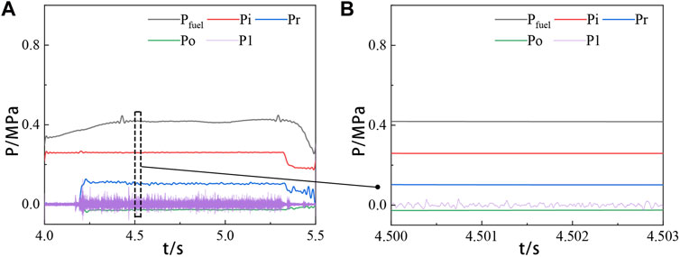
FIGURE 11. Results of operating at
The conclusion is that the variation of total temperature will affect whether the rotating detonation wave is formed. The lower limit of the air total temperature at inlet for the successful initiation in this article is between 480 and 562 K. Kerosene evaporation slows down when the inlet temperature is too low. Because of the two-phase combustion, the combustion is in an unstable low-frequency oscillation combustion state. Rotating detonation wave is not obtained.
2 The factor of equivalence ratio
The supply of kerosene is controlled by adjusting the injection pressure, and the mass flow rate of kerosene is calibrated as
When the equivalent ratio φ, respectively, are 0.914 and 0.950, a continuous rotating detonation wave is not formed. When φ = 0.950, there is a deflagration flame at the initial stage, but the flame is quenched quickly. It is concluded that the mixing efficiency is reduced. The differential pressure influences on the kerosene mass flow, which is caused by the internal injection configuration, and the effective depth penetration have shrunk when the mixture is combusted. The pressure curves in Figure 12 describe that the peak of the pressure signal measured by P1 is relatively low, in the chamber the stable rotating detonation is not found. In the high-speed image on the right, a narrow blue tail flame at the outlet of the nozzle can be seen. When the equivalent ratio is increased to 0.987, 1.086, and 1.152, respectively, the stable detonation waves are formed in the rotating detonation chamber, and it is presented a single-wave mode.
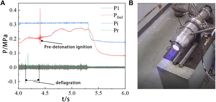
FIGURE 12. Results of operating at
The curves of the steady state pressure of RDC (Pr) and the total pressure of the outlet (Po) under three working conditions are shown in Figures 13A–C. After ignition, the stable pressure in the combustion chamber amplifies due to the combustion products of high temperature and high pressure. When the rotating detonation wave is formed, the fuel injection holes are partially blocked due to the partial high pressure of RDW, and the steady state pressure in the RDC decreases to a certain extent until it flameout.
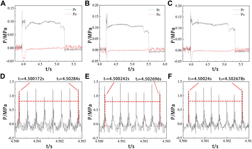
FIGURE 13. Results of operating at
When the equivalent ratio is 0.987, the establishment process of detonation wave is the longest. When the equivalent ratio is 1.152, the stable pressure amplitude is the largest in the state of detonation. It illustrates that the equivalent ratio is an important factor affecting the establishment and intensity of detonation wave in the kerosene two-phase rotating detonation combustor without the inner column. When the equivalent ratio decreases, the time taken to establish the detonation wave increases, whereas when the equivalent ratio increases, the intensity of detonation wave decreases.
Figures 13D–F show the signal data taken from the stable working stage under three working conditions, respectively. The intervals between two detonation waves are 381 µs, 351, and 348 µs. The corresponding instantaneous velocities of rotating detonation waves are 1,648.3 m/s, 1791.4 m/s, and 1803.1 m/s.
As shown in Figure 14, Figure 15, and Figure 16, after the FFT transformation of the signal P1, the propagation frequency are 2658, 2847, and 2895 Hz, respectively, which are close to the instantaneous stabilized pressure frequency of the combustion chamber. When the equivalent ratio increases, the instantaneous velocity and average velocity of the combustion chamber rises correspondingly.
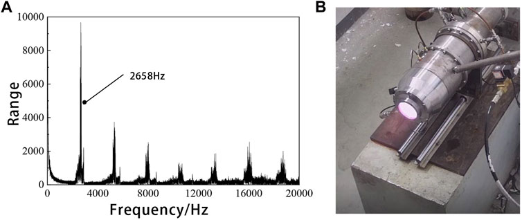
FIGURE 14. Results of operating at
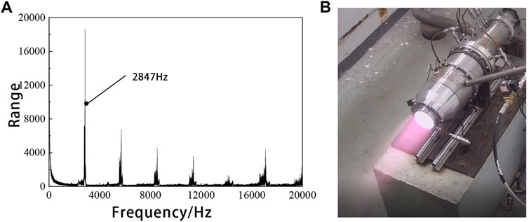
FIGURE 15. Results of operating at
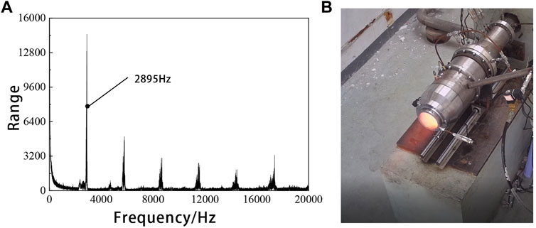
FIGURE 16. Results of operating at
The color of the flame is generally related to the temperature of the flame and the material of the fuel. In this article, only kerosene-air combustion is discussed, so the color of the flame represents the change in temperature. When the equivalent ratio is between 0.987 and 1.152, the RDC is a stable single-wave detonation, and the detonation wave frequency increases with the increase of the equivalent ratio. When the equivalent ratio is 1.086, there is a bright white tail flame at the outlet of the nozzle. And when the equivalent ratio is higher, the color of flame turns orange red. It is common sense that the higher the temperature and the darker the color. Therefore, with the increase of the equivalent ratio, the temperature of the engine exhaust gas is higher.
To evaluate the change of combustor performance with the equivalent ratio, the velocity of RDW is calculated based on the propagation frequency obtained by the aFFT, and the results are shown in Figure 17. Generally, a higher combustor pressure corresponds to a better engine propulsive performance, and the condition of the outlet pressure of the nozzle is constant. In experiments when the equivalent ratio is between 0.987–1.152, we found a rule that the pressure at the throat is close to the atmospheric pressure, and at the outlet of the nozzle, the detonation wave is a complete expansion. Hence, the equivalent chamber pressure (Δpφ) is defined as the chamber pressure difference per kilogram of kerosene that can be produced by combustion. Also, it can be obtained by
where Pr is the stable state pressure of the RDC when operating, Po is the outlet pressure, and
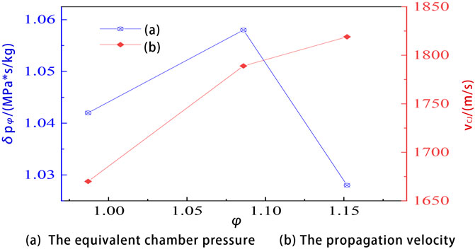
FIGURE 17. Performance of the RDC with the equivalent ratio. (A) The equivalent chamber pressure; (B) The propagation velocity.
Equivalent chamber pressure reflects the propulsion performance of the engine to a certain extent. In this articler, the relation curve of the performance of the RDC with the change of equivalent ratio was obtained as shown in Figure 17. When the equivalent ratio is near 1, the detonation wave velocity increases with the increase of the equivalent ratio. When the equivalent ratio exceeds 1.086, the propagation velocity increases slowly, and the maximum propagation velocity reaches 1819 m/s, exceeding 90% of the C-J velocity. The equivalent chamber pressure increases first and then decreases with the increase of the equivalent ratio, and comes to the lowest when φ = 1.152. The equivalent ratio has a great influence on the performance of the RDC. An optimal equivalent chamber pressure exists when the equivalent ratio is between 0.987 and 1.152. A higher or lower equivalent ratio will lead to lower equivalent chamber pressure, which will affect the combustion efficiency and reduce the combustion chamber performance.
Conclusion
In this article, a hollow RDC with the isolation section is investigated by varying the air total temperature of the incoming and the equivalent ratio. The room-temperature air and kerosene are selected as the oxidizer and fuel, respectively. The main conclusions are drawn as follows:
1 When the air mass flow rate is 1.5 kg/s, the equivalent ratio is 0.98 and the total temperature of the mixture is 650 K, the RDW undergone the DDT process is established by the pre-detonator, and the average velocity of RDW is 1710 m/s. The result of the test demonstrates that the scheme of two-phase hollow RDC is feasible.
2 It is found that there is a high-frequency oblique shock induced by the upstream rotating detonation wave in the isolation section.
3 The total temperature of incoming air is an important factor affecting the initiation. When the total temperature of air is 562 K in the experimental test, the rotating detonation combustion operates in a stable single-wave mode throughout the whole process. The dominant propagation frequency is slightly faster than that at 650 K. In a series of tests, which have been carried out, the lower limit of the air total temperature for the successful initiation is between 480 and 562 K.
4 The effects of the equivalent ratio on the performance of the RDC is significant. The supply of kerosene is controlled by adjusting the injection pressure. After recalibrating the mass flow rate of kerosene, the experimental tests are conducted. When the equivalent ratio of reactants is 0.914 or 0.950, the rotating detonation waves are not established smoothly. When φ = 0.950, there is a deflagration flame in the initial stage, but the flame is quenched quickly. When the equivalent ratio is increased to 0.987, 1.086, and 1.152, respectively, a stable single detonation waves are formed in the RDC. When the equivalent ratio increases, the time taken to establish the detonation wave decreases, the intensity and the frequency of detonation wave increases, and the temperature of engine exhaust gas is higher.
5 The equivalent chamber pressure Δpφ was defined, and the curve of the performance of the RDC with the equivalent ratio was obtained. The velocity of the RDW increases with the increase of equivalent ratio, and the equivalent chamber pressure has an optimal value, a higher or lower equivalent ratio will lead to the decrease of equivalent chamber pressure and the combustion chamber performance.
Data Availability Statement
The raw data supporting the conclusion of this article will be made available by the authors, without undue reservation.
Author Contributions
SX: experimental design, data analysis, and writing; ZY: building experimental systems and experimental data processing; HM: providing overall ideas and data analysis; and CZ: guiding the experimental operation.
Funding
This work was supported by the National Natural Science Foundation of China (12072163, 5210060296, and 11802134) and the National Defense Science and Technology Key Laboratory Foundation (HTKJ2020KL011004-1).
Conflict of Interest
The authors declare that the research was conducted in the absence of any commercial or financial relationships that could be construed as a potential conflict of interest.
Publisher’s Note
All claims expressed in this article are solely those of the authors and do not necessarily represent those of their affiliated organizations, or those of the publisher, the editors, and the reviewers. Any product that may be evaluated in this article, or claim that may be made by its manufacturer, is not guaranteed or endorsed by the publisher.
Acknowledgments
Throughout the writing of this dissertation, the authors have received a great deal of support and assistance. They would particularly like to thank their teammates and professor for their wonderful collaboration and wise counseling. In addition, they would like to thank their parents and Yuge Zhang for their patient support and sympathetic ear.
Abbreviations
C-J, Chapman-Jouguet; CRD, continuous rotating detonation; CRDW, continuous rotating detonation wave; DAQ, data acquisition device; DDT, deflagration-to-detonation transition; FFT, fast Fourier transform; RDW, rotating detonation wave; RDC, rotating detonationcombustor; STFT, short-time Fourier transform.
References
Anand, V., St. George, A. C., Gutmark, E. J., and Gutmark, E. (2016). “Hollow Rotating Detonation Combustor,” in 54th AIAA Aerospace Sciences Meeting, 4-8 January 2016 (San Diego, California, USA: AIAA). doi:10.2514/6.2016-0124
Huang, S., Li, Y., Zhou, J., Liu, S., and Peng, H. (2019). Effects of the Pintle Injector on H2/air Continuous Rotating Detonation Wave in a Hollow Chamber. Int. J. Hydrogen Energy 44, 14044–14054. doi:10.1016/j.ijhydene.2019.04.011
Huang, Y., Xia, H., Chen, X., Luan, Z., and You, Y. (2021). Shock Dynamics and Expansion Characteristics of an Aerospike Nozzle and its Interaction with the Rotating Detonation Combustor. Aerosp. Sci. Technol. 117, 106969. doi:10.1016/j.ast.2021.106969
Kawasaki, A., Inakawa, T., Kasahara, J., Goto, K., Matsuoka, K., Matsuo, A., et al. (2019). Critical Condition of Inner Cylinder Radius for Sustaining Rotating Detonation Waves in Rotating Detonation Engine Thruster. Proc. Combust. Inst. 37, 3461–3469. doi:10.1016/j.proci.2018.07.070
Kawasaki, A., Yokoo, R., Goto, K., Kim, J.-H., Matsuoka, K., Kasahara, J., et al. (2019). “An Experimental Study of In-Space Rotating Detonation Rocket Engine with Cylindrical Configuration,” in AIAA Propulsion and Energy 2019 Forum, 19-22 August 2019 (Indianapolis, IN: AIAA), 19–22. doi:10.2514/6.2019-4298
Lin, W., Tong, Y., Lin, Z., Nie, W., and Su, L. (2020). Propagation Mode Analysis on H2-Air Rotating Detonation Waves in a Hollow Combustor. AIAA J. 58, 5052–5062. doi:10.2514/1.J058254
Lin, W., Zhou, J., Liu, S., and Lin, Z. (2015). An Experimental Study on CH4/O2 Continuously Rotating Detonation Wave in a Hollow Combustion Chamber. Exp. Therm. Fluid Sci. 62, 122–130. doi:10.1016/j.expthermflusci.2014.11.017
Liu, S.-J., Huang, S.-Y., Peng, H.-Y., and Yuan, X.-Q. (2021). Characteristics of Methane-Air Continuous Rotating Detonation Wave in Hollow Chambers with Different Diameters. Acta Astronaut. 183, 1–10. doi:10.1016/j.actaastro.2021.02.035
Liu, X.-Y., Chen, Y.-L., Xia, Z.-J., and Wang, J.-P. (2020). Numerical Study of the Reverse-Rotating Waves in Rotating Detonation Engine with a Hollow Combustor. Acta Astronaut. 170, 421–430. doi:10.1016/j.actaastro.2020.02.008
Peng, H. Y., Liu, W. D., Liu, S. J., Zhang, H. L., and Zhou, W. Y. (2019). Realization of Methane-Air Continuous Rotating Detonation Wave. Acta Astronaut. 164, 1–8. doi:10.1016/j.actaastro.2019.07.001
Peng, H., Liu, W., Liu, S., and Zhang, H. (2018). Experimental Investigations on Ethylene-Air Continuous Rotating Detonation Wave in the Hollow Chamber with Laval Nozzle. Acta Astronaut. 151, 137–145. doi:10.1016/j.actaastro.2018.06.025
Tang, X., Wang, J., and Shao, Y. (2013). 3-D Simulation of Rotating Detonation Wave in Combustion Chambers without Inner Wall. J. Aerosp. Power 28, 792–799. doi:10.13224/j.cnki.jasp.2013.04.013
Teng, H., Zhou, L., Yang, P., and Jiang, Z. (2020). Numerical Investigation of Wavelet Features in Rotating Detonations with a Two-step Induction-Reaction Model. Int. J. Hydrogen Energy 45 (7), 4991–5001. doi:10.1016/j.ijhydene.2019.12.063
Wang, B., Xie, Q., Wen, H., Teng, H. H., Zhang, Y. N., Zhou, L., et al. (2021). Research Progress of Detonation Engines. Joutnal Propuls. Technol. 42 (4), 721–737. doi:10.13675/j.cnki.tjjs.210109
Wang, F., Weng, C. S., Wu, Y. W., Bai, Q. D., Zheng, Q., and Xu, H. (2021). Effects of Total Pressures and Equivalence Ratios on Kerosene/air Rotating Detonation Engines Using a Paralleling CE/SE Method. Def. Technol. 17 (6), 1805–1816. doi:10.3969/j.issn.2214-9147.2021.06.00110.1016/j.dt.2020.09.015
Wang, Y., Le, J., Wang, C., and Zheng, Y. (2018). A Non-premixed Rotating Detonation Engine Using Ethylene and Air. Appl. Therm. Eng. 137, 749–757. doi:10.1016/j.applthermaleng.2018.04.015
Wang, Z., Yan, Y., Wang, K., Zhu, Y., Hao, Z. M., Fan, W., et al. (2021). Effects of Combustor Width on Propagation Modes of Rotating Detonation Waves Utilizing Liquid Kerosene. J. Propuls. Technol. 42 (4), 842–850. doi:10.13675/j.cnki.tjjs.200256
Yan, C., Teng, H., and Ng, H. D. (2021). Effects of Slot Injection on Detonation Wavelet Characteristics in a Rotating Detonation Engine. Acta Astronaut. 182, 274–285. doi:10.1016/j.actaastro.2021.02.010
Yao, S., Han, X., Liu, Y., and Wang, J. (2017). Numerical Study of Rotating Detonation Engine with an Array of Injection Holes. Shock Waves 27 (3), 467–476. doi:10.1007/s00193-016-0692-6
Zhang, H., Liu, W., and Liu, S. (2016). Effects of Inner Cylinder Length on H2/air Rotating Detonation. Int. J. Hydrogen Energy 41, 13281–13293. doi:10.1016/j.ijhydene.2016.06.083
Zhang, H., Liu, W., and Liu, S. (2021). Research on H2/Air Rotating Detonation in the Hollow Chamber with Double Injection. Int. J. Hydrogen Energy 46, 23067–23074. doi:10.1016/j.ijhydene.2021.04.102
Keywords: rotating detonation wave, hollow combustor, kerosene, two-phase, equivalent ratio
Citation: Xue S, Ying Z, Ma H and Zhou C (2022) Experimental Investigation on Two-Phase Rotating Detonation Fueled by Kerosene in a Hollow Directed Combustor. Front. Energy Res. 10:951177. doi: 10.3389/fenrg.2022.951177
Received: 23 May 2022; Accepted: 13 June 2022;
Published: 14 July 2022.
Edited by:
Lei Luo, Harbin Institute of Technology, ChinaReviewed by:
Shengbing Zhou, Chongqing University, ChinaYue Huang, Xiamen University, China
Honghui Teng, Beijing Institute of Technology, China
Copyright © 2022 Xue, Ying, Ma and Zhou. This is an open-access article distributed under the terms of the Creative Commons Attribution License (CC BY). The use, distribution or reproduction in other forums is permitted, provided the original author(s) and the copyright owner(s) are credited and that the original publication in this journal is cited, in accordance with accepted academic practice. No use, distribution or reproduction is permitted which does not comply with these terms.
*Correspondence: Hu Ma, bWFodW9rb2tAMTYzLmNvbQ==