- 1School of Electrical Engineering, Southeast University, Nanjing, China
- 2Nanjing Power Supply Company State Grid Jiangsu Electric Power CO., LTD, Nanjing, China
Reusing traction electric machine windings in electric vehicles as an integrated filtering inductor is a promising solution to reduce the size of the vehicle to grid (V2G) charging/discharging system. Obviously, the integrated inductors need to meet the requirements of traction and charging/discharging, which brings challenge for the design of traction machines. As one of the most popular traction electric machine types, the high-speed induction machine usually has large electrical time constant and consequently unacceptably long transient time in the design stage when finite element analysis is adopted. In this article, a method is proposed to quickly and accurately calculate the steady state performance of the induction machine by time-stepping transient magnetic finite element analysis. First, the stator current magnitude is ramped up from zero to full magnitude gradually to control the DC component in rotor flux and torque. Second, a multistep equivalent resistance method is adopted to decrease rotor time constant and suppress slot-tooth harmonic transient response. The proposed method can predict the FEA computation load before running the calculation, and it does not rely on the machine parameter and feedback signal. Its performance is tested by an example induction machine. The result shows that the proposed method can reduce the finite element calculation time of a high-speed operating point by 99%.
1 Introduction
As an emerging type of distributed energy resources (DERs), the electric vehicle is increasingly connected to the power grid in the two-way charging and discharging manner (Haghbin et al., 2013; Khaligh and D’Antonio, 2019). To suppress the harmonics brought by the grid-connected inverters, filter inductors are usually required to be installed between the inverter and the power grid. Integrated filter inductors reused traction electric machine windings instead of adding an extra set of inductors for the purpose of reducing the charging system size (Xiao et al., 2019; Metwly et al., 2020; Wang et al., 2020). It is well known that the vehicle traction application requires the machine to have high efficiency and small size, while the V2G application focuses more on the power quality such as harmonic components. Hence, it is necessary to make sure the machine can satisfy the requirements of both applications.
Induction machines (IMs) are commonly used in electric and hybrid vehicle traction (Zhu and Howe, 2007; El-Refaie, 2013). To improve machine efficiency, the IMs need to operate at high speed, which results in a large rotor electrical time constant
To reduce the calculation time, many researchers have proposed different ideas to calculate the initial steady state performance in a relatively short time. The locked-rotor method sets the rotor speed to be zero and increases rotor resistance by a factor of
The current excitation is transitioned to a voltage excitation in Di et al. (2019), which reduces the transient time by as much as 66%. However, the research does not provide theoretical analysis on the optimal transition moment. The time-harmonic (TH) FEA and larger time step methods are also studied (Fu et al., 2012; Rainer et al., 2012). However, these methods cannot guarantee the accuracy of the result. Hence, they face the same transition transient response issue when switched back to the accurate time-stepping FEA model.
This article proposes a two-step IM performance calculation method to accelerate the machine design process. The first step is to control the DC component in rotor flux and torque by gradually ramping up stator current magnitude. The second step is to reduce the rotor time constant by slowing down rotor speed and increasing rotor resistance simultaneously.
The content of this article is organized as follows: in Section 2, the transient dynamic of the IM under current source excitation is discussed. The performance of several existing methods is analyzed. Section 3 presents and discusses the proposed method. Then, the performance of the proposed method is tested by an example induction machine in Section 4. Section 5 concludes the article.
2 Performance of Existing Methods
2.1 Steady State Model in the DQ Reference Frame
The rotor flux, current, and torque of an IM in synchronous d − q reference frame can be expressed by (1–5). Since current excitation is supplied to the stator winding, the transient response is mainly on the rotor flux and current. Hence, the stator voltage and flux equations are not included.
The reference d-axis is selected such that ids and iqs satisfy (6) and (7), respectively, in the steady state.
Regardless of the transient waveform of the stator current, as long as the steady state inputs Is and ωslip are known, solving (1–4) and setting all differential terms to be zero can obtain the steady state rotor flux value as expressed by 8 and 9.
When the current source is imposed on stator winding, the transient response of the IM is mainly referring to oscillation of the rotor current, flux, and torque. (10) and (11) can be derived from (1–4). Note that rotor speed ωr is an input value in the FEA calculation, so slip frequency ωslip = sωe = ωe − ωr can be designated.
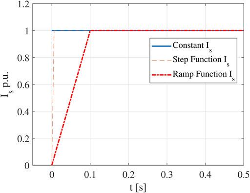
Three existing methods, including constant Is method, step function Is method, and ramp function Is method, will be discussed in the following subsections (Cai, 2020). They are different because of the different input stator current waveforms as shown in Figure 1.
2.2 Existing Method 1—Constant Is
In the constant Is method, the steady state sinusoidal current is supplied to stator winding from time zero until the steady state is reached. (12) and (13) can be derived from 10 and 11.
The transient electromagnetic torque can be calculated by substituting (6), (7), (12), and (13) into (5). The result is shown in 14, where
The ratio between the magnitude of the oscillating component
2.3 Existing Method 2—Step Function for Is
In the step function Is method, the input stator current magnitude can be expressed by 17. When t > 0, (18) and (19) can be derived.
Similar to (16), the number of synchronous electrical cycles needed to reach a given error
2.4 Existing Method 3—Ramp Function for Is
In the ramp function Is method, Is is expressed by 21.
When t ≤ t0, the rotor flux is expressed by 22 and 23, where
When t > t0 and iqs = Isss, rotor flux can be calculated by 24 and 25, where t* = t − t0,
Similar to (16) and (20), the synchronous electrical periods needed to make the error smaller than
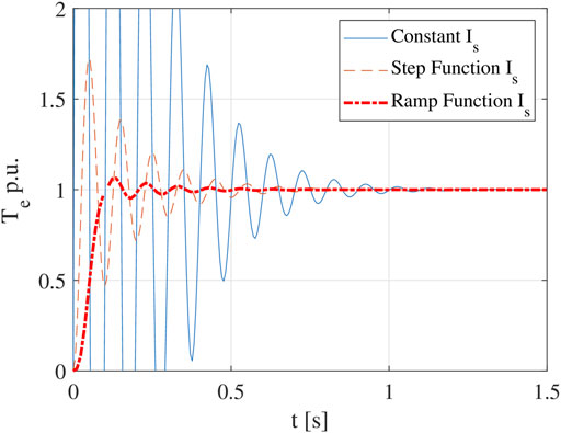
Performance of the three existing methods are evaluated with an example IM, when ωe = 2π × 510, τωslip = 30, and s = 0.0196, and the torque waveforms of the three methods are shown in Figure 2. It should be pointed out that for simplicity of initial discussion, the example uses an analytical model rather than a finite element model, so the nonlinear behaviors have not been considered yet.
Even though the ramp function Is method can significantly reduce the transient response time when compared with the other two methods, it still takes hundreds of cycles to reach the steady state. In fact, it takes much longer time to decay from 10 to 1% error than that from zero to 10% error.
3 Proposed Method—Multistep Equivalent Resistance Method
To further reduce the transient time, this article proposes the multistep equivalent resistance method. It is well known that as long as the value of
To implement the ER method, when Rr needs to be increased by a factor of kR, then the rotor bar resistivity and rotor slip should also be multiplied by kR, and the rotor mechanical speed should be modified as n* = n (1 − skR)/(1 − s).
To calculate the accurate IM performance, it is necessary to switch from the ER model back to the original model. Since the ramp function method has shown obvious advantages over the other two methods, if it can be combined with the ER method, the transient response time can be further reduced. Thus,
The relationship between τωslip and
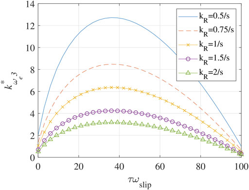
FIGURE 3. τωslip vs.
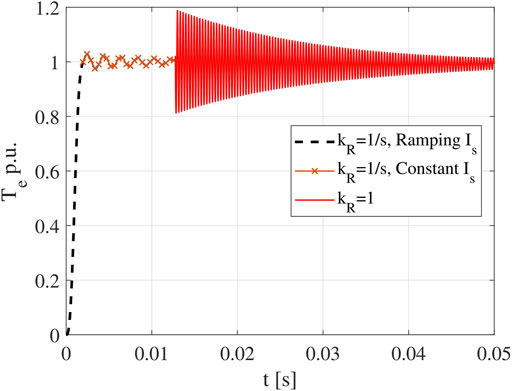
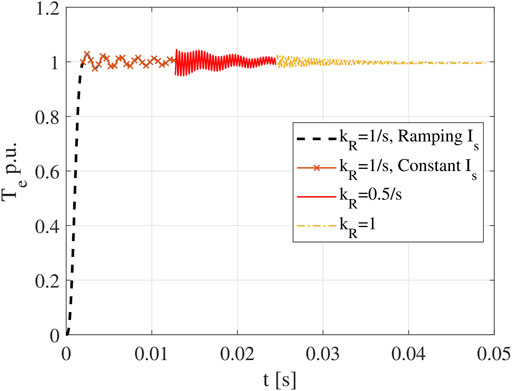
To mitigate this problem, the multistep ER method is proposed. The basic idea is to use a time-varying kR value to smooth the transition, such that tadd can be greatly reduced. As shown in Figure 4 (ωe = 2π × 510Hz and s = 0.0196), the one-step ER method will introduce large oscillation when the transition happens. While in Figure 5, when a two-step ER method is adopted, tadd becomes much shorter. It should be pointed out if the rotor speed is increased to the actual speed following a constant slope (ramp function) after the transition, it becomes a special case of the multistep ER method.
Note that Figures 4, 5 are schematic waveforms; the actual response of the finite element IM model involves complex nonlinear behavior that is difficult to be expressed by accurate analytical equations. Hence, the effectiveness of the proposed multistep ER method will be proven in the next section by the FEA model directly.
In short, the proposed method has two parts. First, stator current magnitude Is is increased following a ramp function and applied on q-axis while keeping the d-axis current to be zero (arbitrary synchronous reference frame). Second, a multistep equivalent resistance method is adopted.
4 Validation of the Proposed Method
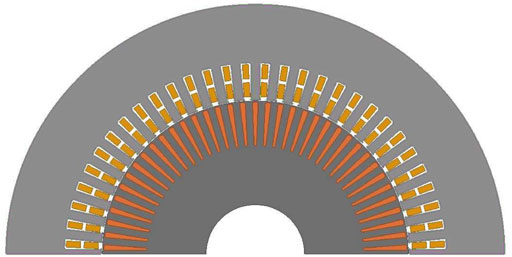
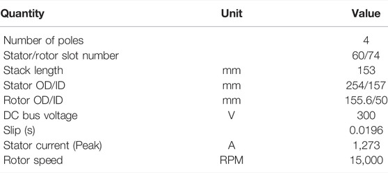
A high-speed traction IM is selected for investigation as shown in Figure 6 (cross section) and Table 1 (specs). For easiness of understanding, the steady state value of τωslip is calculated after the simulation, which is around 30. For the purpose of comparison, the transient response of different methods including the three existing methods discussed earlier is also calculated. The torque waveforms for constant Is and ramp function Is methods are shown in Figures 7, 8, respectively.
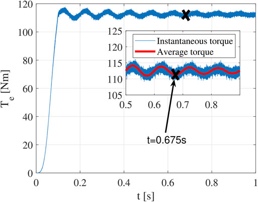
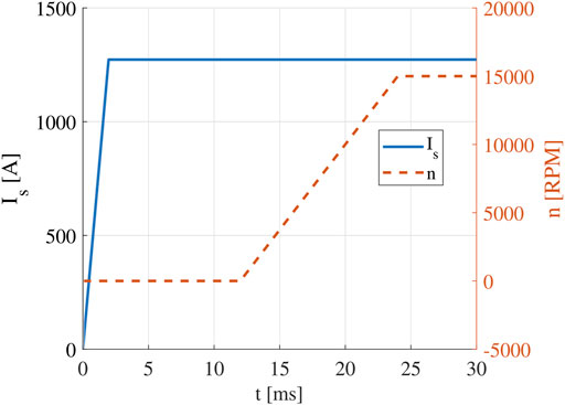
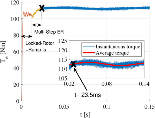
To validate the effectiveness of the multistep ER method, the rotor speed is increased from 0 to 15000RPM following a constant slope from t = 6tsyn = 11.8 ms to t = 12tsyn = 23.5 ms (Figure 9). The torque waveform is shown in Figure 10. It is found that there is almost no additional transient response after the rotor speed reaches 15000RPM. Hence, the total transient time is only 12tsyn (23.5 ms). As shown, the average value of the steady state torque is 112.5 N m.
The number of electrical cycle needed to reach 1% torque error is listed in Table 2. Since the constant Is method takes the longest time to reach the practical steady state (1%), its computation time is used as the reference for other methods. It is observed that the transient response time of the FEA models is longer than that of the theoretical analysis, which is the result of nonlinearity of the core material (saturation).
The finite element results show that the calculation time has been reduced from 2.877 s (constant Is method as shown in Figure 7) to 23.5 ms (proposed method as shown in Figure 10). Hence, the calculation time is reduced by more than 99% for the test case. In fact, this test case is a very challenging operating point in terms of finite element calculation, which is the maximum speed (15000 rpm) and low torque point. It is important to point out that the end time of calculation is decided by the most challenging and time-consuming points, rather than the average calculation time of all operating points. To be more specific, if the constant Is method takes 24 h to get the result, with the proposed method, the calculation time is reduced to less than 12 min.
Compared with the other two existing methods (step function Is method and ramp function Is method), the proposed method that combines the ramp function Is method and the multistep ER method can reduce transient response time by 98.9% and 96.5%, respectively.
5 Conclusion
A method to significantly accelerate the time-stepping magnetic transient FEA calculation of steady state performance of the high-speed traction IM is proposed. The proposed method includes two parts.
The first part is the ramp function Is method, which increases the stator current magnitude from zero to full magnitude following a constant slope, such that the DC component can be controlled at a very low level from the beginning. This part alone can reduce FEA calculation time by 76.5%.
The second part is the multistep equivalent resistance method, which adjusts the rotor resistance inversely proportional to the slip multiple times during the transient stage, such that the additional transient response due to the transition from the equivalent model to original model is suppressed to a negligible level.
Note that these two parts can work separately and together, either way can significantly reduce the FEA calculation time. The proposed method has two important features. First, the maximum electrical cycle needed to reach the steady state can be easily calculated before running the FEA model. Hence, the computation load and time are predictable. Second, the proposed method does not require knowing the parameter or feedback signal of the machine. Hence, its performance is very stable and robust.
The performance of the proposed method is validated by the FEA model of a typical high-speed traction IM. The result shows that the proposed method can reduce the FEA calculation time by 99%. Since the example calculation point is a very challenging test case, it is reasonable to believe that assuming error tolerance is 1%, the ramping up time of Is can be set at 6tsyn and the multi-step ER method can be set to increase the rotor speed gradually within 6tsyn, then the transient response time can be limited within 12tsyn in most cases.
Data Availability Statement
The raw data supporting the conclusion of this article will be made available by the authors, without undue reservation.
Author Contributions
HC: IM FEA model construction and writing the manuscript. RH and HZ: programming. HX, SL, and JX: literature review and writing the manuscript.
Funding
This work was supported by the Science and Technology Project of State grid Cooperation of China: Research on Harmonic Pollution of Non-Ideal AC Filter Inductor in V2G System and Countermeasures (5400-202099287A-0-0-00).
Conflict of Interest
HX, SL, and JX were employed by Nanjing Power Supply Company State Grid Jiangsu Electric Power Co., Ltd.
The remaining authors declare that the research was conducted in the absence of any commercial or financial relationships that could be construed as a potential conflict of interest.
Publisher’s Note
All claims expressed in this article are solely those of the authors and do not necessarily represent those of their affiliated organizations, or those of the publisher, the editors, and the reviewers. Any product that may be evaluated in this article, or claim that may be made by its manufacturer, is not guaranteed or endorsed by the publisher.
Acknowledgments
The authors would like to thank ANSYS Inc., for providing the finite element analysis tool Maxwell.
Abbreviation
Is, ids, iqs, stator current magnitude and dq components; idr, iqr, rotor current dq components; λdr, λqr, rotor flux dq components; Rs, Rr, stator resistance and rotor resistance; Ls, Lr, Lm, stator, rotor, and mutual inductance; tsyn, electrical synchronous period; ωe, synchronous angular frequency,
References
Cai, H. (2020). “A Fast Calculation Method for Steady State Performance of High Speed Traction Induction Machine by Finite Element Analysis,” in 2020 IEEE Energy Conversion Congress and Exposition (ECCE), 4284–4291. doi:10.1109/ECCE44975.2020.9236417
Di, C., Petrov, I., Pyrhonen, J. J., and Chen, J. (2019). Accelerating the Time-Stepping Finite-Element Analysis of Induction Machines in Transient-Magnetic Solutions. IEEE Access 7, 122251–122260. doi:10.1109/ACCESS.2019.2938269
El-Refaie, A. (2013). Motors/generators for Traction/propulsion Applications: A Review. IEEE Veh. Technol. Mag. 8, 90–99. doi:10.1109/MVT.2012.2218438
Fu, W. N., Ho, S. L., and Zhou, P. (2012). Reduction of Computing Time for Steady-State Solutions of Magnetic Field and Circuit Coupled Problems Using Time-Domain Finite-Element Method. IEEE Trans. Magn. 48, 3363–3366. doi:10.1109/TMAG.2012.2199285
Haghbin, S., Lundmark, S., Alakula, M., and Carlson, O. (2013). Grid-connected Integrated Battery Chargers in Vehicle Applications: Review and New Solution. IEEE Trans. Ind. Electron. 60, 459–473. doi:10.1109/TIE.2012.2187414
Khaligh, A., and D'Antonio, M. (2019). Global Trends in High-Power On-Board Chargers for Electric Vehicles. IEEE Trans. Veh. Technol. 68, 3306–3324. doi:10.1109/TVT.2019.2897050
Kim, Y., Koo, B., and Nam, K. (2019). Induction Motor Design Strategy for Wide Constant Power Speed Range. IEEE Trans. Ind. Electron. 66, 8372–8381. doi:10.1109/TIE.2018.2885691
Le Besnerais, J., Fasquelle, A., Hecquet, M., Pelle, J., Lanfranchi, V., and Harmand, S. (2010). Multiphysics Modeling: Electro-Vibro-Acoustics and Heat Transfer of Pwm-Fed Induction Machines. IEEE Trans. Ind. Electronics 57, 1279–1287. doi:10.1109/TIE.2009.2029526
Lin, D., Zhou, P., Chen, N., Lu, C., and Christini, M. (2017). “Fast Methods for Reaching Ac Steady State in Fe Transient Analysis,” in 2017 IEEE International Electric Machines and Drives Conference (IEMDC), 1–6. doi:10.1109/IEMDC.2017.8001996
Metwly, M. Y., Abdel-Majeed, M. S., Abdel-Khalik, A. S., Hamdy, R. A., Hamad, M. S., and Ahmed, S. (2020). A Review of Integrated On-Board Ev Battery Chargers: Advanced Topologies, Recent Developments and Optimal Selection of Fscw Slot/pole Combination. IEEE Access 8, 85216–85242. doi:10.1109/ACCESS.2020.2992741
Rainer, S., Biro, O., Stermecki, A., and Weilharter, B. (2012). Frequency Domain Evaluation of Transient Finite Element Simulations of Induction Machines. IEEE Trans. Magnetics 48, 851–854. doi:10.1109/TMAG.2011.2173164
Wang, Z., Zhang, Y., You, S., Xiao, H., and Cheng, M. (2020). An Integrated Power Conversion System for Electric Traction and V2g Operation in Electric Vehicles with a Small Film Capacitor. IEEE Trans. Power Electronics 35, 5066–5077. doi:10.1109/TPEL.2019.2944276
Xiao, Y., Liu, C., and Yu, F. (2019). An Integrated On-Board Ev Charger with Safe Charging Operation for Three-phase Ipm Motor. IEEE Trans. Ind. Electronics 66, 7551–7560. doi:10.1109/TIE.2018.2880712
Yamazaki, K., Kuramochi, S., Fukushima, N., Yamada, S., and Tada, S. (2012). Characteristics Analysis of Large High Speed Induction Motors Using 3-d Finite Element Method. IEEE Trans. Magnetics 48, 995–998. doi:10.1109/TMAG.2011.2172919
Keywords: finite element, induction machine, torque, transient response, high-speed, equivalent resistance, V2G, harmonic
Citation: Cai H, Huang R, Zhai H, Xu H, Liu S and Xu J (2022) Fast and Accurate Traction Induction Machine Performance Calculation Method for Integrated Onboard Charging in Vehicle to Grid Application. Front. Energy Res. 10:875706. doi: 10.3389/fenrg.2022.875706
Received: 14 February 2022; Accepted: 01 March 2022;
Published: 01 April 2022.
Edited by:
Qingxin Shi, North China Electric Power University, ChinaCopyright © 2022 Cai, Huang, Zhai, Xu, Liu and Xu. This is an open-access article distributed under the terms of the Creative Commons Attribution License (CC BY). The use, distribution or reproduction in other forums is permitted, provided the original author(s) and the copyright owner(s) are credited and that the original publication in this journal is cited, in accordance with accepted academic practice. No use, distribution or reproduction is permitted which does not comply with these terms.
*Correspondence: Haiwei Cai, aGFpd2VpY2FpQHNldS5lZHUuY24=
 Haiwei Cai
 Ru Huang1