 Haipeng Lv
 Xiwang Abuduwayiti*
94% of researchers rate our articles as excellent or good
Learn more about the work of our research integrity team to safeguard the quality of each article we publish.
Find out more
ORIGINAL RESEARCH article
Front. Energy Res. , 25 October 2021
Sec. Process and Energy Systems Engineering
Volume 9 - 2021 | https://doi.org/10.3389/fenrg.2021.768340
This article is part of the Research Topic Advanced Technologies for Planning and Operation of Prosumer Energy Systems View all 111 articles
Owing to the increased proportion of new energy power generation, such as wind power and photovoltaics, connected to the island grid, the system powered by the voltage source converter-based HVDC (VSC-HVDC) is prone to oscillate or even lose stability when disrupted. In this study, considering the rapid power compensation (RPC), an active power control strategy has been suggested for the receiving-end converter station of VSC-HVDC that could efficiently suppress the low-frequency oscillation of the island power system. First, the mechanism of VSC-HVDC inhibiting low-frequency oscillation of the island grid is analyzed in this study, and then, it theoretically determines that the damping capacity and inertia level of the rapid power compensation control strategy are stronger than those of conventional droop control and inertia control. Second, the receiving-end converter station switches from the RPC mode to droop control in order to allow the system to have a smooth recovery from the steady-state operation in the later stage of oscillation suppression. Moreover, detailed control logic and state-switching strategies have been designed. Finally, the simulation reflects that the proposed control strategy has a stronger oscillation suppression ability, allowing it to obtain rapid suppression of low-frequency oscillation.
The internal load of the island is increasing in tandem with the rapid rise of the scale of offshore drilling platforms and the development of the island. When the island’s configured power supply including wind power, photovoltaics, and synchronous generators (SGs) is unable to meet the increased load, the transmission mode of power supply from the bulk power grid to the island grid through VSC-HVDC gets more attention (Wang et al., 2020; Lan et al., 2021; Zhang et al., 2021). Meanwhile, the growing proportion of wind power and photovoltaics linked to the island grid poses a series of challenges to the island grid’s steady functioning, particularly in low-frequency oscillations (Zhou W. et al., 2020; Erdiwansyah et al., 2021). For this purpose, determining how to suppress low-frequency oscillation fast and effectively while also improving power supply reliability has become a significant research topic (Huang et al., 2021).
In order to suppress low-frequency oscillation, a variety of solutions have been proposed. The typical method is the installation of a power system stabilizer (PSS) to the SG’s excitation regulator to give positive damping torque for generators (Bhukya and Mahajan, 2019; Liu et al., 2020). However, the relevant research indicates that PSS is not always efficient for low-frequency oscillation, mainly in interval oscillation (Oscullo and Gallardo, 2020). Furthermore, the energy storage device is considered an effective way to enhance the security and stability of the power grid. While compensating for imbalanced power in the island grid, the energy storage device can efficiently suppress low-frequency oscillation due to its flexible control modes and rapid response (Ersdal et al., 2020). However, the high cost of the energy storage device configuration will lower the operational economy of the island grid. With the rapid advancement in the new energy power generation technology, more and more experts are making efforts to use wind power and photovoltaics to suppress the oscillation after adjusting their active power output, which does not require an additional hardware configuration (Chen et al., 2021). However, this method requires a large capacity of the reserve, which significantly reduces the usage rate of wind power and photovoltaics (Zhang et al., 2019). In addition, wind power and photovoltaics are both heavily influenced by wind speed and light intensity, respectively, and thus, their available adjustment capacity cannot be guaranteed (Singh, 2017).
The VSC-HVDC technology provides control flexibility, allowing the converter station to quickly switch the operation mode. By adding a damping control link to the active or reactive power control of the original device, VSC-HVDC can offer positive damping for the system to suppress the low-frequency oscillation of the AC side (Saadatmand et al., 2019; Zeng et al., 2019). Currently, adding damping control to the original control structure is a common idea (Xu et al., 2020). Therefore, the additional damping control based on VSC-HVDC has been extensively researched, particularly in the damping interval oscillation, which has a more flexible control mode and rapid response than the traditional damping control (Huang et al., 2019a; Shao et al., 2021).
In the case of an AC/DC hybrid grid with VSC-HVDC, the active and reactive powers of the VSC-HVDC converter may be adjusted by designing additional controllers, which can effectively suppress the inter-regional low-frequency oscillation and enhance the dynamic performance of the system. Moreover, by using state feedback, Ni et al. (2019) proposed a supplementary damping controller of multiterminal HVDC systems based on voltage source converters (VSC-MTDC), which can produce supplementary control signals and regulate the active power of each converter to suppress the system oscillation. An adaptive supplementary damping controller was also proposed by Shen et al. (2017) on the basis of the goal representation heuristic dynamic programming, which reflects good damping characteristics in inter-area low-frequency oscillation suppression. It encompasses rapid online learning capability and does not require building a mathematical model of a power system. However, it was determined that the supplementary damping controller can effectively suppress the low-frequency oscillation of VSC-MTDC by using a coordinated design method based on the concept of eigenvalue sensitivity (Renedo et al., 2021). In order to study the damping control mechanism of low-frequency oscillation, damping torque analysis can be proved as an effective method for analysis. Zhou T. et al. (2020) further used the analysis theory to design the VSC-HVDC additional damping controller, which can significantly enhance the dynamic stability of the AC/DC system.
The abovementioned control strategies have a relatively weak response ability to the AC system in the early stage of low-frequency oscillation, as evidenced by two factors: 1) the available positive damping is small and 2) the decay period of the low-frequency oscillation is relatively long. Therefore, it is high time to suggest a suitable fast damping technology to suppress oscillation in the VSC-HVDC systems. In this study, an RPC strategy has been proposed for the receiving-end converter of VSC-HVDC to suppress low-frequency oscillations of the island grid. In the early stage of oscillation, a convertor maintains the active power at the power limit by increasing or decreasing it to quickly compensate for an unbalanced power of the system. In the later stage, the droop control is employed for smoothly switching toward the steady-state operation. The key contributions of this article are presented as follows:
1) The mechanism of suppressing the low-frequency oscillation of the island grid by VSC-HVDC is theoretically investigated. To be specific, the electromagnetic power of the SG may be changed indirectly by adjusting the active power of the VSC-HVDC receiving-end converter.
2) It is proved that the RPC approach suggested in this study has a better inhibitory capacity on the rotor speed deviation Δω of SG and the rate of change of rotor speed dω/dt than conventional droop control and inertia control.
3) A comprehensive switching strategy for each mode is suggested by examining the switching mechanism of the control strategy combining RPC with droop control.
4) The simulation confirms that the proposed strategy can effectively suppress the low-frequency oscillations of the island grid.
The rest of the article is organized as follows: Section 2 analyzes the detailed mechanism of VSC-HVDC suppressing low-frequency oscillation in the island grids. Based on it, Section 3 investigates the performance of different VSC-HVDC suppression strategies. Section 4 describes the implementation of a control strategy combining RPC with the droop control. Section 5 verifies the effectiveness of the proposed control method. Finally, conclusions are drawn in Section 6.
This study examines the effect of the active power output of the VSC-HVDC inverter side converter station on electromagnetic power of SG in the island grid by considering the application scenario of VSC-HVDC to suppress the low-frequency oscillation of the island grid as an example. Among them, the bulk power grid as a sending end has a high capacity and excellent anti-interference capabilities, but the island grid as a receiving end has a small capacity and weak stability, making it prone to low-frequency oscillations when disrupted. In this case, the bulk power grid can offer active support to the island grid for suppressing its low-frequency oscillation.
Figure 1 mainly includes the bulk power grid, VSC1 (sending-end converter station onshore), VSC2 (receiving-end converter station on the island), submarine cables, the island grid, the prime motor, T1 (transformer of the VSC-HVDC sending end), T2 (transformer of the VSC-HVDC receiving end), and SG. Z0, Z1, and Z2 are the equivalent impedances of the line. The line voltages of the AC side of VSC2, the island grid, and the SG are V, U, and E, respectively. VDC depicts the DC side voltage of VSC-HVDC. P0 and PE are the steady-state power and compensation power of VSC2, respectively. Id and Iq are the d-axis current and q-axis current of VSC2 in the dq-axis coordinate system, respectively. δ is the power angle of the SG, and θ is the phase of the line voltage, U.
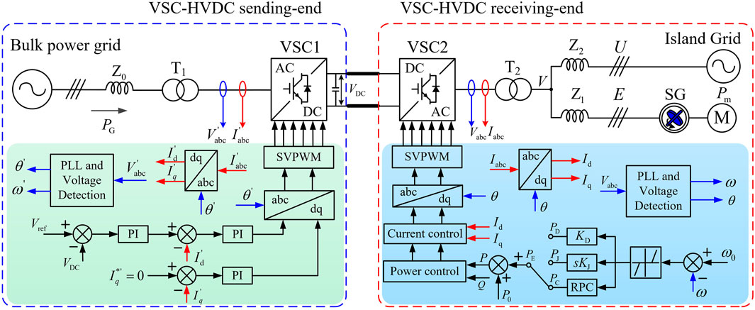
FIGURE 1. Application scenario of VSC-HVDC to suppress low-frequency oscillation of the island grid.
This study has considered the constant DC voltage control method to maintain the constant DC voltage on the rectifier side of VSC-HVDC. Meanwhile, on the inverter side, the constant active power control method is employed to offer active support for the island grid. This study does not include the constant voltage control strategy of the rectifier side as it is not the research area. When the island grid experiences low-frequency oscillation, VSC2 injects an adjustable active power into the island grid by monitoring the frequency and equivalent signal of the SG in order to restore the speed of SG to the rated value. Given that the dynamic process of low-frequency oscillation belongs to the second-level electromechanical time scale, whereas the response process of a fully controlled PWM inverter happens on the millisecond-level electromagnetic time scale, the VSC-HVDC system can be regarded as a controlled current source that outputs a controllable current according to the needs of the oscillation suppression. Further, the physical system model presented in Figure 1 is simplified, as shown in Figure 2.
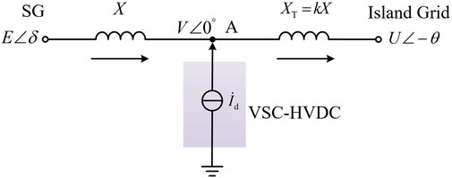
FIGURE 2. Simplified system model.
Figure 2 reflects that X is the line-equivalent impedance between grid-connected node A and SG (i.e., X = Z1) and XT is the line-equivalent impedance between A and the island grid (i.e., XT = Z2). The electromagnetic power of SG can be described as the following:
The active power absorbed by the island grid can be expressed as
Hence, the KCL equation of node A in Figure 2 is given by the following:
where Id is the active output current of VSC2.
The real and imaginary sections of Eq. 3 can be presented as
Combining Eqs 4, 5, we will have
Linearizing Eq. 6, the resulting equation is as follows:
where Id0 is the rated output current of VSC2.
The simplified model of the system, shown in Figure 2, reflects that the voltage V at the grid-connected node A is influenced by the power angle δ of SG and the output current Id of VSC2. Therefore, the δ and Id in Eq. 7 are perceived as independent variables and V as a dependent variable. Furthermore, the equation is as follows:
Substituting Eq. 8 into a linearized Eq. 1, the resulting equation is as follows:
After simplifying Eq. 9, the result is as follows:
where Kg and Ke are the synchronization coefficient of the grid and the control coefficient of VSC2, respectively, which are solely linked with the structures, parameters, and working points of the system. Consequently, in the case of low-frequency oscillation, the electromagnetic power of SG can be adjusted through the active current of VSC2. Therefore, it is necessary to suggest an efficient active control strategy for VSC-HVDC for suppressing the low-frequency oscillation.
As shown in Figure 3, in order to assess the effect of oscillation suppression, there are three key indexes, including the rotor speed deviation Δω of SG, the rate of change of rotor speed dω/dt, and the rotor oscillation area Sω, when the low-frequency oscillation starts appearing in the island grid. Among them, the calculation method of Sω is described in Eq. 13. Therefore, it is necessary to suppress the low-frequency oscillation of the island grid with the three following aspects: 1) suppress Δω to avoid stall of SG, 2) restrain dω/dt to avoid mechanical damage of the SG rotor, and 3) suppress Sω to avoid an excessive oscillation duration and amplitude.
where ω0 is the synchronous speed of SG.
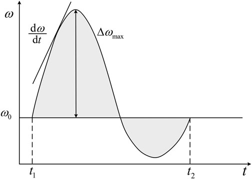
FIGURE 3. Dynamic evaluation index of the rotor speed.
If VSC-HVDC provides active support to the island grid, the damping coefficient TD and the inertia coefficient TJ of the island grid (Zhu et al., 2019) are as follows:
where D and H are the inherent damping and inertia coefficient, respectively. Kp and Kd are the droop and inertia controller gains, respectively.
In order to suppress the low-frequency oscillation of the island grid, the existing control strategy of VSC-HVDC is mainly divided into droop control (damp control) and inertia control. Eqs 14, 15 reflect that the control effect of the P controller and D controller is equivalent to damping control and inertia control, respectively. By increasing Kp, the damping coefficient TD of the island grid will also go up and VSC2 will provide more damping torque to the island grids, which will effectively suppress the Δω. Similarly, by increasing the Kd, the inertia coefficient TJ will go upward as well. To suppress dω/dt, VSC2 will provide more inertia support. Thus, the above analysis reflects that the adjusting gain of the PD controller can equivalently change Sω.
Therefore, consider VSC2 working in the droop control mode as an instance to assess the effect of Kp on the output power of VSC2. As illustrated in Figure 4A, the island grid exhibits a low-frequency oscillation at time t0, and the time period t1-t2 is selected for description in the article. Figures 4A–C depicts the decline in the speed of SG during the period t1-t2 and the absolute value of dω/dt monotonously. Therefore, VSC2 is required to enhance the active power for compensating the power shortage of the island grid, which will weaken the process of low-frequency oscillation to make the island grid come back into a steady state. Equation 16 represents that PD will significantly go up with an increase in Kp, and its damping effect on the system will further improve. The continuous increase in Kp will make PD reach saturation quickly, and it will be impossible to further improve the compensation capability of VSC2 by adjusting Kp, as reflected in Figure 4D.
where PD and PJ are the active power of VSC2 under droop and damping control, respectively. s is the derivative operator.
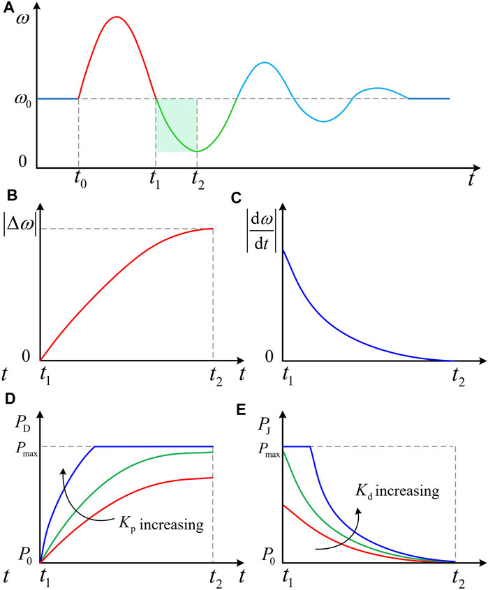
FIGURE 4. Effect of control parameters on inertia control and droop control when frequency falls: (A) rotor speed change of SG; (B) absolute value of rotor speed deviation; (C) absolute value of the change rate of rotor speed; (D) the effect of Kp on PD; (E) the effect of Kd on PJ.
Similarly, when VSC2 is in the inertia control mode, PJ will go up noticeably with an increase of Kd, as shown in Eq. 17. Meanwhile, Figure 4E reflects that the increase of Kd will shift the power curve of VSC2 upward. Due to low reserve capacity, PJ will be limited to maximum power Pmax if the trend continues.
In summary, the impact of droop control and inertia control of VSC2 is amplified to the limit when Kp and Kd approach a certain limit. VSC2 will increase or decrease active power alternately with maximum power Pmax or 0. This study considers this working mode of VSC2 as the RPC.
In order to compare the advantages of RPC with the traditional droop and inertia control in control performance, the following derivation is presented:
1) RPC mode: when the island grid runs in a steady-state operation, the active power PVSC2 provided by VSC2 is equal to the active power PIG absorbed by the island grid (i.e., PVSC2 = PIG), resulting in the following:
Assume that the load power of the island grid suddenly increases ΔPL at a certain time, causing low-frequency oscillation of the island grid. Simultaneously, the imbalanced power Pim will no longer be 0, requiring VSC2 to deliver additional power PE to compensate for the power shortage of the system. As indicated in Eq. 19, the output power of VSC2 will then consist of steady-state power P0 and compensation power PE.
Since the load of an asynchronous motor in the island grid will automatically raise its loss of power with the increase of system frequency (Huang et al., 2019b), PIG will include the steady-state load PL0, ΔPL and KL (ω0 − ω), as illustrated in Eq. 20.
where KL is the intrinsic frequency response coefficient of the island grid.
Then, substituting Eqs 19, 20 into Eq. 18, it is equal to
When the island grid runs on the steady mode, P0 is equal to PL0, and Eq. 21 will be revised as
If the RPC strategy is used to suppress the low-frequency oscillation (i.e., PE = ΔPmax), Eq. 22 can be rewritten as
where ΔPmax is the maximum power that VSC2 can compensate.
Solving the first-order non-homogeneous linear differential equation as shown in Eq. 23, it is equal to the following:
2) Droop control mode: when using droop control to suppress low-frequency oscillation, substituting PE = Kp(ω0 − ω) into Eq. 22, we will get the following:
By solving the first-order non-homogeneous linear differential Eq. 26, the expression of Δω and dω/dt will receive as Eqs 27, 28.
Due to the power limitation of VSC2, the PE will obtain the maximum power when Δω reaches the highest value, as presented in Eq. 29.
Then, Kp can be described as
By substituting Eq. 30 into Eq. 27, the result is as follows:
Comparing Eq. 31 with Eq. 24, the equation is as follows:
Similarly, by combining Eq. 28 and Eq. 25, it holds the following:
Equations 32, 33 demonstrate that RPC can suppress Δω and dω/dt better than droop control. Similarly, it shows that RPC has a stronger ability than inertia control (Xiong et al., 2021).
Although the RPC mode can suppress low-frequency oscillation better than droop control and inertia control, VSC2 should not be used in the RPC mode for an extended period. The RPC mode may induce overcompensation when the oscillation amplitude can effectively control in the late period of low-frequency oscillation suppression. The inertia control is mainly used to suppress dω/dt due to its lower suppression ability to Δω; this study considers droop control to realize the VSC2 smooth exiting RPC mode. Based on the above analysis, a low-frequency oscillation suppression strategy combining RPC with droop control has been proposed in this study. In the early stage of low-frequency oscillation, the RPC is used to rapidly suppress Δω and dω/dt, while in the later stage of the low-frequency oscillation, since the amplitude of the oscillation is fully controlled, it switches smoothly to steady-state operation using the droop control. Figure 5 presents a schematic diagram of the SG’s speed curve and the power compensation curve of VSC2 in the case of low-frequency oscillation. Also, the whole process includes four operating modes. Figure 6 contains the control block diagram combining RPC with droop control. Since VSC2 only offers active power support in this study, let the instruction value of the q-axis current be 0 (i.e.,
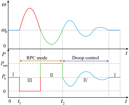
FIGURE 5. Speed of SG and the compensation power of VSC2.
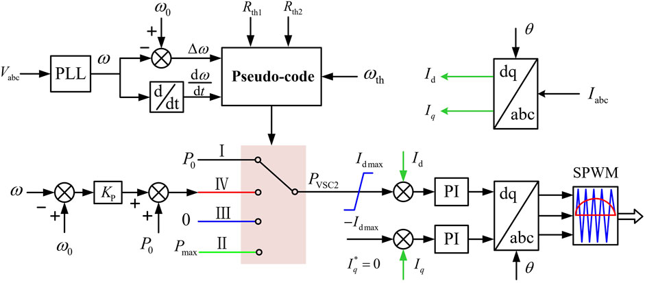
FIGURE 6. Control block diagram combining RPC with droop control.
Mode I: Steady-state operation mode. If Δω and dω/dt satisfy
Mode II: Positive RPC mode. If dω/dt < − Rth2 and
Mode III: Negative RPC mode. Contrary to mode II, if dω/dt > Rth2 and
Mode IV: Droop control mode. If Rth1 < dω/dt < Rth2 or − Rth2 < dω/dt < − Rth1 and
The mode switching logic is described by a pseudo-code, in detail, as follows:
begin
Define the zero-crossing threshold of the speed deviation, ωth.
Define the threshold Rth1 and Rth2 for variables dω/dt.
Define the working mode variable, mode, and initialize mode = 1.
Define the state machine variable, step, and initialize step = 1.
Input Δω and dω/dt
while (ω == ωth)
1) If the switching condition of RPC is met when low-frequency oscillation occurs, the following logical structure will inevitably be entered.
if (dω/dt < − Rth2 &&
mode = 2. Switch to mode II.
step = 2. State machine switches to RPC state.
elseif (dω/dt > Rth2 &&
mode = 3. Switch to mode III.
step = 2. State machine switches to RPC state.
elseif ((Rth1 < dω/dt < Rth2) ‖ (−Rth2 < dω/dt < − Rth1))&&
mode = 4. Switch to mode IV.
step = 3. State machine switches to droop control state.
elseif
mode = 1. Switch to mode I.
step = 1. State machine switches to steady-state operating state.
endif
2) If the RPC switching condition is not satisfied when the low-frequency oscillation occurs, it will inevitably enter the following droop control logic structure:
if ((Rth1 < dω/dt < Rth2) ‖ (−Rth2 < dω/dt < − Rth1))&& (
mode = 4. Switch to mode IV.
step = 3. State machine switches to droop control state.
endif
end while
end
In this study, the state machine is configured to achieve the unidirectional transition from steady-state operation (i.e., step = 1) to the RPC mode (i.e., step = 2), then to the droop control mode (i.e., step = 3), and finally back to steady-state operation. While suppressing oscillation, just a sole detection is conducted in the small neighborhood after the zero-crossing Δω to avoid the consumption of CPU resources in real-time detection.
The basic control idea behind the strategy proposed in this study can be described as the following:
1) The control strategy combining RPC with droop control. If the switching criteria of the RPC model are fulfilled by Δω and dω/dt during the early stage of the oscillation, the state machine will definitely switch from step 1 to 2. Afterward, the state machine will switch from step 2 to 3, when the oscillation decays to match the droop control switching criteria. At last, the state machine will move from step 3 to 1 after the oscillation completely suppresses.
2) Droop control works alone. When the island grid is less disrupted (i.e., Δω and dω/dt do not meet the switching criteria of the RPC mode), the oscillation will be directly suppressed through the droop control. Meanwhile, the state machine switches from step 1 to 3 and finally gets back to step 1.
Considering the MATLAB/Simulink, a simulation model of the receiving-end island grid containing the VSC-HVDC transmission system was built, with an aim to assess the efficiency of the control strategy proposed in this study. The performance of the control strategy combining RPC with droop control and inertia control was compared and evaluated. Figure 1 reflects the simulation topology, and the main parameters are shown in Tables 1, 2. Assume that the load mutation is set at 3 s, an obvious low-frequency oscillation will occur in the island grid, and then, the oscillation will suppress by the proposed strategy.
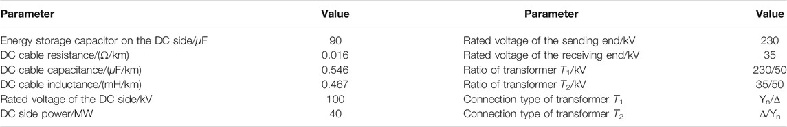
TABLE 1. Main parameters of VSC-HVDC.
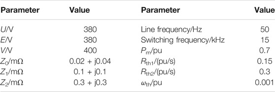
TABLE 2. Other related parameters of the system.
By increasing Kp, the suppression effects of different droop control modes on low-frequency oscillation are compared and analyzed. In addition, as shown in Figures 7, 8, the rotor speed characteristics of SG under the aforementioned control mode and the control strategy combining RPC with droop control are compared.
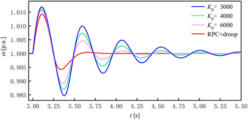
FIGURE 7. Rotor speed dominated by droop control modes.
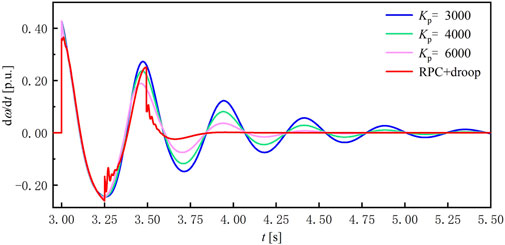
FIGURE 8. Rate of change of rotor speed dominated by droop control modes.
It can be seen from Figures 7, 8 that by increasing Kp, the oscillation amplitude of the SG rotor goes down gradually, while there is no significant impact on the oscillation period. Therefore, increasing Kp can enhance the damping ability of the island grid and then effectively suppress Δω. However, there is no significant improvement in the inertial level of the system. The control strategy combining RPC with droop control not only lowers the rotor speed deviation of the SG but also reduces the oscillation period of the system, allowing the island grid to quickly recover into steady-state operation.
The curve of the three-phase output current of VSC2 under different droop control modes can be seen in Figure 9. It is clear that when the rotor speed goes up, the output current of VSC2 will reduce under droop control. On the other hand, when the rotor speed decreases, VSC2 will raise the output current rapidly to compensate for the power shortage of the system. By increasing Kp, the output current of VSC2 also goes up drastically. When Kp = 6,000, since VSC2 has reached the upper limit of power output, the local period is pushed to limit the amplitude. However, as shown in Figure 9C, the damping level of the island grid has improved.
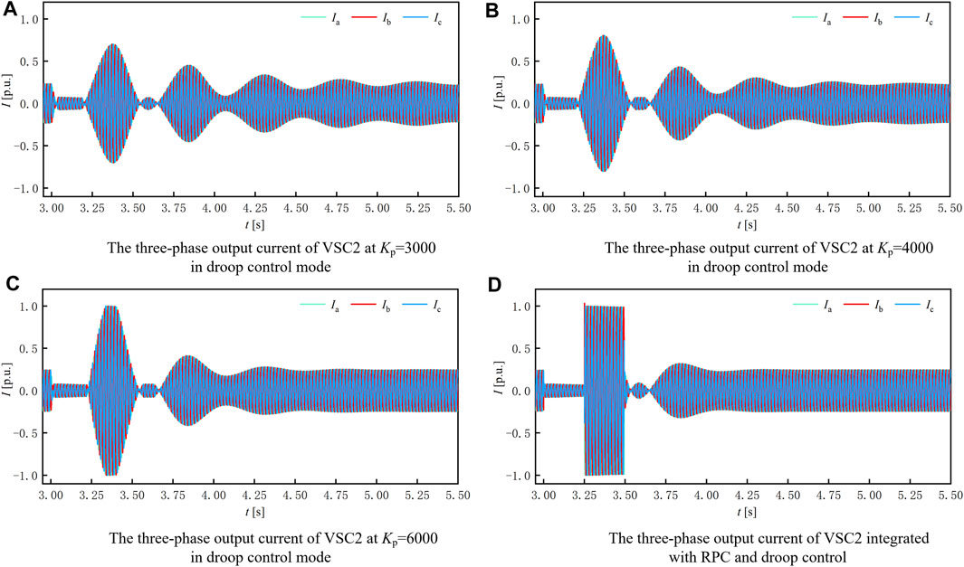
FIGURE 9. Three-phase output current of VSC2 under different droop control modes.
It can be seen from Figure 9D that VSC2 rapidly suppresses low-frequency oscillations under the RPC control strategy in the first cycle of oscillation. Therefore, the Δω and dω/dt can be effectively inhibited during the early stage of oscillation. Afterward, by switching to the droop control mode in the later period of the oscillation, VSC2 smoothly leaves the RPC control mode for restoring the island grid into steady-state operation.
Therefore, the suppression effect of the individual droop control on low-frequency oscillation is not an ideal approach. The combined control strategy proposed in this study can maximize the oscillation suppression ability of VSC2 and significantly enhance the damping capacity and inertia level of the system.
By changing Kd, the impacts of different inertia control modes on low-frequency oscillation are compared and evaluated. Furthermore, as shown in Figures 10, 11, the rotor speed characteristics of SG under the different inertia control modes and the control strategy combining RPC with inertia control are compared.
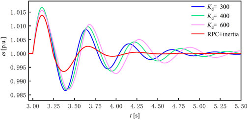
FIGURE 10. Rotor speed dominated by inertia control modes.

FIGURE 11. Rate of change of rotor speed dominated by inertia control modes.
By combining Figures 10, 11, it is determined that increasing Kd causes the curve of rotor speed and the rate of change of rotor speed to move to the right but has no discernible inhibitory impact on the amplitude of low-frequency oscillation. As a result, an individual inertia control is unable to swiftly restore SG’s speed to the synchronous speed. However, with respect to the low-frequency oscillation suppression, the control strategy combining RPC with inertia control is obviously superior to the individual inertia control. This is mainly because VSC2 suppresses low-frequency oscillation with a power limit when it switches to II and III modes in 3–3.5 s, and also, the rotor speed deviation and the rate of change of rotor speed get significantly improved. The control strategy combining RPC with inertia control in Figure 10 allows the island grid to recover into steady-state operation at 4.5 s, while control strategy combining RPC with droop control in Figure 7 can fully suppress the oscillation at 3.8 s, which shortens the oscillation attenuation period by 15.5%. Therefore, the proposed control strategy combining RPC with droop control can suppress oscillation better.
Figure 12 represents the curve of the three-phase output current of VSC2 under different inertia control modes. It is a fact that with an increase in Kd, the output current of VSC2 also goes up significantly. Also, when the output current of VSC2 is increased to 600, as illustrated in Figure 12C, it is pushed to a limit in local periods. Nonetheless, the inertia level of the island grid has considerably improved, making it easier to suppress the low-frequency oscillation.
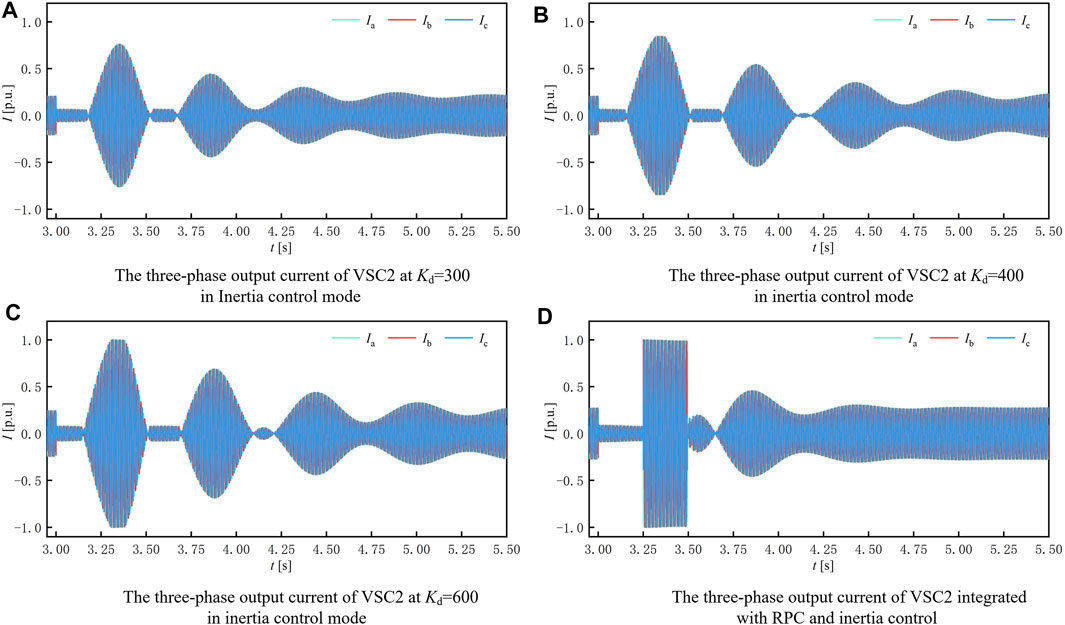
FIGURE 12. Three-phase output current of VSC2 under different inertia control modes.
By comparing Figure 9D with Figure 12D, it can be derived that since the two combined control strategies are both in the RPC mode from 3.0 to 3.5 s, the output current of VSC2 is similar under the two combined control strategies in this period. After the switching of 3.5 s to mode IV, due to the weak damping characteristics of inertia control, the output current of VSC2 requires to get adjusted through several cycles for completing the suppression of oscillation, while the droop control can fulfill the suppression of low-frequency oscillation rapidly. Therefore, the proposed combined control strategy considers droop control as a state transition strategy in mode IV.
In order to further verify the damping effect of the control strategy proposed in this study, it is compared with the additional damping control based on state feedback (SF-SDC), adaptive additional damping control (ASDC), and additional damping control based on damping torque analysis (DTA-SDC) described above. The rotor speed characteristics are shown in Figures 13, 14.
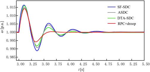
FIGURE 13. Rotor speed under the state-of-the-art suppression methods.
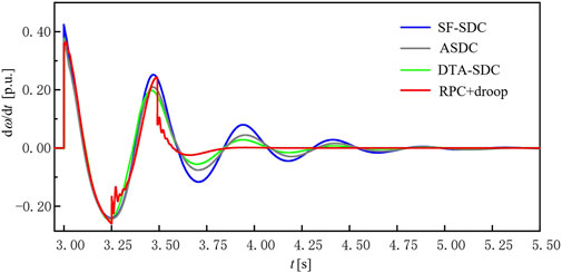
FIGURE 14. Rate of change of rotor speed under the state-of-the-art suppression methods.
It can be seen from Figures 13, 14 that SF-SDC, ASDC, and DTA-SDC have terrific inhibitory effects on low-frequency oscillation so that the oscillation is basically attenuated at 4.75, 4.70, and 4.50 s, respectively. The combined control strategy proposed in this study makes the low-frequency oscillation decay rapidly in the initial stage of oscillation, and the dynamic performance of the system is significantly improved; the oscillation was completely suppressed at 3.8 s, whose attenuation period was shortened by 20, 19, and 15.5% compared with the above three methods.
Although the above three control methods have their own unique advantages, the combined control strategy has obvious superiority in the response speed to low-frequency oscillation. In summary, the control strategy combining RPC with droop control can quickly suppress Δω and dω/dt and shorten the oscillation cycle, allowing the SG rotor speed to rapidly recover to synchronous speed.
Considering the issue of low-frequency oscillation suppression of the island power system supplied by VSC-HVDC, the suppression of oscillation of the island power system by adjusting the active power output of the VSC-HVDC receiving-end converter station is made. Moreover, in order to enhance the damping ability and the inertia level of the system simultaneously, an active power control strategy based on RPC is suggested. As a whole, the following conclusions are drawn from the whole analysis:
1) In contrast to the conventional droop and inertia control, the RPC control strategy suppresses the Δω and dω/dt more effectively. In other words, it contains a rapid response speed and a shorter attenuation time for low-frequency oscillation, which is consistent with the corresponding theoretical demonstration in this study.
2) By combining RPC with droop control, the island power system may achieve the maximum power response of VSC2 during the early stage of oscillation and then seamlessly switch to steady-state operation after applying effective control of Δω and dω/dt. The proposed strategy shortens the oscillation attenuation period by 15.5% compared with the strategy combining RPC with inertia as well as 20, 19, and 15.5% compared with SF-SDC, ASDC, and DTA-SDC methods, which has stronger damping characteristics for low-frequency oscillations.
Furthermore, the proposed control strategy combining RPC with droop control is primarily focused on active power control and the VSC-HVDC system that allows to adopt active and reactive power decoupling control. Therefore, the author will investigate the reactive power control based on VSC-HVDC to suppress low-frequency oscillation in the future, extending the advantages and potential of VSC-HVDC.
The original contributions presented in the study are included in the article/Supplementary Material; further inquiries can be directed to the corresponding author.
Investigations: HL and XA; methodology: HL, XA, and LM; project administration: CS and LM; resource: HL and XA; software: HL and XA; supervision: LM and CS; validation: HL and XA; visualization: HL, XA, and LM; writing—original draft: HL and XA; writing—review and editing: HL and XA.
The authors declare that the research was conducted in the absence of any commercial or financial relationships that could be construed as a potential conflict of interest.
All claims expressed in this article are solely those of the authors and do not necessarily represent those of their affiliated organizations or those of the publisher, the editors, and the reviewers. Any product that may be evaluated in this article or claim that may be made by its manufacturer is not guaranteed or endorsed by the publisher.
Bhukya, J., and Mahajan, V. (2019). Mathematical Modelling and Stability Analysis of PSS for Damping LFOs of Wind Power System. IET Renew. Power Generation. 13, 103–115. doi:10.1049/iet-rpg.2018.5555
Chen, M., Zhou, D., and Blaabjerg, F. (2021). Active Power Oscillation Damping Based on Acceleration Control in Paralleled Virtual Synchronous Generators System. IEEE Trans. Power Electron. 36, 9501–9510. doi:10.1109/tpel.2021.3051272
Erdiwansyah Mahidin, , Husin, H., Nasaruddin, Zaki, M., and Muhibbuddin, (2021). A Critical Review of the Integration of Renewable Energy Sources with Various Technologies. Prot. Control. Mod. Power Syst. 6, 1–18. doi:10.1186/s41601-021-00181-3
Ersdal, A. M., Gonzalez-Longatt, F., Acosta, M. N., Rueda, J. L., and Palensky, P. (2020). “Frequency Support of Fast-Multi-Energy Storage Systems in Low Rotational Inertia Scenarios,” in 2020 IEEE PES Innovative Smart Grid Technologies Europe (ISGT-Europe), 2020, 26–28 October, The Hague, Netherlands, 879–883. doi:10.1109/ISGT-Europe47291.2020.9248843
Huang, L., Xin, H., and Wang, Z. (2019a). Damping Low-Frequency Oscillations through VSC-HVDC Stations Operated as Virtual Synchronous Machines. IEEE Trans. Power Electron. 34, 5803–5818. doi:10.1109/TPEL.2018.2866523
Huang, L., Xin, H., Wang, Z., Zhang, L., Wu, K., and Hu, J. (2019b). Transient Stability Analysis and Control Design of Droop-Controlled Voltage Source Converters Considering Current Limitation. IEEE Trans. Smart Grid. 10, 578–591. doi:10.1109/TSG.2017.2749259
Huang, S., Wu, Q., Liao, W., Wu, G., Li, X., and Wei, J. (2021). Adaptive Droop-Based Hierarchical Optimal Voltage Control Scheme for VSC-HVDC Connected Offshore Wind Farm. IEEE Trans. Ind. Inf. 17, 8165–8176. doi:10.1109/tii.2021.3065375
Lan, T., Li, Y., and Duan, X. (2021). High Fault-Resistance Tolerable Traveling Wave Protection for Multi-Terminal VSC-HVDC. IEEE Trans. Power Deliv. 36, 943–956. doi:10.1109/TPWRD.2020.2998158
Liu, J., Miura, Y., Bevrani, H., and Ise, T. (2020). A Unified Modeling Method of Virtual Synchronous Generator for Multi-Operation-Mode Analyses. IEEE J. Emerging Selected Top. Power Electron. 9, 2394–2409. doi:10.1109/JESTPE.2020.2970025
Ni, B., Xiang, W., Lu, X., and Wen, J. (2019). Low-frequency Oscillation Suppression Using Flexible DC Grid Based on State Feedback Supplementary Damping Control. Electr. Power Automat. Equip. 39, 45–50. doi:10.16081/j.issn.1006-6047.2019.03.007
Oscullo, J. A., and Gallardo, C. F. (2020). Residue Method Evaluation for the Location of PSS with Sliding Mode Control and Fuzzy for Power Electromechanical Oscillation Damping Control. IEEE Latin Am. Trans. 18, 24–31. doi:10.1109/tla.2020.9049458
Renedo, J., Garcia-Cerrada, A., Rouco, L., and Sigrist, L. (2021). Coordinated Design of Supplementary Controllers in VSC-HVDC Multi-Terminal Systems to Damp Electromechanical Oscillations. IEEE Trans. Power Syst. 36, 712–721. doi:10.1109/TPWRS.2020.3003281
Saadatmand, M., Mozafari, B., Gharehpetian, G. B., and Soleymani, S. (2019). Optimal Damping Controller Design for Large-Scale PV Farms to Damp the Low-Frequency Oscillation. Int. J. Renew. Energ. Res. 9, 1672–1680.
Shao, B., Zhao, S., Gao, B., Yang, Y., and Blaabjerg, F. (2021). An Equivalent Model for Sub-synchronous Oscillation Analysis in Direct-Drive Wind Farms with VSC-HVDC Systems. Int. J. Electr. Power Energ. Syst. 125, 106498. doi:10.1016/j.ijepes.2020.106498
Shen, Y., Yao, W., Wen, J., He, H., and Chen, W. (2018). Adaptive Supplementary Damping Control of VSC-HVDC for Interarea Oscillation Using GrHDP. IEEE Trans. Power Syst. 33, 1777–1789. doi:10.1109/TPWRS.2017.2720262
Singh, M. (2017). Protection Coordination in Distribution Systems with and without Distributed Energy Resources- a Review. Prot. Control. Mod. Power Syst. 2, 1–17. doi:10.1186/s41601-017-0061-1
Wang, Z., Lin, X., Tong, N., Li, Z., and Liu, C. (2020). Optimal Planning of a 100% Renewable Energy Island Supply System Based on the Integration of a Concentrating Solar Power Plant and Desalination Units. Int. J. Electr. Power Energ. Syst. 117, 105707. doi:10.1016/j.ijepes.2019.105707
Xiong, L., Liu, X., Zhang, D., and Liu, Y. (2021). Rapid Power Compensation-Based Frequency Response Strategy for Low-Inertia Power Systems. IEEE J. Emerg. Sel. Top. Power Electron. 9, 4500–4513. doi:10.1109/jestpe.2020.3032063
Xu, Y., Bai, W., Zhao, S., Zhang, J., and Zhao, Y. (2020). Mitigation of Forced Oscillations Using VSC-HVDC Supplementary Damping Control. Electric Power Syst. Res. 184, 106333. doi:10.1016/j.epsr.2020.106333
Zeng, L., Yao, W., Zeng, Q., Li, D., Fang, J., Ai, X., et al. (2019). Design and Real-Time Implementation of Data-Driven Adaptive Wide-Area Damping Controller for Back-To-Back VSC-HVDC. Int. J. Electr. Power Energ. Syst. 109, 558–574. doi:10.1016/j.ijepes.2019.02.024
Zhang, K., Zhou, B., Or, S. W., Li, C., Chung, C. Y., and Voropai, N. I. (2021). Optimal Coordinated Control of Multi-Renewable-To-Hydrogen Production System for Hydrogen Fueling Stations. IEEE Trans. Ind. Applicat. (99), 1. doi:10.1109/TIA.2021.3093841
Zhang, M., Xie, T., Zhang, C., Chen, D., Mao, C., and Shen, C. (2019). Dynamic Model and Impact on Power Quality of Large Hydro‐photovoltaic Power Complementary Plant. Int. J. Energ. Res. 43, 4436–4448. doi:10.1002/er.4569
Zhou, T., Chen, Z., Ren, B., Bu, S., and Wang, P. (2020a). Damping Torque Analysis of VSC-HVDC Supplementary Damping Controller for Small-Signal Stability. IEEE Access 8, 202696–202706. doi:10.1109/ACCESS.2020.3036495
Zhou, W., Wang, Y., Torres-Olguin, R. E., and Chen, Z. (2020b). Effect of Reactive Power Characteristic of Offshore Wind Power Plant on Low-Frequency Stability. IEEE Trans. Energ. Convers. 35, 837–853. doi:10.1109/tec.2020.2965017
Keywords: VSC-HVDC, island grid, low-frequency oscillation, rapid power compensation, droop control
Citation: Lv H, Abuduwayiti X, Meng L and Shi C (2021) Rapid Power Compensation-Based VSC-HVDC Control Strategy for Low-Frequency Oscillation Suppression of the Island Power System. Front. Energy Res. 9:768340. doi: 10.3389/fenrg.2021.768340
Received: 31 August 2021; Accepted: 20 September 2021;
Published: 25 October 2021.
Edited by:
Bin Zhou, Hunan University, ChinaReviewed by:
Kuan Zhang, Hunan University, ChinaCopyright © 2021 Lv, Abuduwayiti, Meng and Shi. This is an open-access article distributed under the terms of the Creative Commons Attribution License (CC BY). The use, distribution or reproduction in other forums is permitted, provided the original author(s) and the copyright owner(s) are credited and that the original publication in this journal is cited, in accordance with accepted academic practice. No use, distribution or reproduction is permitted which does not comply with these terms.
*Correspondence: Xiwang Abuduwayiti, eGl3YW5nX3hAMTI2LmNvbQ==
Disclaimer: All claims expressed in this article are solely those of the authors and do not necessarily represent those of their affiliated organizations, or those of the publisher, the editors and the reviewers. Any product that may be evaluated in this article or claim that may be made by its manufacturer is not guaranteed or endorsed by the publisher.
Research integrity at Frontiers
Learn more about the work of our research integrity team to safeguard the quality of each article we publish.