 Ning Guan
 Weijian Chen
 Yan Gao
- 1School of Aeronautics, Shandong Jiaotong University, Jinan, China
- 2Key Laboratory of Aircraft Environment Control and Life Support, MIIT, Nanjing University of Aeronautics and Astronautics, Nanjing, China
- 3School of Thermal Engineering, Shandong Jianzhu University, Jinan, China
Alkali metal thermoelectric converter (AMTEC) is a clean energy converter that can be coupled with biomass for power generation. In present research, the transport of heat and cation was investigated in NaK-BASE tubes prepared at different sintered temperatures. The heat conduction and the fractal model were employed to investigate the temperature distributions based on the microstructures of the NaK-BASE tubes sintered at different temperatures, and the transport of Na+ and K+ in NaK-BASE tube was simulated by Poisson-Nernst-Planck multi-ions transport model, and the cation concentrations and surface charge densities were obtained in the NaK-BASE tubes with different temperatures. The results showed that microstructure of the NaK-BASE was related to the sintered temperature, and the microstructure of the NaK-BASE impacted the temperature distribution, the cation concentration and the surface charge density of Na+ and K+ in the NaK-BASE tubes. At the same heat source temperature, the average temperature in the NaK-BASE prepared at high sintered temperature was higher than that prepared at low sintered temperature. In addition, the increase of the average temperature resulted in the increase of the cation concentration and the surface charge density of Na+ and K+ in the NaK-BASE, therefore, the performance of the NaK-AMTEC could be enhanced by increasing the sintered temperature and the average temperature of the NaK-BASE.
Introduction
In recent years, the climate change is one of the most important problems with the increase of global greenhouse gas concentration, and the utilization of green renewable energy attracts attentions of the researchers, such as the biomass power generation. However, many biomass power generation projects are coupled with coal direct-combustion, which still results in air pollution. Therefore, it is necessary to develop new clean energy converters that can be coupled with biomass for power generation, for example, Alkali metal thermoelectric converter (AMTEC) attracts much attention due to the simple structure, high reliability, high power density and high efficiency as a cleaning thermoelectric converter system.
The system of AMTEC converts the biomass energy, solar energy, industry waste energy, etc. (Yuan et al., 2016a; Yuan et al., 2016b) to electricity directly. Due to the abandons of the power machinery in traditional thermal-power system, there is no noise and moving parts when the AMTEC system works. Therefore, the AMTEC system can be applied in many industries like the nuclear energy and the space exploration. As the core element of the NaK-AMTEC system, the NaK-BASE tube separates the cations of Na+ and K+ from the ions during the operating process of the NaK-AMTEC system. When the cations of Na+ and K+ enter the NaK-BASE and reach the interface of the porous film electrode, the reduction reaction occurs and the cycle of the electricity generation completes. Therefore, the transport of the cation is the dominant factor to impact the electrical output performance of the NaK-AMTEC system. Besides, the transport of the cation is related to the temperature of the NaK-BASE, and thus the electrical output performance is affected by the temperature distribution which is influenced by the microstructure of the NaK-BASE (Zhang, 2015).
In this decade, some researchers carried out investigations on the performance of AMTEC and the application of AMTEC system in solar thermal power system and the space reactor system. Wu et al. (2017), Wu et al. (2019) proposed a new AMTEC/TAR hybrid system to utilize condensation heat of the alkali metal thermal to electric converter (AMTEC) as heat source for the triple-effect absorption refrigeration (TAR). Based on the first and second laws of thermodynamics, a theoretical analysis was undertaken to evaluate the performance of the hybrid system. Diez de los Rios Ramos et al. (2017) carried out the design and realization phases of the AMTEC Test Facility (ATEFA) and AMTEC test cell, including the data acquisition and control system and two key technology developments: a ceramic to metal joint for high temperatures (800–1,000°C) and the magnetron sputtering of cathode layers on the ceramic electrolyte. Xiao et al. (2016) discussed the effects of different parameters on condensation heat transfer characteristics of porous wick condenser of alkali metal thermal to electric converter (AMTEC) by theoretical analysis method, and found that for AMTEC condenser, the latent heat releasing dominated the total heat transfer while the radiation heat transfer almost had no influence. Kim et al. (2014), Lee et al. (2012a), Lee et al. (2012b) explored the effect of anode material and the flow and thermal characteristics of the and the Alkali metal on the conversion efficiency of the AMTEC system.
About the application of AMTEC in the solar energy, Wu et al. (2010) proposed a parabolic dish/AMTEC solar thermal power system and evaluated its overall thermal–electric conversion performance, and the results showed that the overall conversion efficiency of parabolic dish/AMTEC system could reach up to 20.6% with a power output of 18.54 kW corresponding to an operating temperature of 1,280 K. Besides, Tanaka (2010) proposed a preliminary design of solar thermal generating system using alkali metal thermal to electric converter (AMTEC), and calculated the output power and the conversion efficiency. The calculation results showed that the conversion efficiency was 20% for the AMTEC system and 17% for the overall receiver system with the output power was 19.1 kW at 1,000 K on the maximum output power mode. In addition, Zhang (2015) investigated the application and conversion efficiency on the AMTEC applied in solar thermal system.
Except the solar thermal system, space reactor is another system in which the AMTEC system can be used. Yuan et al. (2016a) developed a transient analysis code (TAPIRS) for heat pipe cooled space reactor power system (HPS) to investigate the system transient performance during a startup from zero cold power to full power. It was found that HPS could startup entirely depending on the nuclear power, and the maximum temperature of the heat pipe did not exceed 1,250 K in the whole startup process, and the reactor system had characteristics of no single point failures, the self-stabilization capability under accident conditions. Besides, Yuan et al. (2016b) found that the reactor power finally reached a stable value after two local peaks under the temperature feedback after the failure of one set of control drums, and the fuel temperature was below a safe limit under the AMTEC failure and partial loss of the heat transfer area of radiator. In addition, Tanaka (2010) proposed a preliminary design of solar thermal generating system using alkali metal thermal to electric converter (AMTEC), and calculated the output power and the conversion efficiency. The calculation showed that the conversion efficiency was 20% for the AMTEC system and 17% for the overall receiver system with the output power was 19.1 kW at 1,000 K on the maximum output power mode.
In an AMTEC system, the base tube is an important part to decide the performance of the AMTEC system. The results of Lodhi and Briggs (2007) showed that the base tube was the most important factor to decide the conversion efficiency and the power fade of the AMTEC system. In order to investigate the effect of the base tube on the AMTEC system, El-Genk et al. (El-Genk and Tournier, 2004) explored the conversion efficiency on the AMTEC systems with different base tubes of series connection. Mukunoki et al. (2002) prepared the base tubes with thermal plasma method, and investigated the effect of the micro structure of base tube on the conversion efficiency of the AMTEC system. Lodhi and Briggs (2007) explored the effect of base tube on the electrode current density, electrode polarization characteristics and the conversion efficiency of the AMTEC system.
Based on the results of studies on AMTEC system (Tong and Ni, 1993; Mukunoki et al., 2002; El-Genk and Tournier, 2004; Lodhi and Briggs, 2007), the performance of NaK-BASE tube is one of the most important factors to decide the performance of the NaK-AMTEC power system. However, there are few papers on the relationship between the microstructure of the NaK-BASE tube and the heat and cation transport, which decides the performance of the NaK-BASE tube. Therefore, this paper prepared different NaK-BASE materials at different sintered temperatures, and then constructed a fractal model to investigate the heat and cation transport based on the micro structures of the NaK-BASE tubes. The temperature distributions, the cation concentrations and the surface density charges were numerally calculated and the relationships between the micro structure of NaK-BASE tube and the heat and cation transport were analyzed based on the experimental and numerical results in the present research.
The Synthesis and Measurement of the NaK-BASE Sample
The β"-Al2O3 is synthesized by microwave sintering assisting sol-gel technique in present research (Zhang et al., 2007). The solution of a certain concentration prepared by the analytical pure aluminum nitrate, sodium carbonate and potassium carbonate can be transformed to gel by mixing with the concentration of citric acid and poval at a pre-fixed temperature. Put the gel into the high temperature furnace, and then the β"-Al2O3 powder is obtained. The β"-Al2O3 powder is heated by Glanze microwave (G80, Glanze Ltd.) with heating power of 800 W to be reacted to crystalline powder after 30 min, which is often called precursor powder. The precursor powder is pressed into the cuboids under high pressure, which can be sintered to the β"-Al2O3 ceramic samples. The sintering method of Chen et al. (1997) and Zhu et al. (2010) is employed in present research and the solid β"-Al2O3 samples are obtained by calcining the pressed precursor powder cuboids at the temperature of 1,550°C, 1,600°C and 1,650°C, and the physical properties of the samples are listed in Table 1 as below:
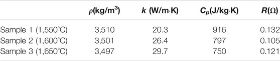
TABLE 1. The physical properties of the β″-Al2O3 prepared with different sintered temperatures (measured at 15°C).
In order to explore the microstructure of the solid β"-Al2O3 (the material of NaK-BASE tube), the samples obtained by the method above are scanned by the SEM (Ultra55, Germany), and the microstructures of the samples are all consisted of many convex polygons, and the SEM photos are shown in Figure 1A–C.
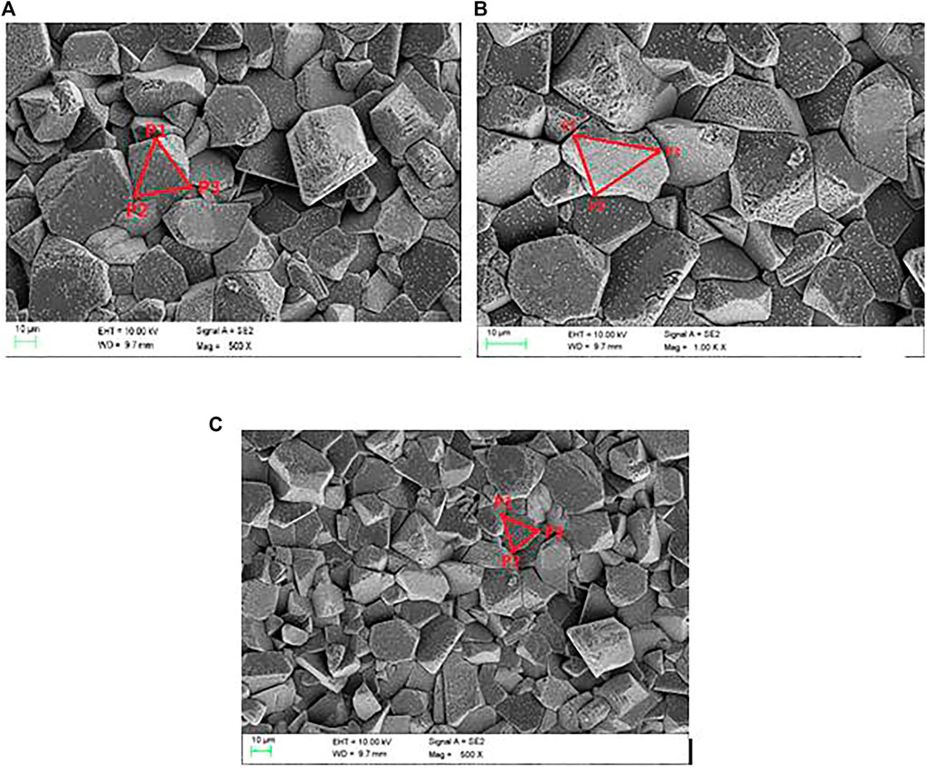
FIGURE 1. the SEM photos of the solid β”-Al2O3 sintered at different temperatures. (A) 1550°C, (B) 1600°C, (C) 1650°C.
The Numerical Simulation of the Heat Transport in the BASE Tube
In the operating process of the NaK-AMTEC, the transport of Na+ and K+ is not only affected by the electric field in the base tube, but also by the temperature field, and thus the heat transport should be considered in the investigation on the transport of Na+ and K+ in NaK-BASE tube.
Although the PNP model with two cations, multiple solutions could exist in NaK-BASE tube, however, the present research focus on the effect of sintered temperature on the heat and cation transport, the PNP model are assumed to single cation model. The double cations and the triple cations model will be investigated in the future work. In order to simplify the numerical simulation, several assumptions are used to simulate the heat transport of the NaK-BASE tube:
1 Two dimensional heat transport;
2 The wall connecting to the heat source keeps constant temperature;
3 The radiation inside the NaK-BASE tube is ignored;
4 The PNP model are all single cation model.
In Figure 1, the microstructure of the NaK-BASE shows apparent fractal characteristics. According to the conclusions of Adler and Thovert (1993), the thermal conductivity in solid with microstructures with apparent fractal characteristics still complies the Fourier’s Law, therefore, the 2-D numerical transient thermal conductivity differential equations are employed to describe the heat transport in NaK-BASE tubes:
where T is the temperature of the NaK-BASE, K; k is the thermal conductivity of the NAK-BASE tube, W/(m·K).
However, the thermal conductivity coefficient of the NaK-BASE tube is not a fixed value but rather related to the fractal characteristics of the microstructures. As mentioned above, the microstructures of the NaK-BASE show apparent fractal characteristics and thus there are many micro/nano cavities inside the NaK-BASE, as a result, the heat conductivity transforms not only among the solid particles, but also transforms through the air inside the micro/nano cavities. Therefore, the thermal conductivity of the NaK-BASE tube is decided by the fractal characteristics. In present research, the solid samples of NaK-BASE tube is obtained by sintering the cuboids pressed by the precursor powder at high pressure, and according to Qin et al. (2008), the dimensionless effective thermal conductivity of solid obtained by this method can be calculated by Eq. 2 if the fractal characteristics is apparent in the solid and the radiation inside the NaK-BASE tube can be neglected:
where, ke+ is the dimensionless effective thermal conductivity of the solid; kg is the thermal conductivity of the air, W/(m•K); ks is the thermal conductivity of the solid, W/(m•K); Df is the fractal dimension of the NaK-BASE tube.
The dimensionless effective thermal conductivity of NaK-BASE tube is defined as the following equation:
where ke is the effective thermal conductivity of the NaK-BASE tube.
The fractal dimension of the NaK-BASE tube that can be calculated by the equation below (Sun et al., 2010):
where ρ is the stacking density of the powder, kg/m3; ρs is the density of the particles, kg/m3; ρg is the density of air, kg/m3; Dmin and Dmax is the minimal and maximal diameter of the solid particle, respectively, m.
According to the simplifying assumptions, the boundary condition of the wall connecting to the heat source is simplified to constant temperature, and the heat transfer coefficients on the other walls are constant.
The boundary condition at t = 0s on the wall connecting to the heat source:
In Eq. 5, Th refers to the temperature of the heat source of the NaK-BASE, K.
The boundary conditions on the other walls:
In Eq.6, h is the convective heat transfer coefficient, W/(m2·K); Tw is the temperature of the wall, K; Ta is the temperature of the air, K; k is the thermal conductivity of the NAK-BASE tube, W/(m·K);
The additional source term method is utilized to discretize both boundary conditions in Eq. 6.
The values of parameters used in equations above are listed in Table 2.

TABLE 2. The values of the parameters.
The numerical model is calculated by the software ANSYS FLUENT 16.0.
The temperature fields of the NaK-BASE tube sintered at temperature of 1550°C (the precursor powder is sintered at temperature of (1,350°C)) are predicted by Eqs. 1–4 when the operating temperature is 800, 900, 1000 and 1100 K, respectively, and the results are shown in Figure 2A–D.
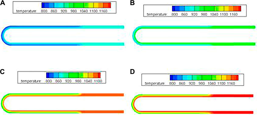
FIGURE 2. Temperature fields inside the NaK-BASE tube (sintered at temperature of 1550°C) at different operating temperatures (t=360 s). (A) 800 K, (B) 900 K, (C) 1000 K, (D) 1100 K.
In Figure 2A–D, the temperature of the heat source affects the temperature fields inside the NaK-BASE tube apparently. Except for the sealed part of the NaK-BASE tube, the temperature gradient increases apparently with the increase of the heat source temperature inside the part of NaK-BASE tube working together with electrodes of the metal films. The maximal temperature difference inside the NaK-BASE tube increases from 100 to 150 K when the heat source temperature increasing from 800 to 1100 K, as shown in Figure 2.
The comparisons among the temperature distributions in NaK-BASE tube with different sintered temperatures are shown in Figure 3A–D. It can be seen that the heat transfer is related to the sintered temperature of the NaK-BASE, and the average temperature difference inside the NaK-BASE becomes high with the increase of the sintered temperature at the same heat source temperature, as shown in Figure 3A–D.

FIGURE 3. The temperature fields of different NaK-BASE tubes in Table 1 at temperature of 900 K (t = 360 s). (A) Sample1 in Table 1, (B) Sample2 in Table 1, (C) Sample3 in Table 1.
In order to investigate the effect of microstructure on the temperature distribution in the NaK-BASE tube, the average temperatures on the five cross section surfaces of the NaK-BASE tubes are illustrated in Figure 4 with the heat source temperature of 800 K, and NaK-BASE tubes are made of the four types materials in Table 1. The locations of the cross section surfaces are shown in Figure 5, which are named as Plane1, Plane2, Plane3, Plane4 and Plane5, respectively. It can be known that the average temperatures all become high with the increase of the sintered temperature on different cross sections of the NaK-BASE.
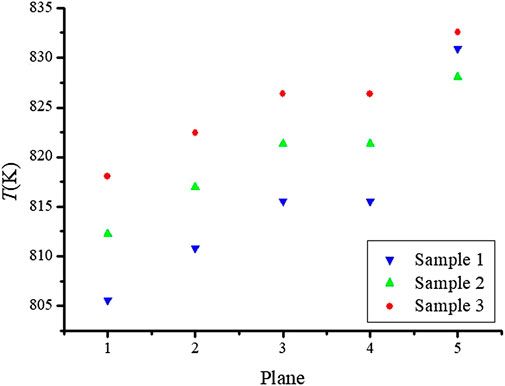
FIGURE 4. Schematic of the cross section surfaces.
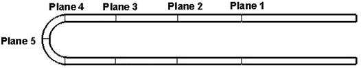
FIGURE 5. The average temperatures on the cross section surfaces of the four. NaK-BASE tubes made of the materials in Table 1 (with heat source temperature of 800 K, t = 360 s).
Above all, the temperature distribution of the NaK-BASE tube is related to the microstructure directly. Due to the effect of the temperature distribution on the transport of Na+ and K+ in the NaK-BASE, the influence of the microstructure of NaK-BASE on the transport of Na+ and K+ should be investigated when the NaK-BASE tubes are made of different materials sintered at different temperatures.
The Fractal Grid and the Numerical Simulation on the Transport of Na+ and K+
As shown in Figures 1A–C, the microstructures of the different NaK-BASE are all consisted of many convex polygons. In order to generate grid to simulate the microstructures, the fractal dimensions of the samples in Table 1 are calculated by Eq. 4 and the results are 2.79, 2.76 and 2.73, respectively. So the microstructure of the NaK-BASE material show fractal characteristics and thus the Voronoi diagram generation algorithm can be employed to construct the microstructure of NaK-BASE in present research.
In the generation of the Voronoi diagram, the number of the polygons N is decided by taking the square root of total number of the particles per unit area, which is equal to the number of original vortex. The number of original vortex is N = 83, 85 and 88 in the microstructures in Figures 1A–C, respectively. Since the Delaunay triangulation is the dual diagram of the Voronoi diagram, the Delaunay triangulation grid is generated by the incremental insertion. In the generation of the Delaunay triangulation, the ConvexHull is generated by incremental method, and initial ConvexHull List (P1, P2, P3) are picked based on structural characteristics according to the SEM photos, respectively, as shown in Figures 1A–C, and then the Delaunay triangulation can be generated by point insertion algorithm. The generated Voronoi diagrams of the different NaK-BASE material are shown in Figures 6A–C, which can describe the fractal characteristics of the materials as shown in Figure 1A–C.
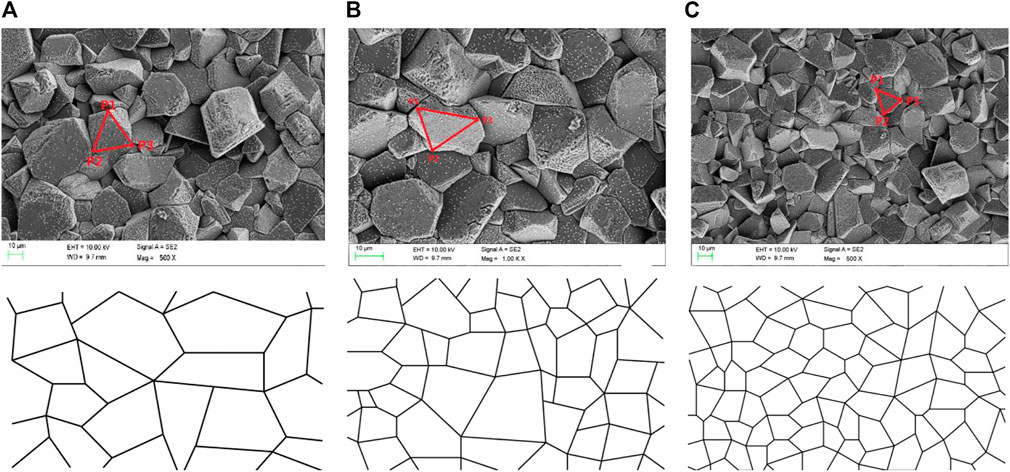
FIGURE 6. (A) Voronoi diagram of sample1 in Table 1, (B) Voronoi diagram of sample2 in Table 1, (C) Voronoi diagram of sample3 in Table 1.
The transport of ions can be described by Fick’s law when the ions pass through the pores without electric charge (Li et al., 2011):
where j is the diffusive flux of ions in NaK-BASE, kg/s.
The volume average of Eq. 5 can be written as the following equation:
In Eq. 8, τ is the tortuosity coefficient of NaK-BASE;
According to the Fick’s law, the diffusion of the ions in solid with porous structure is only related to the concentration gradient, and cannot be affected by the ion type, quantity of charge and pores. Besides, the transport of the ions is also affected by the interactions among the ions with different diffusive velocity and the solid particles with electric charge inside the NaK-BASE. Therefore, the transport of the cation can be described by the Nernst-Planck equation when the cations pass through the NaK-BASE tube (Samson and Marchand, 1999).
where ji is the flow flux of the No.i cation; Di is the diffusion coefficient; ci is the concentration of the No.i cation; zi is the charge number of the No.i cation; F is the Faraday Constant; R is the gas constant; T is the temperature of the NaK-BASE, K; ∇ci is the concentration gradient of the No.i cation; ∇φ is the potential gradient of No.i cation.
The change of the space potential charge can be described by Poission equation as followed:
where ε is the dielectric constant of NaK-BASE, F/m; εa is the relative dielectric constant of the air; Cs is the surface charge density of particle, C/m2.
In the continuum approach, ions are treated as Brownian particles, the dynamics of which is described by the Smoluchowski equation (Koumanov et al., 2003):
In steady state, the following equation can be concluded:
Eq. 12 can be discreted by the finite difference method. For any internal point k, the finite difference representation of Eq. 12 gives:
In Eq. 14, the subscript and superscript indexes designate the ion species and the grid points. The summations are over the six grid points neighboring point k.
The potential of the cation can be expressed in FD terms as:
The FD formula for the potential
The factor
The concentrations of the cations in NaK-BASE are calculated based on Eqs. 14–16 by the program written in C++ language.
The values of parameters used in equations above are listed in Table 3.
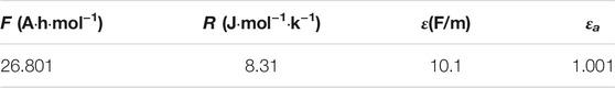
TABLE 3. The values of the parameters.
The boundary conditions on the walls connected to the film electrode:
The boundary conditions on the other walls:
The symmetry boundary conditions of Eq. 18 are solved by additional source term method.
In order to validate the numerical model in present research, the results predicted by present model are compared with the results of Li (Li et al., 2011). Li et al. (2011) investigated the multi-ions transport in porous media, and obtained the relationship between the tortuosity and the ion concentration. In present research, the relationship between the tortuosity and the ion concentration are numerically predicted by the present model and compared with the results of Li (Li et al., 2011), as shown in Figure 7. It can be known form Figure 7 that the results of present research are smaller than the results of Li (Li et al., 2011), and the discrepancies are all within 6.5%. The discrepancy between the present numerical model and the results of Li (Adler and Thovert, 1993) may attributed to the difference of the Voronoi diagram that is constructed based on the SEM photos in present research.
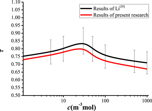
FIGURE 7. The relationship between the tortuosity and the ion concentration obtained by present model and Li (Adler and Thovert, 1993).
According to the temperature distribution in Figures 2, 3, the temperature of NaK-BASE is in the range of 800–1,200 K when the temperature of heat source changes from 900 to 1,200 K. Therefore, the relationships among tortuosity coefficient, concentration of cations and surface charge density of particle are investigated when the heat source temperature in NaK-BASE is 800 K, 900 K, 1,000 K and 1,100 K, respectively, to analyze the effect of temperature on the transport characteristics of Na+ and K+ in the NaK-BASE tube.
Figure 8 and Figure 9 shows the relationships of cation concentration with the tortuosity of the NaK-BASE. It can be known from Figure 8 that the cation concentration increases at first and then decreases with the increase of the tortuosity of NaK-BASE with different surface charge density, and the peak of the cation concentration appears in the range of Cs = 0.89–0.9, and the peak value of the cation concentration reaches 180 mol/m3. In addition, there is no apparent change of the cation concentration with the increase of surface charge density when the tortuosity of NaK-BASE is small, as shown in Figure 8. However, the peak value of the cation concentration increases with the decrease of the surface charge density.
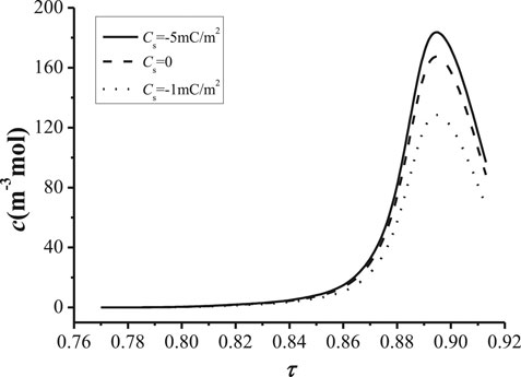
FIGURE 8. Relationship between the cation concentration and the tortuosity.
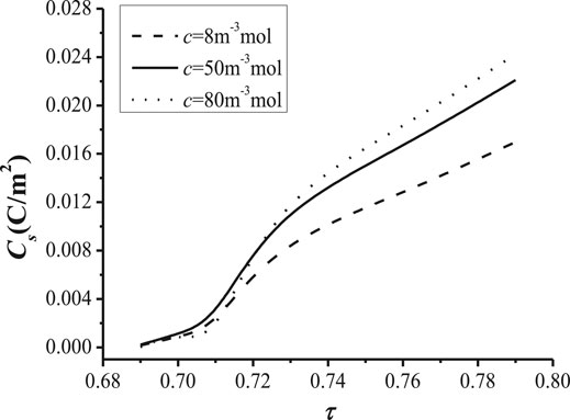
FIGURE 9. Relationship between the surface charge density and. with different surface charge density (T = 800 K, t = 360 s) and the tortuosity with different cation concentration (T = 800 K, t = 360 s).
The change of surface charge density with the increase of the tortuosity of the NaK-BASE is illustrated In Figure 9. It can be found from Figure 9 that the surface charge density becomes high with the increase of the tortuosity at the same cation concentration in the NaK-BASE, and the surface charge density increases linearly with the increase of the tortuosity. Besides, the difference of the surface charge density increases with the increase of the tortuosity among the NaK-BASE with different cation concentrations. Consequently, the increase of the cation concentration can improve the surface charge density in the NaK-BASE.
In order to investigate the impact of temperature on the transport of the cation density, the relationship between the cation concentration and the tortuosity with different temperatures is shown in Figure 10, and the relationship between the surface charge density and the tortuosity with different temperatures is shown in Figure 11.
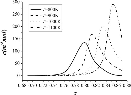
FIGURE 10. The relationship between the cation concentration and.
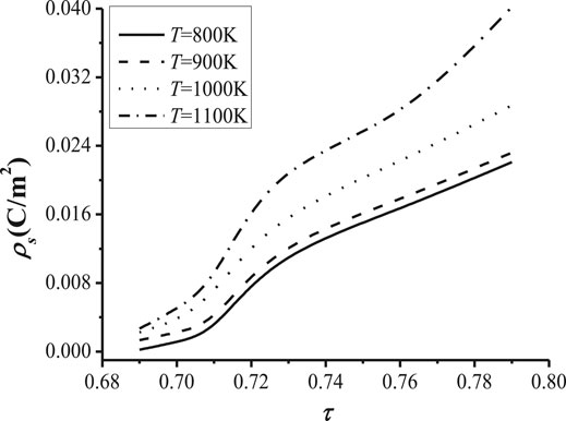
FIGURE 11. The relationship between the surface charge density. the tortuosity with different temperatures (ρs = 1 mC/m2, t = 360 s) and the tortuosity with different temperatures (c = 8 m−3mol, t = 360 s).
In Figure 10, it is illustrated that the cation concentration decreases with the increase of the temperature before the concentration reaches the maximal value in the NaK-BASE with the same tortuosity. However, the maximal value of the cation concentration increases with the increase of the temperature, and the tortuosity with the maximal cation concentration also increases with the temperature, as shown in Figure 10. It can be concluded that the tortuosity of the NaK-BASE should be chosen appropriately according to the temperature of the heat source. In addition, the maximal value of cation concentration is related to the tortuosity of the NaK-BASE, which is decided by the heat source temperature, and the maximal value of cation concentration reaches from 140 mol/m3 to 290 mol/m3.
Figure 11 illustrates the change of the surface charge density with the tortuosity of the NaK-BASE at heat source temperatures of 800 K, 900 K, 1000 K and 1100 K. It can be seen from Figure 11 that the surface charge density becomes high with the increase of the heat source temperature in NaK-BASE, and the discrepancy of surface charge density increases with the increase of the tortuosity in NaK-BASE with different heat source temperature, as shown in Figure 11. Therefore, the performance of the NaK-AMTEC can be improved by increasing the heat source temperature of the NaK-BASE due to the increase of the cation concentration and the surface charge density of NaK-BASE. Combined with the temperature distributions of NaK-BASE tubes in Figure 2, it can be concluded that the micro structure of the NaK-BASE samples prepared at temperature of 1,600°C and 1,650°C can improve the performance of the NaK-AMTEC in present research.
Conclusions
1 The heat transport in NaK-BASE is affected by the sintered temperature apparently, and the temperature difference in the NaK-BASE increases with the increase of the sintered temperature.
2 The average temperature of the NaK-BASE becomes high with the increase of the sintered temperature with the same heat source temperature.
3 The cation concentration increases at first and then decreases with the increase of the tortuosity of NaK-BASE with different surface charge density, and the peak of the cation concentration appears in the range of Cs = 0.89–0.9, and the peak value of the cation concentration reaches 180 mol/m3;
4 The maximal value of cation concentration is related to the tortuosity of the NaK-BASE, which is decided by the heat source temperature, and the maximal value of cation concentration reaches from 140 mol/m3 to 290 mol/m3.The cation concentration can be coordinated by changing the tortuosity of the NaK-BASE.
5 The surface charge density increases with the increase of the temperature in the NaK-BASE, and the discrepancy of the surface charge density increases with the increase of the tortuosity.
Data Availability Statement
The raw data supporting the conclusions of this article will be made available by the authors, without undue reservation.
Author Contributions
All authors listed have made a substantial, direct, and intellectual contribution to the work and approved it for publication. NG completed the numerical investigation and WC carried out the experimental research. The manuscript was revised by YG.
Funding
National Natural Science Foundation of China (U1833121); Natural Science Foundation of Shandong Province (ZR2020MA061); Shandong Province Higher Educational Youth Innovation Science and Technology Program (2019KJJ009); China Postdoctoral Science Foundation (2020M671983); Shandong Provincial Housing Urban and Rural Construction Science and Technology Project (2020-K2-10); and the Plan of Guidance and Cultivation for Young Innovative Talents of Shandong Provincial Colleges and Universities.
Conflict of Interest
The authors declare that the research was conducted in the absence of any commercial or financial relationships that could be construed as a potential conflict of interest.
Publisher’s Note
All claims expressed in this article are solely those of the authors and do not necessarily represent those of their affiliated organizations, or those of the publisher, the editors and the reviewers. Any product that may be evaluated in this article, or claim that may be made by its manufacturer, is not guaranteed or endorsed by the publisher.
References
Adler, P. M., and Thovert, J.-F. (1993). Fractal Porous media. Transp Porous Med. 13 (1), 41–78. doi:10.1007/bf00613270
Chen, K. G., Xu, X., and Lin, Z. (1997). Preparation of Na-Β”-Al2O3 Ceramics by Reaction Sintering Method [J]. J. Inorg. Mater. 12 (4), 521–524.
Diez de los Rios Ramos, N., Hering, W., Weisenburger, A., Stüber, M., Onea, A., Lux, M., et al. (2017). Design and Construction of the ATEFA Facility for Experimental Investigations of AMTEC Test Modules. IOP Conf. Ser. Mater. Sci. Eng. 228 (1), 012014. doi:10.1088/1757-899x/228/1/012014
El-Genk, M. S., and Tournier, J.-M. P. (2004). "SAIRS" - Scalable Amtec Integrated Reactor Space Power System. Prog. Nucl. Energ. 45 (1), 25–69. doi:10.1016/j.pnucene.2004.08.002
Kim, S. D., Kim, H. T., Seo, D. W., Kim, S. Y., Suh, M-S., and Woo, S-K. (2014). Novel Mo/TiN Composites for an Alkali Metal Thermal-to-Electric Converter (AMTEC) Electrode [J]. Ceramics Int. 40 (9A), 14247–14252. doi:10.1016/j.ceramint.2014.06.014
Koumanov, A., Zachariae, U., Engelhardt, H., and Karshikoff, A. (2003). Improved 3D Continuum Calculations of Ion Flux through Membrane Channels. Eur. Biophys. J. 32 (8), 689–702. doi:10.1007/s00249-003-0330-y
Lee, K. B., Rhi, S. H., Lee, K. W., Lee, W. H., Jang, C. C., Lee, W. G., et al. (2012). Thermal and Flow Modeling of Alkali-Metal Thermoelectric Power Generation (AMTEC). Adv. Mater. Res. 538-541, 419–422. doi:10.4028/www.scientific.net/amr.538-541.419
Lee, K.-W., Lee, W.-H., Rhi, S.-H., and Lee, K.-B. (2012). Analysis of Pressure Drop and Heat Loss in Liquid Sodium Circulation Wick of AMTEC. Trans. Korean Soc. Mech. Eng. B 36 (9), 953–960. doi:10.3795/ksme-b.2012.36.9.953
Li, R. M., Liu, S. Y., Fang, F., Zhang, L. L., Suo, J. P., and Liu, S. M. (2011). Tortuosity Analysis of Porous Media Based on Micro-Scale PNP Multi-Ions Transport Model [J]. J. Southeast Univ. (Natural Sci. Edition) 41 (3), 647–651.
Lodhi, M. A. K., and Briggs, J. B. (2007). Temperature Effect on Lifetimes of AMTEC Electrodes. J. Power Sourc. 168 (2), 537–545. doi:10.1016/j.jpowsour.2007.02.086
Mukunoki, H., Fukumasa, O., and Sakiyama, S. (2002). Integrated Synthesis of AMTEC Electrode by Using Controlled Thermal Plasma Processing [J]. Thin Solid Films 407 (1/2), 92–97. doi:10.1016/s0040-6090(02)00018-4
Qin, X. Y., Gu, C. L., Cui, C. H., and Zheng, Z-S. (2008). The Fractal Dimension and the Fractal Model of Thermal Conductivity in Powder Dispersion’s Space of High Velocity Compaction [J]. J. Hubei Univ. Nationalities (Natural Sci. Edition) 26 (2), 131–134. doi:10.3969/j.issn.1008-8423.2008.02.005
Samson, E., and Marchand, J. (1999). Numerical Solution of the Extended Nernst-Planck Model. J. Colloid Interf. Sci. 215 (1), 1–8. doi:10.1006/jcis.1999.6145
Sun, J.-Z., Hu, Y., and Ma, Y.-Q. (2010). Voronoi Diagram Generation Algorithm Based on Delaunay Triangulation. J. Comput. Appl. 30 (1), 75–77. doi:10.3724/sp.j.1087.2010.00075
Tanaka, K. (2010). Concept Design of Solar Thermal Receiver Using Alkali Metal Thermal to Electric Converter (AMTEC) [J]. Curr. Appl. Phys. 10 (2), S254–S256. doi:10.1016/j.cap.2009.07.031
Tong, J. Z., and Ni, Q. Y. (1993). A Unique Direct Energy Conversion Device-Alkali Metal Thermoelectric Converter [J]. Adv. Technol. Electr. Eng. Energ. 12 (1), 19–25.
Wu, S.-Y., Xiao, L., Cao, Y., and Li, Y.-R. (2010). A Parabolic Dish/AMTEC Solar Thermal Power System and its Performance Evaluation. Appl. Energ. 87, 452–462. doi:10.1016/j.apenergy.2009.08.041
Wu, S.-Y., Zhang, Y.-C., Yang, H., and Xiao, L. (2017). Performance Evaluation and Parametric Analysis of AMTEC/TEG Hybrid System. Energ. Convers. Manage. 154, 118–126. doi:10.1016/j.enconman.2017.10.046
Wu, S.-Y., Guo, G., Xiao, L., and Chen, Z.-L. (2019). A New AMTEC/TAR Hybrid System for Power and Cooling Cogeneration. Energ. Convers. Manage. 180, 206–217. doi:10.1016/j.enconman.2018.10.077
Xiao, L., Wu, H. Y., Wu, S. Y., and Chu, Q-W. (2016). “Parametric Analysis of Condensation Heat Transfer Characteristics of AMTEC Wick Condenser [C],” in The 8th International Conference on Applied Energy – ICAE, Beijing, China.
Yuan, Y., Shan, J., Zhang, B., Gou, J., Zhang, B., Lu, T., et al. (2016). Study on Startup Characteristics of Heat Pipe Cooled and AMTEC Conversion Space Reactor System. Prog. Nucl. Energ. 86, 18–30. doi:10.1016/j.pnucene.2015.10.002
Yuan, Y., Shan, J., Zhang, B., Gou, J., Bo, Z., Lu, T., et al. (2016). Accident Analysis of Heat Pipe Cooled and AMTEC Conversion Space Reactor System. Ann. Nucl. Energ. 94, 706–715. doi:10.1016/j.anucene.2016.04.017
Zhang, L. L., Suo, J. P., Liu, S. M., and Ye, C. (2007). Synthesis of Beta-Alumina Powder by Microwave Sintering Assisting Sol-Gel Technique [J]. Bull. Chin. Ceram. Soc. 26 (1), 63–67. doi:10.16552/j.cnki.issn1001-1625.2007.01.014
Zhang, X. (2015). Research on Key Technologies of Small Natural-Circulation Fast Reactor Integrated with AMTEC [D]. Beijing, China: North China Electric Power University.
Zhu, C. F., Xue, J. H., Wang, L., and Wang, X. J. (2010). Synthesis of Beta-Al2O3 Solid Electrolytes by the EDTA Complexing Sol-Gel Method [J]. Chin. J. Inorg. Chem. 26 (7), 1165–1170.
Nomenclature
C Surface charge density C/m2 concentration of the cation
Specific heat capacity J/(kg·K)
D fractal dimension of the NaK-BASE tube
F faraday’s constant
h heat transfer coefficient W/(m2·K)
R gas constant J/(mol·K)
electrical resistivity Ω
T temperature K
u velocity along x direction m/s
v velocity along y direction m/s
x x-coordinate
y y-coordinate
z quantity of electric charge
k thermal conductivity W/(m·K)
Greek letters
Ε dielectric constant
λ diameter of the solid particle m
Φ potential of the cation V/m
τ the tortuosity coefficient
ρ Density kg/m3
Subscript
a Air
e Efficient
f fractal dimension
g Gas
i No.i
p pressure
s solid; surface
w wall
Keywords: thermoelectric converter, temperature, cation concentration, alkali metal, surface charge density
Citation: Guan N, Chen W and Gao Y (2021) Impact of Sintered Temperature on the Heat and Cation Transport in NaK-BASE Tube. Front. Energy Res. 9:741951. doi: 10.3389/fenrg.2021.741951
Received: 21 July 2021; Accepted: 03 September 2021;
Published: 30 September 2021.
Edited by:
Muhammad Wakil Shahzad, Northumbria University, United KingdomReviewed by:
Willy Villasmil, Lucerne University of Applied Sciences and Arts, SwitzerlandMingji Zhang, New Mexico Institute of Mining and Technology, United States
Copyright © 2021 Guan, Chen and Gao. This is an open-access article distributed under the terms of the Creative Commons Attribution License (CC BY). The use, distribution or reproduction in other forums is permitted, provided the original author(s) and the copyright owner(s) are credited and that the original publication in this journal is cited, in accordance with accepted academic practice. No use, distribution or reproduction is permitted which does not comply with these terms.
*Correspondence: Yan Gao, Z2FveWFuLnNkdUBob3RtYWlsLmNvbQ==