- 1Environmental Molecular Sciences Laboratory, Pacific Northwest National Laboratory, Richland, WA, USA
- 2Energy and Environment Directorate, Pacific Northwest National Laboratory, Richland, WA, USA
Lithium-and-manganese-rich (LMR) cathode materials have been regarded as very promising for lithium (Li)-ion battery applications. However, their practical application is still limited by several barriers such as their limited electrochemical stability and rate capability. In this work, we present recent progress on the understanding of structural and compositional evolution of LMR cathode materials, with an emphasis being placed on the correlation between structural/chemical evolution and electrochemical properties. In particular, using Li[Li0.2Ni0.2Mn0.6]O2 as a typical example, we clearly illustrate the structural characteristics of pristine materials and their dependence on the material-processing history, cycling-induced structural degradation/chemical partition, and their correlation with electrochemical performance degradation. The fundamental understanding that resulted from this work may also guide the design and preparation of new cathode materials based on the ternary system of transitional metal oxides.
Introduction
Advanced lithium (Li)-ion batteries with high capacities, high-operating voltages, and high-rate capabilities are required for both portable electronic devices and electric vehicle applications (Chan et al., 2007; Goodenough et al., 2007; Kim et al., 2008; Kang and Ceder, 2009; Park et al., 2009; Sun et al., 2012a, 2009; Wang et al., 2009; Chiang, 2010; Armstrong et al., 2011; McDowell et al., 2011; Yao et al., 2011; Whittingham, 2012). As one of the key components of a Li-ion battery, the cathode is a limiting factor for achieving high-energy densities. Many investigations have focused on the search for advanced cathode materials (Ceder et al., 1998; Tarascon and Armand, 2001; Kang et al., 2006; Sun et al., 2009; Marom et al., 2011; Meng and Arroyo-de Dompablo, 2013; Nam et al., 2013; Lee et al., 2014). Among various candidates, the lithium-and-manganese-rich (LMR) cathode material is regarded as a promising candidate for delivering a much higher energy density than traditional cathode materials such as LiMn2O4 spinel and LiCoO2 (Lu and Dahn, 2002; Kang and Amine, 2005; Yabuuchi et al., 2011; Sun et al., 2012b). For example, the discharge capacity of the typical LMR cathode (Li[Li0.2Ni0.2Mn0.6]O2), which was first developed by Kim et al. (2002) and Thackeray et al. (2005), can exceed 250 mAh g-1 after initial charging (Thackeray, 1999; Johnson et al., 2004; Lee et al., 2006; Lim et al., 2009; Jarvis et al., 2011). In addition, LMR cathode materials have demonstrated good thermal stability, with the onset of thermal decomposition occurring at 250°C (Deng et al., 2009). However, several critical properties of LMR cathodes, including their low-rate capability, voltage fading, and capacity decay during battery cycling, must be improved before they can achieve large-scale market penetration (Choi et al., 2012; Yu and Zhou, 2013; Zheng et al., 2014b, 2013). Moreover, compared with other layered transition metal (TM) oxides, LMR cathodes have poor cyclic stability and short life cycle (Liu et al., 2014; Noh et al., 2014; Zheng et al., 2014b; Nitta et al., 2015). To mitigate the performance degradation, it is crucial to have a better understanding of pristine LMR cathode materials as well as charge–discharge cycling-induced material degradation. In this review, we discuss recent progress in understanding LMR cathode materials, focusing on studies of the structural and chemical characteristics of both pristine, and cycled LMR material using advanced transmission electron microscopy (TEM).
Structural Characteristics of Pristine Material
Pristine LMR cathode materials have a layered structure that can be written as [xLi2MO3× (1-x)LiMO2, 0 < x < 1, M = Mn, Ni, Co, ….]. They are generally believed to be a composite consisting of Li2MO3 and LiMO2 components. The Li2MO3 adopts a monoclinic structure with C2/m symmetry, and the LiMO2 adopts a hexagonal lattice with R-3m symmetry. An ongoing debate about the phase structure of LMR cathode has focused on two questions. Is it a two-phase mixer (monoclinic and hexagonal) structure (Lei et al., 2008; Bareno et al., 2011; Yu et al., 2013), or is it a solid solution of monoclinic structure with C2/m symmetry (Lu et al., 2002; Jarvis et al., 2011)? In fact, both the R-3m hexagonal structure and the C2/m monoclinic structure can be termed as layered structures. As shown in Figure 1, their Li slabs are nearly the same; however, the main structural difference comes from the TM slabs where the TM cations and Li are ordered in a monoclinic structure, while in the hexagonal structure, the TM cations are randomly distributed. The two different structures can show exactly the same projection image when observed from the [010]m and [11–20]h zone axes, respectively. Therefore, to distinguish the two structures, observations from other zone axes are necessary (e.g., the [100]m zone axis and [10–10]h zone axis).
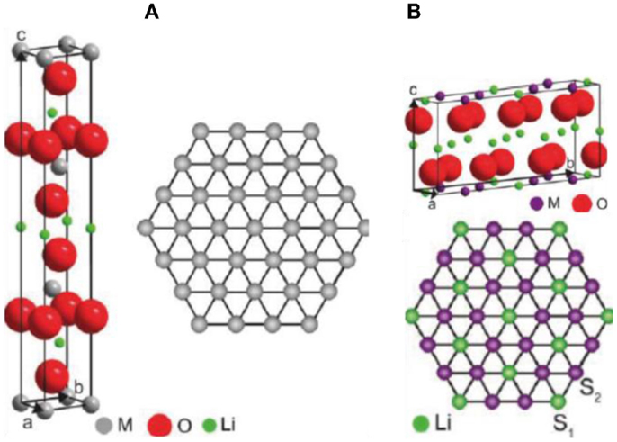
Figure 1. Crystal models for (A) monoclinic and (B) hexagonal structures. Projecting lattice images to show the same and difference between these two structures. Green: Li; Blue: Ni; Purple: Mn; Red: O (Jarvis et al., 2011). Reprinted with permission from Jarvis et al. (2011). Copyright 2011 American Chemical Society.
As one of the most popular LMR cathode materials, Li[Li0.2Ni0.2Mn0.6]O2 (represented by 20N-LMR) can be expressed as (50% Li2MnO3 + 50% LiNi0.5Mn0.5O2). In the literature, the co-precipitation (CP) method has been widely reported for preparing 20N-LMR cathode materials because it is presumed to produce materials with uniform cation distributions (Zheng et al., 2008; Deng et al., 2009; Xu et al., 2011; Yabuuchi et al., 2011). Therefore, nanoscale phase separation in 20N-LMR synthesized by CP may be minimized. However, because of Ni additions, a very high density of plane defects and lamellar domains can be seen in the as-prepared grain bulk. As shown in Figure 2A, areas A, B, and C indicate lamellar domains with different crystal orientations. Stacking fault planes are located between two different domains. Therefore, in the selective area electron diffraction (SAED) patterns, strong streaks can be seen in Figure 2B. In addition to the plane stacking disorder, in-plane disordering also was observed (as marked in Figure 3A). Because a STEM-HAADF image shows the Z-contrast for each atom column, the in-plane disordering indicates that some Li cations have been substituted by heavy TM cations. In Figure 3, a comparison between experimental data and simulation results is shown. The data, which indicate that around 40% (even higher) Li cations in a Li column, have been substituted by TM cations. Therefore, local TM cation aggregation in LMR samples prepared by CP and its influence on the electrochemical performance of the LMR cathode needs to be investigated further.
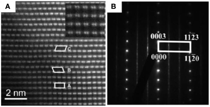
Figure 2. (A) [100]m zone axis STEM-HAADF image of pristine 20N-LMR cathode. Areas marked A, B, and C in (A) correspond to the [100] zone axis, the [1–10] zone axis, and the [110] zone axis, respectively (Jarvis et al., 2011). (B) SAED pattern of pristine 20N-LMR cathode recorded along an [010] zone axis. Continuous narrow streaks along (0001) indicate the presence of several locally monoclinic domains (Bareno et al., 2010). Reprinted with permission from Jarvis et al. (2011) and Bareno et al. (2010). Copyright 2011 American Chemical Society and 2010 John Wiley & Sons, Inc.
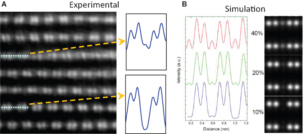
Figure 3. (A) Experimental STEM-HAADF image from [100] zone axis to show local in-plane TM aggregation in the grain bulk. (B) Simulation results to show the changes of STEM-HAADF images with different TM substitutions in the Li column in the TM slab (Gu et al., 2013). Copyright 2013 American Chemical Society.
Nickle Segregation on Particle Surface and Grain Boundary
Selective surface plane segregation of Ni ions was discovered for typical 20N-LMR cathode materials prepared by the CP and sol–gel (SG) methods (Yan et al., 2014; Zheng et al., 2014a), in which the Ni ions preferentially segregated at the surface facets terminated with (200) planes as shown in Figure 4. As evidenced by the bright contrast under STEM-HAADF imaging, the Ni-rich surface layer adopts a different lattice structure as shown in Figure 4B. In Figures 4C–F, X-ray energy dispersive spectroscopy (EDS) mapping revealed the elemental distribution of a pristine 20N-LMR particle, showing that only the (200) facet possesses Ni-segregation while other surface facets do not have a Ni-rich composition (Figure 4D). Figures 4E,F are detailed line scan results. Such pristine Ni-segregation surface (PNS) layer has a typical uniform thickness of ~2 nm. Intensive observations indicate the PNS layer only formed on the (200) surface planes. The high-resolution STEM-HAADF images also indicate some of the Li cations in the Li slabs were substituted by TM cations, which indicate the PNS layer is Li poor.
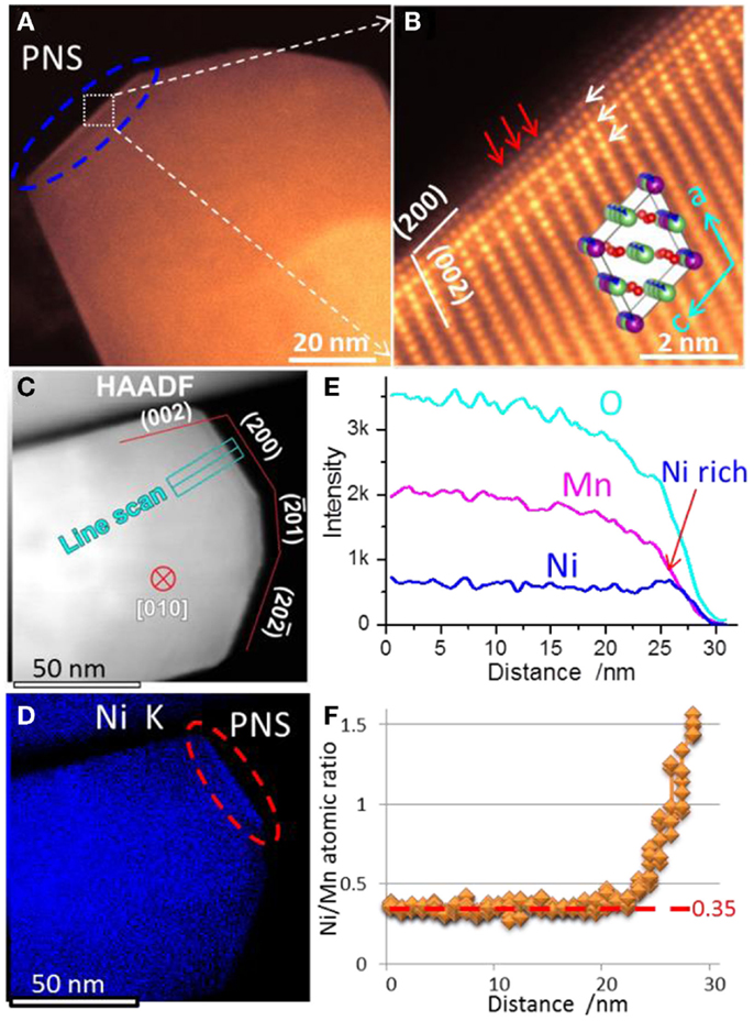
Figure 4. (A) Low magnification and (B) high-resolution STEM-HAADF images of the PNS layer in a pristine particle. White arrows in (B) indicate ordered features along (200) planes. Red arrows in (B) indicated Li slabs being inserted heavy TM cations in the PNS layer. A [010] direction C2/m crystal structure is shown as inset map in (B). (C) STEM-HAADF image of EDS mapping area. The particle was tilted to [010] zone and its surface facets were determined. (D) Corresponding Ni elemental mapping. (E) Line scan signal counts across the PNS layer, whose location is shown in the STEM-HAADF image; (F) Quantitative Ni/Mn atomic ratios along the line scan. The Ni/Mn ratios are around 0.35 in bulk region, which is close to the designed value 0.33 (Yan et al., 2015). Reprinted with permission from Yan et al. (2015). Copyright 2015 American Chemical Society.
In addition to Ni surface segregation, grain-boundary Ni segregation also was observed by three-dimensional EDS mapping. As shown in Figure 5, the EDS results reveal that the Ni/Mn ratio ranges from ~1:4 inside the particle to ~1:1 in certain surfaces and grain boundaries. This unexpected PNS layer and grain-boundary Ni-segregation result in a higher diffusion barrier for Li ions across the particle surface, which consequently leads to poor rate capability and fast capacity fading of LMR cathodes (Meng et al., 2005; Armstrong et al., 2006; Bareño et al., 2010). Therefore, the non-uniform local distribution of TM ions (Ni/Mn) in these materials significantly limited the properties of LMR cathode materials. A uniform Ni/Mn distribution could significantly enhance the electrochemical performance of LMRs.

Figure 5. Z-contrast image of multiple nanoparticle aggregation. (A) EDS maps. (B) Ni map. (C) Overlayed Ni and Mn map. (D) Ni/(Mn + Ni) atomic percentage quantification map. (E) Atomic percentage of Mn and Ni along the white line in (E). [The scale bar in (A) applies to all the images] (Gu et al., 2012a). Reprinted with permission from Gu et al. (2012a). Copyright 2012 American Chemical Society.
Battery Cycling-Induced Structural and Chemical Evolution
Upon cycling, the most discernable change of the 20N-LMR particles is the formation of a surface reconstruction layer (SRL) that also was observed in Ni–Mn-based cathodes (Xu et al., 2011; Boulineau et al., 2013; Lin et al., 2014). It has been generally accepted that cycling-induced SRLs have the following features: (1) formation of oxygen vacancies, (2) TM cations hopping into Li-sites, (3) TM cations being reduced to low valence state, and (4) lattice structure transformation. SAED patterns confirmed the formation of the SRL (as shown in Figures 6A–D), where extra spots are from the newly developed SRL (highlighted by red and blue circles). Figures 6E–J show that TM cations have occupied the octahedral sites in Li slabs within the SRL. With increasing cycle numbers, the thickness of the SRL increases gradually. Moreover, (200) planes were found to be ordered in the SRL and formed double spacing (100) planes, which was further confirmed by high-resolution STEM-HAADF images shown in the inserts of Figures 6I,J. Thus, the SRL structure is actually an ordered structure, which means extra ordering was introduced during cycling as compared with the pristine layered structure. Figure 6J shows a snapshot of the SRL development, where three distinct structures are present from the outmost layer to the inner bulk region. By comparing experimental images with simulation structural models, Yan et al. (2014) proposed that the outmost layers are M3O4-type spinel and the middle transition layer matched best with a tetragonal structure with a space group of I41 (the ICSD No. is 164994).
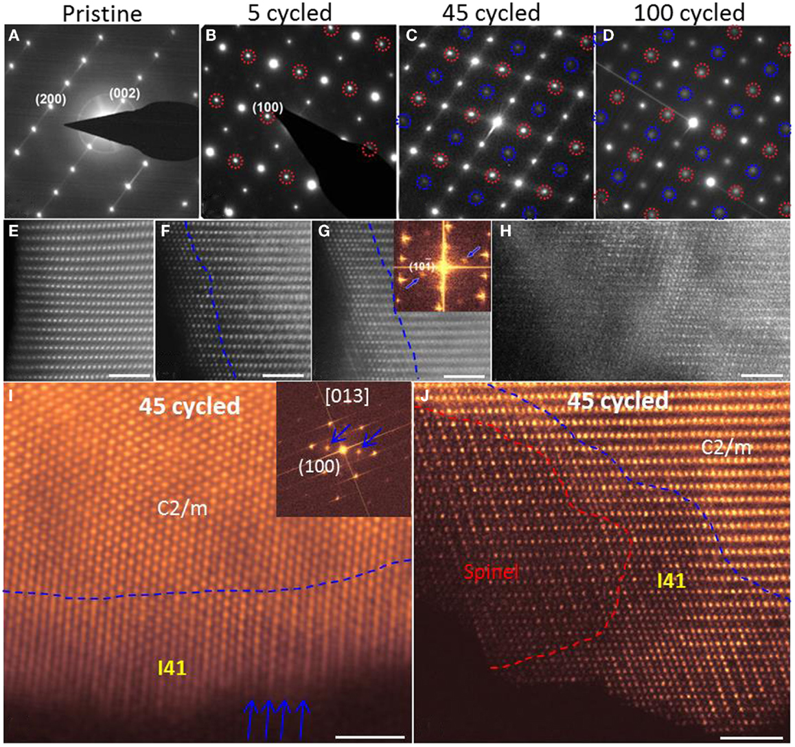
Figure 6. (A–D) [010] zone axis SAED patterns. Extra diffraction spots appeared in cycled samples, which are highlighted by red and blue circles. Red circles indicate the formation of an ordered structure. The (100) ordered plane is clearly seen after cycling. Blue circles come from double diffraction. (E–H) High-resolution STEM-HAADF images that show the cycling-induced structure change on particle surfaces. Pristine samples (E) shows homogeneous structure from surface to bulk. Dashed lines in (F,G) highlight the thickness of the SRL. In (H), whole areas were transformed. (I) [013] zone axis STEM-HAADF image and its fast Fourier transformation image. Blue arrows indicate the ordered features of (200) planes and extra diffraction spots. (J) [010] zone axis STEM-HAADF image to show spinel structure and I41 structure in a sample that was cycled 45 times. The scale bars are 2 nm in (E–J) (Yan et al., 2015). Reprinted with permission from Yan et al. (2015). Copyright 2015 American Chemical Society.
Battery cycling also introduced chemical-composition changes to the particle. As shown in Figure 7, EDS mapping results reveal that the entire surface layer of the 20N-LMR cathode is TM-enriched after 45 cycles. Moreover, the distribution of Mn and Ni within the thin SRL layer also shows spatial partitions; that is, a Ni-poor structure was observed at the outside edge of the SRL (~2 nm in thickness), while a Ni-rich structure was observed at the inner part of the SRL (~6 nm in thickness). Quantitative EDS analysis indicates the Ni/Mn atomic ratio is around 0.26 in the bulk, which is significantly low when compared with a ratio of 0.35 for the pristine material. These observations conclusively indicate that Ni migrates from the bulk region to the surface during cathode cycling, which is consistent with the DFT calculation results that Ni in the Li slab has a relatively low migration barrier when compared with Li (Gu et al., 2012a).
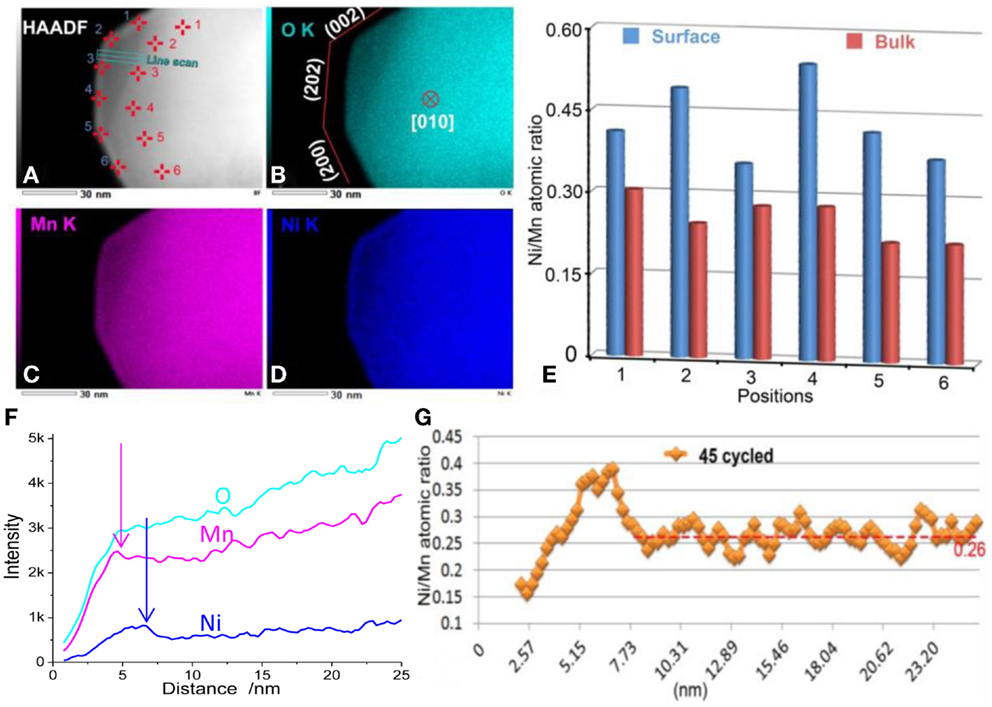
Figure 7. (A–D) EDS mapping results from an LNMO particle cycled 45 times. The particle was tilted to the [010] zone axis and three surface facets were determined in (B). (E) Quantitative Ni/Mn ratios from surface and bulk positions as marked in (A). (F) Line scan signal counts. (G) Quantitative Ni/Mn atomic ratios along the line scan. The Ni/Mn ratios are ~0.26 in the bulk region (Yan et al., 2015). Reprinted with permission from Yan et al. (2015). Copyright 2015 American Chemical Society.
The cycling-induced SRL has three clear differences when compared with the PNS layer. First, the SRL occurred on all surfaces, while the PNS layer only formed on the (200) surface. Second, the outside edge of the SRL is Ni-poor, while the outside edge of the PNS layer has the highest Ni content. Third, the thickness of SRL correlates with cycle numbers and surface facets. It also varies from particle to particle, while the thickness of PNS layer is almost the same for different particles.
Consistent with EDS results, the EELS measurement indicates that the Li content in the SRL gradually decreases, and eventually is depleted with extended cycling. As shown in Figure 8A, the low-loss EELS spectra region contained Mn-M, Li-K, and Ni-M edges. In the sample overcharged to 4.7 V, most of the Li ions have been extracted, showing a depressed Li peak in bulk region. For the pristine sample (PS), a high Li concentration of surface layer (away from PNS) shows a pronounced Li peak. The EELS spectra obtained from the PNS layer of the PS and the cycled samples (45 cycles [45S] and 100 cycles [100S]) exhibit moderate Li peaks, indicating that the Li contents in PNS, 45S, and 100S are lower than that of the PS but higher than the samples charged to 4.7 V. In the core loss region (Figure 8B), both the ratio of Mn L3/L2 and the energy lost position of Mn depends on the cycle numbers, which indicates a valence state change of Mn cations during cycling. By measuring the Mn L3/L2 ratios, the average valence of Mn cations is determined to be <3+ in the SRL, which can introduce large strain from the Jahn–Teller effect and lead to structural destabilization (Ohzuku et al., 1990). Moreover, reduced Mn cations could gain higher mobility and leads to structural changes (Kan et al., 2014).
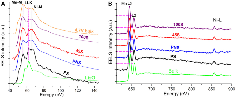
Figure 8. (A) Low-loss EELS spectra and (B) high-loss EELS spectra from different samples. 4.7 V bulk: spectrum collected from the bulk region of the 4.7 V overcharged sample; 100S: spectra collected from the surface of the sample cycled 100 times; 45S: spectra collected from the surface of the sample cycled 45 times; PNS: spectra collected from the Ni-rich surface of PS; PS: spectra collected from the PS surface without a Ni-rich layer; Li2O: spectrum collected from Li2O sample; Bulk: spectrum collected from the bulk region of the PS. The degree of Li-K edge depression is 4.7V bulk > 100S > 45S ≈ PNS > PS. The order of Mn L3:L2 ratio is 100S > 45S > PNS ≈ PS ≈ Bulk (Yan et al., 2015). Reprinted with permission from Yan et al. (2015). Copyright 2015 American Chemical Society.
Combining the EDS and EELS analysis, it is estimated that the composition of the SRL is close to LiM2O3 (M = Mn and Ni). It should be pointed out that the composition varies across the SRL from the outer surface to the inner layer; therefore, an average composition value was chosen to define the SRL composition. Because the SRL thickness increases as the number of cycles increases, the tetragonal I41 structure of the SRL is actually a transition phase. Depending on the Li, TM, and O composition, different phases can be formed. For example, Li2MnO3 adopts a monoclinic C2/m structure; LiMnO2 and Li(Ni0.5Mn0.5)O2 adopt the trigonal R-3m structure; and LiMn2O4 adopts a cubic Fd-3m spinel structure, which could become Mn3O4 spinel with the complete depletion of Li. Therefore, a Li-M-O material should have a very stable structure with a given composition. As evidenced by the EDS and EELS analysis, the cycling-induced SRL exhibits a TM-rich and Li-poor structure, which indicates the formation of SRL involves a progressive TM enrichment and Li depletion upon cycling, and the driving force probably comes from chemical-composition change. As shown in Figure 6J, a Li-depletion M3O4-spinel was developed outside of the I41 structure, which indicates the I41 structure can finally transformed into M3O4-spinel with further depletion of Li content. Thus, a phase transformation sequence for the surface layer is proposed as C2/m → I41 → M3O4-spinel. This conclusion also is supported by Figure 6D in which the outer layer of cycled sample (100S) is shown to exhibit a clearer spinel-featured structure.
Upon continuous cycling of the battery, a progressive TM-enrichment and Li-depletion process is ongoing at the surface of LMR particles, leading to the formation of the SRL. Structurally, in accordance with the chemical-composition change, the SRL went through phase-transition sequences of C2/m → I41 → M3O4-spinel. The schematic diagram in Figure 9 shows the surface layer evolution process upon continuous cycling. On the left side of the figure, a pristine C2/m phase LMR particle with PNS layers on the (200) planes is shown. After cycling, a thin SRL is developed on the particle surface except on the PNS layers (which is formed by Ni migration from the bulk region to the surface, and by Mn2+ cation surface aggregation). In the SRL, the very outside layer eventually becomes Mn-rich and Ni-depleted, and the inner layer becomes Ni-rich. Because of the TM segregation and Li depletion in the SRL, the original C2/m phase loses its layered structure and transforms into a I41 structure. Further cycling finally transforms the outside layer into M3O4-spinel (Yan et al., 2015).
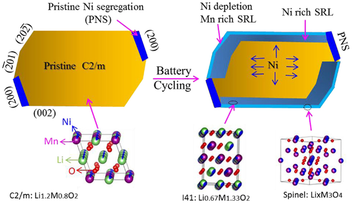
Figure 9. Schematic diagram showing cycling-induced surface layer evolution. At the left side, the pristine particle has a C2/m structure, and PNS layers are located at (200) surface planes. After cycling, because of Ni2+ migration from the bulk region to the surface, Mn2+ surface aggregation and Li+ depletion in surface layer, an SRL is developed on the particle surface, except for the PNS. The surface layer structure transforms from the original C2/m into I41 and finally develops a spinel structure because of progressive TM enrichment and Li depletion. The I41 structure is the main phase in the SRL (Yan et al., 2015). Reprinted with permission from Yan et al. (2015). Copyright 2015 American Chemical Society.
It has been generally accepted that voltage fading and capacity decay are, to some degree, directly correlated with the formation of the SRL on the particle. On the other hand, the SRL may not be the dominating factor for the observed voltage fading and capacity decay of LMR cathodes because the thin SRL is only a small portion of cathode. Observations of the structural features and chemical-composition evolution of the SRL during cycling, and its direct correlation with the compositional change of the bulk lattice, indicate that voltage fading and capacity decay of LMR cathodes are directly correlated to the SRL on the surface of each particle. This conclusion is supported by the following points.
1. Gradual migration of Ni from the bulk lattice to the surface will lead to gradual depletion of Ni from the bulk lattice and directly lead to capacity fading. Furthermore, with decreasing Ni content, the Mn–Ni interaction becomes weaker, thereby resulting in material destabilization (Kim et al., 2013).
2. The SRL is a TM-rich layer in which the Li position in the Li slab is gradually occupied by TM cations following a certain diffusion path way (Breger et al., 2006; Kang et al., 2006; Li et al., 2007). According to a recent simulation by Lee et al. (2014), the SRL forms a barrier for Li migration, therefore contributing to voltage fading.
3. The formation of patches of Li-depleted spinel at the very surface of the particle essentially cut off the Li transport path, making the Li in the particle inaccessible and leading to both voltage and capacity fading.
Mitigating Pristine Ni Segregation and Stabilizing Surface Structure
The formation of a pristine Ni-rich surface layer transformed the local lattice structure, leading to partial substitution of Li ions by Ni ions and blocking of the diffusion path for Li ions. Consequently, such a Ni-rich surface layer contributes to capacity loss and poor rate capability. Suppressing the formation of a Ni-rich surface will lead directly to better cell performance. Zheng et al. (2014a) reported that fabrication of 20N-LMR by a hydrothermal assisted (HA) method yields particles with significantly suppressed Ni segregation on the particle surface as confirmed by STEM EDS analysis. As shown in Figure 10, results from EDS mapping show that the samples prepared by the CP and SG methods exhibit a clear Ni-rich surface layer but the sample prepared by HA method does not have a Ni-rich surface layer. As shown in the electrochemical performance comparison in Figure 11, the HA sample exhibits much better capacity retention, rate capability, and voltage stability. Because of the suppressed phase transformation (less voltage fade) and the excellent structural stability for Li-ion insertion/extraction (stable capacity), the HA material exhibits an energy density of 750 Wh kg−1 and almost no energy fade over 200 cycles (Zheng et al., 2014a).
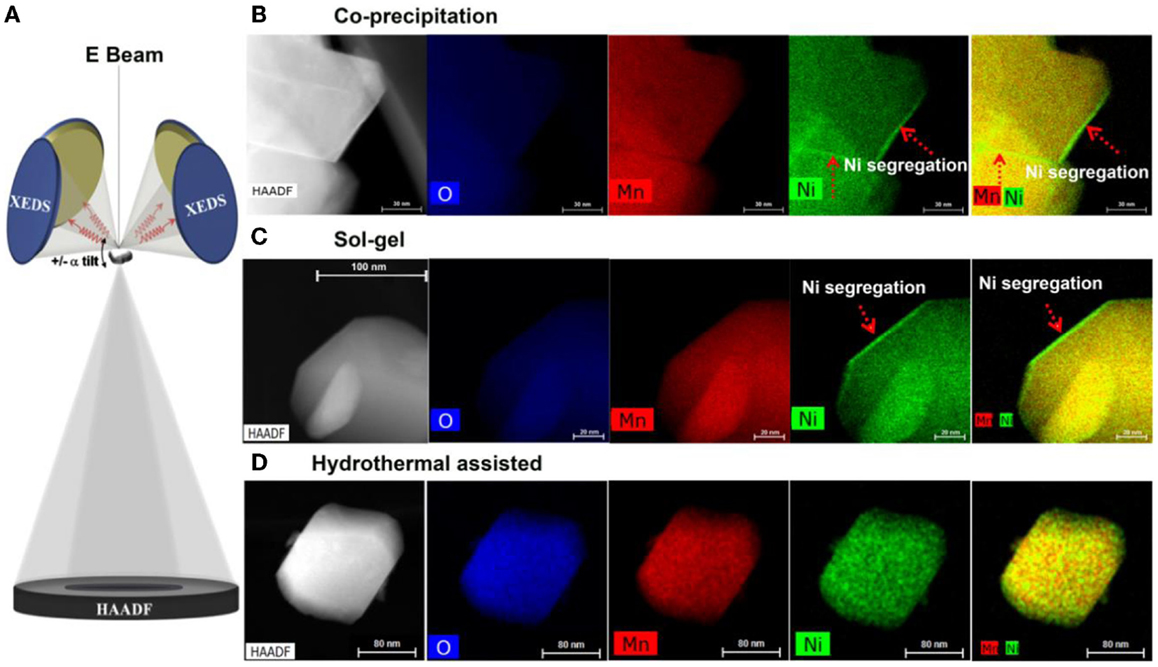
Figure 10. Z-contrast imaging and EDS mapping of materials prepared by different methods. (A) Schematic drawing showing the newly developed four-detector system in a TEM, enabling efficient collecting of the EDS signal. Z-contrast images as well as XEDS maps of Mn, Ni, and overlaid Mn/Ni maps of (B) CP material; (C) SG material; and (D) HA material. CP and SG materials show clear Ni-rich surface layer as indicated by the red arrows. HA sample shows no Ni-rich surface layer (Zheng et al., 2014a). Reprinted with permission from Zheng et al. (2014a). Copyright 2014 American Chemical Society.
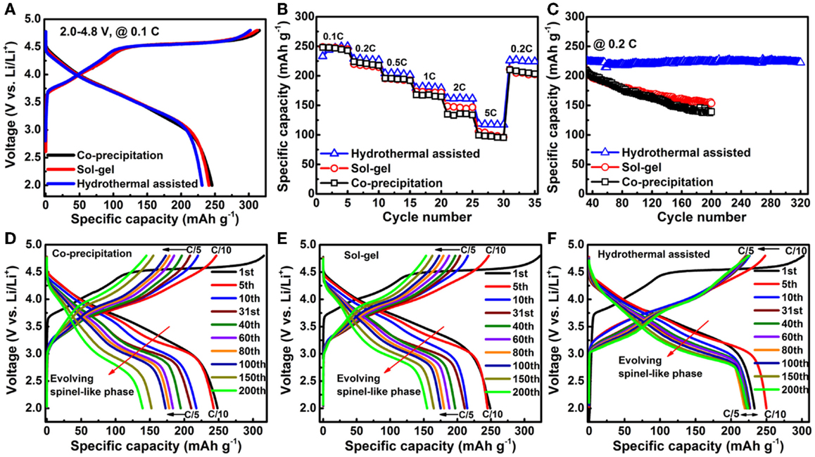
Figure 11. Charge/discharge characteristics of LMR cathodes prepared by different methods. (A) Initial charge/discharge profiles at C/10 in the voltage range of 2.0 ~ 4.8 V; (B) Comparison of rate performance; (C) Cycling performance at C/5 after rate performance tests; Corresponding charge/discharge profile evolutions of materials prepared by the (D) CP; (E) SG; and (F) HA methods during long-term cycling (Zheng et al., 2014a). Reprinted with permission from Zheng et al. (2014a). Copyright 2014 American Chemical Society.
Several literature reports have consistently demonstrated that the structure instability of a surface layer (including phase transformation and corrosion) is directly related to the performance degradation of cathode materials (Xu et al., 2011; Gu et al., 2012b; Zheng et al., 2013). Recently, Yan et al. (2014), observed that different surface facets had different stabilities. As shown in Figures 12A–D, the overall morphological evolution of the particles is shown after different cycle numbers. As cycling preceded, the particle became corroded in the electrolyte, leading to the formation of cracks and pits as shown in Figures 12C,D. Surprisingly, the crystallographic planes, such as (002) and (200), which are composed of pure cations/anions, were found to be relatively stable and show strong resistance against corrosion. Hai et al. (2013) have demonstrated that, for spinel LiMn1.5Ni0.5O4 cathode materials, particle morphology has a dominant effect on Li-ion transport properties, indicating the significant role of surface structure on the stability of the particle in liquid. Li et al. (2014) has shown that NH4F surface modification on an LMR cathode can significantly improve rate capability and cyclability due to the formation of spinel-like surface and F ion doping. Therefore, controlling particle surface facets and additional surface modifications will be promising approaches for further improving the electrochemical performance of LMR cathodes.

Figure 12. (A–D) Low-magnification STEM-HAADF images to show cycling-induced corrosion. Cracks and pits are highlighted by red arrows. (002) surface planes show strong resistance to corrosion. The scale bars are 30 nm (Yan et al., 2015). Reprinted with permission from Yan et al. (2015). Copyright 2015 American Chemical Society.
Conclusion
In this review, we review recent progress in advancing the understanding of LMR cathode materials. For pristine 20N-LMR materials, samples synthesized by the CP and SG methods show a Ni-rich layer on particle surfaces but only on the (200) plane facets, which is detrimental to the electrochemical stability of LMR cathodes. Suppressing Ni segregation significantly enhances electrochemical performance, as seen by the improved cycling stability and mitigated voltage fading in the sample synthesized by the HA method. Systematic TEM investigations on samples with different cycle numbers revealed that the structural degradation of the cathode particle started at the particle surface and propagated into the inner bulk lattice, and was accompanied by a progressive chemical-composition changes. Such structural and chemical changes degrade both the material and cell performance. Optimizing the synthesis method and maximizing the stable surface planes show promise for suppressing such material degradation. These findings advanced our understanding of the LMR cathode and provided promising guidance in ways to mitigate performance degradation. Better understanding the correlation between the structure, especially the surface structure of cathode material, and its electrochemical properties also may provide useful clues for improving the performances of other electrode materials used in rechargeable battery systems.
Conflict of Interest Statement
The authors declare that the research was conducted in the absence of any commercial or financial relationships that could be construed as a potential conflict of interest.
Acknowledgments
This work was supported by the Assistant Secretary for Energy Efficiency and Renewable Energy, Office of Vehicle Technologies, of the U.S. Department of Energy under Contract No. DE-AC02-05CH11231, Subcontract No. 6951379 under the Advanced Battery Materials Research (BMR) Program. The high-spatial-resolution and high-efficiency EDS analysis described in this paper is supported by the Laboratory Directed Research and Development Program as part of the Chemical Imaging Initiative at Pacific Northwest National Laboratory (PNNL) and conducted in the William R. Wiley Environmental Molecular Sciences Laboratory (EMSL), a national scientific user facility sponsored by DOE’s Office of Biological and Environmental Research and located at PNNL. PNNL is operated by Battelle for the Department of Energy under Contract DE-AC05-76RLO1830.
References
Armstrong, A. R., Holzapfel, M., Novák, P., Johnson, C. S., Kang, S.-H., Thackeray, M. M., et al. (2006). Demonstrating oxygen loss and associated structural reorganization in the lithium battery cathode Li[Ni0.2Li0.2Mn0.6]O2. J. Am. Chem. Soc. 128, 8694–8698. doi:10.1021/ja062027
Armstrong, A. R., Lyness, C., Panchmatia, P. M., Islam, M. S., and Bruce, P. G. (2011). The lithium intercalation process in the low-voltage lithium battery anode Li1+xV1-xO2. Nat. Mater. 10, 223–229. doi:10.1038/Nmat2967
Bareno, J., Balasubramanian, M., Kang, S. H., Wen, J. G., Lei, C. H., Pol, S. V., et al. (2011). Long-range and local structure in the layered oxide Li1.2Co0.4Mn0.4O2. Chem. Mater. 23, 2039–2050. doi:10.1021/Cm200250a
Bareno, J., Lei, C. H., Wen, J. G., Kang, S. H., Petrov, I., and Abraham, D. P. (2010). Local structure of layered oxide electrode materials for lithium-ion batteries. Adv. Mater. 22, 1122–1127. doi:10.1002/adma.200904247
Bareño, J., Lei, C. H., Wen, J. G., Kang, S. H., Petrov, I., and Abraham, D. P. (2010). Local structure of layered oxide electrode materials for lithium-ion batteries. Adv. Mater. 22, 1122–1127. doi:10.1002/adma.200904247
Boulineau, A., Simonin, L., Colin, J. F., Bourbon, C., and Patoux, S. (2013). First evidence of manganese-nickel segregation and densification upon cycling in Li-rich layered oxides for lithium batteries. Nano Lett. 13, 3857–3863. doi:10.1021/nl4019275
Breger, J., Meng, Y. S., Hinuma, Y., Kumar, S., Kang, K., Shao-Horn, Y., et al. (2006). Effect of high voltage on the structure and electrochemistry of LiNi0.5Mn0.5O2: a joint experimental and theoretical study. Chem. Mater. 18, 4768–4781. doi:10.1021/Cm060886r
Ceder, G., Chiang, Y. M., Sadoway, D. R., Aydinol, M. K., Jang, Y. I., and Huang, B. (1998). Identification of cathode materials for lithium batteries guided by first-principles calculations. Nature 392, 694–696. doi:10.1038/33647
Chan, C. K., Zhang, X. F., and Cui, Y. (2007). High capacity Li ion battery anodes using Ge nanowires. Nano Lett. 8, 307–309. doi:10.1021/nl0727157
Chiang, Y. M. (2010). Materials science. Building a better battery. Science 330, 1485–1486. doi:10.1126/science.1198591
Choi, N.-S., Chen, Z., Freunberger, S. A., Ji, X., Sun, Y.-K., Amine, K., et al. (2012). Challenges facing lithium batteries and electrical double-layer capacitors. Angew. Chem. Int. Ed. 51, 9994–10024. doi:10.1002/anie.201201429
Deng, H., Belharouak, I., Sun, Y.-K., and Amine, K. (2009). LixNi0.25Mn0.75Oy (0.5 ≤x ≤2, 2 ≤y ≤2.75) compounds for high-energy lithium-ion batteries. J. Mater. Chem. 19, 4510–4516. doi:10.1039/B904098F
Goodenough, J. B., Abruña, H. D., Buchanan, M. V., Visco, S., Whittingham, M. S., Dunn, B., et al. (2007). Report of the Basic Energy Sciences Workshop on Electrical Energy Storage. Available at: http://web.anl.gov/energy-storage-science/publications/EES_rpt.pdf
Gu, M., Belharouak, I., Genc, A., Wang, Z., Wang, D., Amine, K., et al. (2012a). Conflicting roles of nickel in controlling cathode performance in lithium ion batteries. Nano Lett. 12, 5186–5191. doi:10.1021/nl302249v
Gu, M., Belharouak, I., Zheng, J., Wu, H., Xiao, J., Genc, A., et al. (2012b). Formation of the spinel phase in the layered composite cathode used in Li-ion batteries. ACS Nano 7, 760–767. doi:10.1021/nn305065u
Gu, M., Genc, A., Belharouak, I., Wang, D. P., Amine, K., Thevuthasan, S., et al. (2013). Nanoscale phase separation, cation ordering, and surface chemistry in pristine Li1.2Ni0.2Mn0.6O2 for Li-ion batteries. Chem. Mater. 25, 2319–2326. doi:10.1021/Cm4009392
Hai, B., Shukla, A. K., Duncan, H., and Chen, G. Y. (2013). The effect of particle surface facets on the kinetic properties of LiMn1.5Ni0.5O4 cathode materials. J. Mater. Chem. A 1, 759–769. doi:10.1039/C2ta00212d
Jarvis, K. A., Deng, Z.-Q., Allard, L. F., Manthiram, A., and Ferreira, P. J. (2011). Atomic structure of a lithium-rich layered oxide material for lithium-ion batteries: evidence of a solid solution. Chem. Mater. 23, 3614–3621. doi:10.1021/cm200831c
Johnson, C. S., Kim, J. S., Lefief, C., Li, N., Vaughey, J. T., and Thackeray, M. M. (2004). The significance of the Li2MnO3 component in ‘composite’ xLi2MnO3·(1-x)LiMn0.5Ni0.5O2 electrodes. Electrochem. Commun. 6, 1085–1091. doi:10.1016/j.elecom.2004.08.002
Kan, Y., Hu, Y., Lin, C. K., Ren, Y., Sun, Y. K., Amine, K., et al. (2014). Migration of Mn cations in delithiated lithium manganese oxides. Phys. Chem. Chem. Phys. 16, 20697–20702. doi:10.1039/c4cp02795g
Kang, B., and Ceder, G. (2009). Battery materials for ultrafast charging and discharging. Nature 458, 190–193. doi:10.1038/nature07853
Kang, K., Meng, Y. S., Breger, J., Grey, C. P., and Ceder, G. (2006). Electrodes with high power and high capacity for rechargeable lithium batteries. Science 311, 977–980. doi:10.1126/science.1122152
Kang, S. H., and Amine, K. (2005). Layered Li(Li0.2Ni0.15+0.5zCo0.10Mn0.55-0.5z)O2-zFz cathode materials for Li-ion secondary batteries. J. Power Sources 146, 654–657. doi:10.1016/j.jpowsour.2005.03.152
Kim, D., Croy, J. R., and Thackeray, M. M. (2013). Comments on stabilizing layered manganese oxide electrodes for Li batteries. Electrochem. Commun. 36, 103–106. doi:10.1016/j.elecom.2013.08.022
Kim, D. K., Muralidharan, P., Lee, H.-W., Ruffo, R., Yang, Y., Chan, C. K., et al. (2008). Spinel LiMn2O4 nanorods as lithium ion battery cathodes. Nano Lett. 8, 3948–3952. doi:10.1021/nl8024328
Kim, J. S., Johnson, C. S., and Thackeray, M. M. (2002). Layered xLiMO(2) center dot (1-x)Li2M’O-3 electrodes for lithium batteries: a study of 0.95LiMn(0.5)Ni(0.5)O(2) center dot 0.05Li(2)TiO(3). Electrochem. Commun. 4, 205–209. doi:10.1016/S1388-2481(02)00251-5
Lee, D. K., Park, S. H., Amine, K., Bang, H. J., Parakash, J., and Sun, Y. K. (2006). High capacity Li[Li0.2Ni0.2Mn0.6]O2 cathode materials via a carbonate co-precipitation method. J. Power Sources 162, 1346–1350. doi:10.1016/j.jpowsour.2006.07.064
Lee, J., Urban, A., Li, X., Su, D., Hautier, G., and Ceder, G. (2014). Unlocking the potential of cation-disordered oxides for rechargeable lithium batteries. Science 343, 519–522. doi:10.1126/science.1246432
Lei, C. H., Bareno, J., Wen, J. G., Petrov, I., Kang, S. H., and Abraham, D. P. (2008). Local structure and composition studies of Li1.2Ni0.2Mn0.6O2 by analytical electron microscopy. J. Power Sources 178, 422–433. doi:10.1016/j.jpowsour.2007.11.077
Li, H. H., Yabuuchi, N., Meng, Y. S., Kumar, S., Breger, J., Grey, C. P., et al. (2007). Changes in the cation ordering of layered O3Li(x)Ni(0.5)Mn(0.5)O(2) during electrochemical cycling to high voltages: an electron diffraction study. Chem. Mater. 19, 2551–2565. doi:10.1021/Cm070139
Li, L., Chang, Y. L., Xia, H., Song, B. H., Yang, J. R., Lee, K. S., et al. (2014). NH4F surface modification of Li-rich layered cathode materials. Solid State Ionics 264, 36–44. doi:10.1016/j.ssi.2014.06.012
Lim, J.-H., Bang, H., Lee, K.-S., Amine, K., and Sun, Y.-K. (2009). Electrochemical characterization of Li2MnO3-Li[Ni1/3Co1/3Mn1/3]O2-LiNiO2 cathode synthesized via co-precipitation for lithium secondary batteries. J. Power Sources 189, 571–575. doi:10.1016/j.jpowsour.2008.10.035
Lin, F., Markus, I. M., Nordlund, D., Weng, T. C., Asta, M. D., Xin, H. L., et al. (2014). Surface reconstruction and chemical evolution of stoichiometric layered cathode materials for lithium-ion batteries. Nat. Commun. 5, 3529. doi:10.1038/ncomms4529
Liu, S., Xiong, L., and He, C. (2014). Long cycle life lithium ion battery with lithium nickel cobalt manganese oxide (NCM) cathode. J. Power Sources 261, 285–291. doi:10.1016/j.jpowsour.2013.10.117
Lu, Z., and Dahn, J. R. (2002). Understanding the anomalous capacity of Li/Li[NixLi(1/3-2x/3)Mn(2/3-x/3)]O2 cells using in situ X-ray diffraction and electrochemical studies. J. Electrochem. Soc. 149, A815–A822. doi:10.1149/1.1480014
Lu, Z. H., Beaulieu, L. Y., Donaberger, R. A., Thomas, C. L., and Dahn, J. R. (2002). Synthesis, structure, and electrochemical behavior of Li[NixLi1/3-2x/3Mn2/3-x/3]O-2. J. Electrochem. Soc. 149, A778–A791. doi:10.1149/1.1471541
Marom, R., Amalraj, S. F., Leifer, N., Jacob, D., and Aurbach, D. (2011). A review of advanced and practical lithium battery materials. J. Mater. Chem. 21, 9938–9954. doi:10.1039/C0jm04225k
McDowell, M. T., Lee, S. W., Ryu, I., Wu, H., Nix, W. D., Choi, J. W., et al. (2011). Novel size and surface oxide effects in silicon nanowires as lithium battery anodes. Nano Lett. 11, 4018–4025. doi:10.1021/nl202630n
Meng, Y. S., and Arroyo-de Dompablo, M. E. (2013). Recent advances in first principles computational research of cathode materials for lithium-ion batteries. Acc. Chem. Res. 46, 1171–1180. doi:10.1021/Ar2002396
Meng, Y. S., Ceder, G., Grey, C. P., Yoon, W. S., Jiang, M., Bréger, J., et al. (2005). Cation ordering in layered O3 Li[NixLi1/3-2x/3Mn2/3-x/3]O2 (0 ≤x ≤1/2) compounds. Chem. Mater. 17, 2386–2394. doi:10.1021/cm047779m
Nam, K. W., Bak, S. M., Hu, E. Y., Yu, X. Q., Zhou, Y. N., Wang, X. J., et al. (2013). Combining in situ synchrotron X-ray diffraction and absorption techniques with transmission electron microscopy to study the origin of thermal instability in overcharged cathode materials for lithium-ion batteries. Adv. Funct. Mater. 23, 1047–1063. doi:10.1002/adfm.201200693
Nitta, N., Wu, F., Lee, J. T., and Yushin, G. (2015). Li-ion battery materials: present and future. Mater. Today 18, 252–264. doi:10.1016/j.mattod.2014.10.040
Noh, H.-J., Myung, S.-T., Lee, Y. J., and Sun, Y.-K. (2014). High-energy layered oxide cathodes with thin shells for improved surface stability. Chem. Mater. 26, 5973–5979. doi:10.1021/cm502774u
Ohzuku, T., Kitagawa, M., and Hirai, T. (1990). Electrochemistry of manganese-dioxide in lithium nonaqueous cell. III. X-ray diffractional study on the reduction of spinel-related manganese-dioxide. J. Electrochem. Soc. 137, 769–775. doi:10.1149/1.2086552
Park, M.-H., Kim, M. G., Joo, J., Kim, K., Kim, J., Ahn, S., et al. (2009). Silicon nanotube battery anodes. Nano Lett. 9, 3844–3847. doi:10.1021/nl902058c
Sun, Y.-K., Chen, Z., Noh, H.-J., Lee, D.-J., Jung, H.-G., Ren, Y., et al. (2012a). Nanostructured high-energy cathode materials for advanced lithium batteries. Nat. Mater. 11, 942–947. doi:10.1038/nmat3435
Sun, Y.-K., Lee, M.-J., Yoon, C. S., Hassoun, J., Amine, K., and Scrosati, B. (2012b). The role of AlF3 coatings in improving electrochemical cycling of Li-enriched nickel-manganese oxide electrodes for Li-ion batteries. Adv. Mater. 24, 1192–1196. doi:10.1002/adma.201104106
Sun, Y. K., Myung, S. T., Park, B. C., Prakash, J., Belharouak, I., and Amine, K. (2009). High-energy cathode material for long-life and safe lithium batteries. Nat. Mater. 8, 320–324. doi:10.1038/nmat2418
Tarascon, J. M., and Armand, M. (2001). Issues and challenges facing rechargeable lithium batteries. Nature 414, 359–367. doi:10.1038/35104644
Thackeray, M. M. (1999). Spinel electrodes for lithium batteries. J. Am. Ceram. Soc. 82, 3347–3354. doi:10.1111/j.1151-2916.1999.tb02250.x
Thackeray, M. M., Johnson, C. S., Vaughey, J. T., Li, N., and Hackney, S. A. (2005). Advances in manganese-oxide ‘composite’ electrodes for lithium-ion batteries. J. Mater. Chem. 15, 2257–2267. doi:10.1039/B417616m
Wang, C. M., Xu, W., Nie, Z. M., Choi, D., Wang, D. H., Yang, Z. G., et al. (2009). In-situ and ex-situ TEM imaging and spectroscopy study of Li-ion battery. Microsc. Microanal. 15, 726–727. doi:10.1017/S1431927609095099
Whittingham, M. S. (2012). History, evolution, and future status of energy storage. Proc. IEE 100, 1518–1534. doi:10.1109/JPROC.2012.2190170
Xu, B., Fell, C. R., Chi, M. F., and Meng, Y. S. (2011). Identifying surface structural changes in layered Li-excess nickel manganese oxides in high voltage lithium ion batteries: a joint experimental and theoretical study. Energy Environ. Sci. 4, 2223–2233. doi:10.1039/C1ee01131f
Yabuuchi, N., Yoshii, K., Myung, S.-T., Nakai, I., and Komaba, S. (2011). Detailed studies of a high-capacity electrode material for rechargeable batteries, Li2MnO3-LiCo1/3Ni1/3Mn1/3O2. J. Am. Chem. Soc. 133, 4404–4419. doi:10.1021/ja108588y
Yan, P., Nie, A., Zheng, J., Zhou, Y., Lu, D., Zhang, X., et al. (2014). Evolution of lattice structure and chemical composition of the surface reconstruction layer in LiNiMnO cathode material for lithium ion batteries. Nano Lett. 15, 514–522. doi:10.1021/nl5038598
Yan, P., Nie, A., Zheng, J., Zhou, Y., Lu, D., Zhang, X., et al. (2015). Evolution of lattice structure and chemical composition of the surface reconstruction layer in Li1.2Ni0.2Mn0.6O2 cathode material for lithium ion batteries. Nano Lett. 15, 514–522. doi:10.1021/nl5038598
Yao, Y., McDowell, M. T., Ryu, I., Wu, H., Liu, N., Hu, L., et al. (2011). Interconnected silicon hollow nanospheres for lithium-ion battery anodes with long cycle life. Nano Lett. 11, 2949–2954. doi:10.1021/nl201470j
Yu, H., Ishikawa, R., So, Y. G., Shibata, N., Kudo, T., Zhou, H., et al. (2013). Direct atomic-resolution observation of two phases in the Li(1.2)Mn(0.567)Ni(0.166)Co(0.067)O2 cathode material for lithium-ion batteries. Angew. Chem. Int. Ed. Engl. 52, 5969–5973. doi:10.1002/anie.201301236
Yu, H., and Zhou, H. (2013). High-energy cathode materials (Li2MnO3-LiMO2) for lithium-ion batteries. J. Phys. Chem. Lett. 4, 1268–1280. doi:10.1021/jz400032v
Zheng, J., Gu, M., Genc, A., Xiao, J., Xu, P., Chen, X., et al. (2014a). Mitigating voltage fade in cathode materials by improving the atomic level uniformity of elemental distribution. Nano Lett. 14, 2628–2635. doi:10.1021/nl500486y
Zheng, J., Xiao, J., Gu, M., Zuo, P., Wang, C., and Zhang, J.-G. (2014b). Interface modifications by anion receptors for high energy lithium ion batteries. J. Power Sources 250, 313–318. doi:10.1016/j.jpowsour.2013.10.071
Zheng, J., Gu, M., Xiao, J., Zuo, P., Wang, C., and Zhang, J. G. (2013). Corrosion/fragmentation of layered composite cathode and related capacity/voltage fading during cycling process. Nano Lett. 13, 3824–3830. doi:10.1021/nl401849t
Keywords: lithium-ion battery, LMR cathode, Ni segregation, hydrothermal assisted, voltage fading, S/TEM
Citation: Yan P, Zheng J, Xiao J, Wang C-M and Zhang J-G (2015) Recent advances on the understanding of structural and composition evolution of LMR cathodes for Li-ion batteries. Front. Energy Res. 3:26. doi: 10.3389/fenrg.2015.00026
Received: 17 January 2015; Accepted: 12 May 2015;
Published: 08 June 2015
Edited by:
Peter G. Bruce, University of St. Andrews, UKReviewed by:
Ali Qajar, Pennsylvania State University, USAHui Xia, Nanjing University of Science and Technology, China
Copyright: © 2015 Yan, Zheng, Xiao, Wang and Zhang. This is an open-access article distributed under the terms of the Creative Commons Attribution License (CC BY). The use, distribution or reproduction in other forums is permitted, provided the original author(s) or licensor are credited and that the original publication in this journal is cited, in accordance with accepted academic practice. No use, distribution or reproduction is permitted which does not comply with these terms.
*Correspondence: Chong-Min Wang and Ji-Guang Zhang, 902 Battelle Boulevard, Richland, WA 99352, USA,Y2hvbmdtaW4ud2FuZ0Bwbm5sLmdvdg==;amlndWFuZy56aGFuZ0Bwbm5sLmdvdg==
 Pengfei Yan
 Jianming Zheng
 Jie Xiao
 Chong-Min Wang
 Ji-Guang Zhang