
95% of researchers rate our articles as excellent or good
Learn more about the work of our research integrity team to safeguard the quality of each article we publish.
Find out more
ORIGINAL RESEARCH article
Front. Earth Sci. , 15 June 2023
Sec. Economic Geology
Volume 11 - 2023 | https://doi.org/10.3389/feart.2023.1130805
This article is part of the Research Topic Mechanics and Seepage Behaviors of Deep Reservoir Rocks View all 7 articles
 Chao Fang1,2*
 Shiyuan Li3,4Qing Zhao1,2Hui Zhang5Zhaowei Chen1,2Hao Huang3,4Zili Lin1,2Jinchao Fan1,2Enbo Liu3,4
The directional wells can effectively improve the development efficiency of deep and ultra-deep pre-salt oil and gas reservoirs in the Kuqa Mountains of Tarim basin. Under the condition of deep temperature and pressure, the mechanical properties of the composite salt-gypsum layers are complex. During the directional drilling process, that the salt rock is easy to creep causes the drill stick. Under the condition of controlling the well inclination, it is difficult to choose the appropriate drilling fluid density to resist creep and thus maintain the stability of the wellbore. On the basis of rock mechanics experiments, this study established a two-dimensional finite element model considering the combination of composite salt-gypsum layers and inclined well with the effect of in-situ stress, analyzed the influence of temperature, differential stress and well deviation on the salt rock creep. The density of drilling fluid for preventing creep sticking is calculated, and a safe drilling fluid density chart for preventing creep shrinkage of composite salt-gypsum layers is compiled. The results show that when the differential stress is less than 10 MPa, the creep rate of the Tarim composite salt-gypsum layers are at least 10 times higher than that of the Gulf of Mexico salt layers; the creep rate increases with the increase of the differential stress and temperature, and the creep rate is an incremental curve; taking the highly deviated well in the Bozi area as an example, where the shrinkage ratio caused by sticking is set to be 5%, the drilling fluid density chart for creep resistance at 45° and 60° inclination is built, which is consistent with the actual drilling in the field. The results can provide design basis for the selection of anti-creep drilling fluid density in the directional wells in the Kuqa Piedmont composite salt-gypsum layers.
Kuqa Piedmont is rich in pre-salt oil and gas resources. Creep sticking frequently occurs through composite salt-gypsum layers. According to statistics, creep sticking have occurred 1,220 times in 60 wells. With the increasing demand for exploration, the use of directional wells becomes more common, which brings new challenges to the safety of drilling. In the directional section of the composite salt-gypsum-gypsum layers, the sticking is easy to occur because of the creep, and thus the determination and adjustment of the drilling fluid density are difficult.
The creep mechanical characteristics of the composite salt-gypsum layers are complex. Previous studies have been carried out on the creep law, the influencing factors, the selection of the density of the creep-resistant drilling fluid, and the time of sticking caused by the corresponding shrinkage of the composite salt-gypsum layers. Moosavi et al. (2009) conducted indoor creep tests on salt rock at different temperatures and pressures, and believed that the creep under different temperature and stress conditions was divided into three stages. Zhou et al. (2011) proposed a creep constitutive model based on time derivative by fitting the experimental results of salt rock creep deformation, which was more in line with the experimental data than the estimated results of the Nishihara model. Chen et al. (2014) believed that the main factors influencing salt rock creep and borehole shrinkage were the difference between shear stress and drilling fluid column pressure, the exposure time of the drilled formation and the formation temperature. Orozco Sergio et al. (2018) used a constitutive model to evaluate the uncertainty and limitations of creep sticking during the drilling process of salt layers, and discussed the impact of the most important factors affecting salt creep on sticking. Orlic et al. (2019) conducted a geomechanical numerical simulation of sticking time, and the results showed that the creep of salt rock mainly depends on lithology, stress difference and temperature. Combined with the previous research on the creep of salt rock, many understandings have also been made in the research on the salt creep in Tarim. Zeng et al. (2005) conducted creep test research, analyzed the creep pressure of shallow-middle salt layers, established creep equation and determined the method of drilling fluid density selection. Zeng et al. (2012) established a finite element model of borehole creep shrinkage in composite salt layers with interlaced salt rock and sand-mudstone, obtained the relationship of creep shrinkage with time, and figured out the rate of shrinkage in rock salt layers with different drilling fluid density. There is relatively little research on directional drilling in salt layers. Du et al. (2021) conducted a numerical simulation study on creep of composite salt bed with directional wells in Xinghuo area of Tarim Basin, and provided a reasonable scheme of drilling fluid density window.
In the directional wells, the research of the creep characteristics in ultra-deep composite salt-gypsum layers superimposed by the influence of well deviation factors, has not been carried out yet. In order to solve the problem of sticking in the composite salt-gypsum layers, this paper studied the creep mechanical properties of salt rock, mudstone and gypsum rock under high temperature and pressure conditions by experiments and simulations, established a model of directional wells under vertical multi-layer conditions, simulated and determined the appropriate drilling fluid density, and built a proposal charter. Through on-site verification in the Bozi block, the simulated safe drilling fluid density value is basically consistent with the drilling fluid density selected to solve the creep shrinkage in the block, which verifies the rationality of the numerical model and the reliability of the method. This study provided a technical support for safe drilling of the directional section in the composite salt-gypsum layers.
The Kuqa Depression is related to the late Hercynian movement and began to develop in the Late Permian. The depression can be divided into 6 secondary structural units. Among them, Kelasu structural belt and Qiulitage structural belt are the main oil and gas exploration and development areas. Under the same structure, the buried depth and thickness of composite salt-gypsum layers vary greatly in longitudinal and transverse directions. In the Kelasu structural belt, from west to east, which is divided into four blocks: Bozi, Dabei, Keshen and Kela (Figure 1). The composite salt layers of Bozi and the western of Dabei are relatively thin, the layers of eastern of Dabei and Keshen are the thickest, and layers of Kela-Dina is relatively thin. The overall thickness of the layers is characterized by thick in the middle and thin at both ends (Fang et al., 2022).
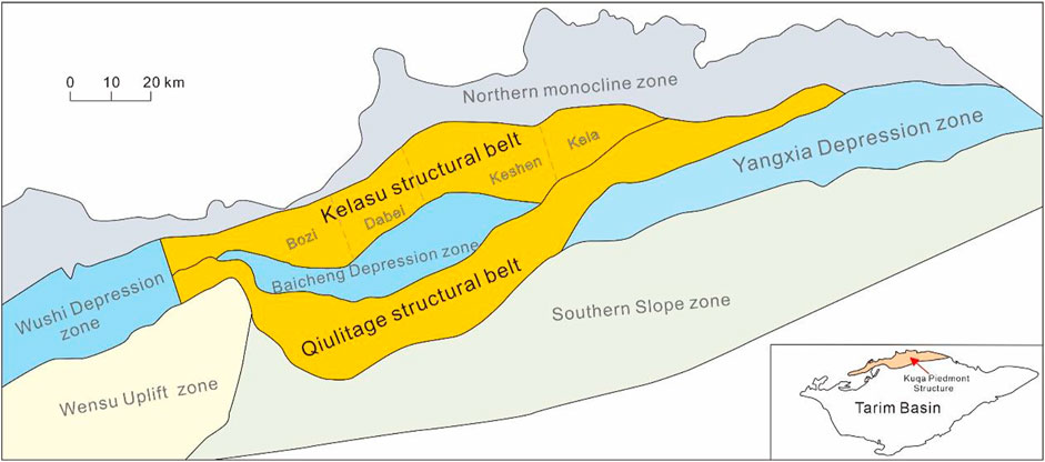
FIGURE 1. Kuqa Depression geological structure map.
The composite salt-gypsum layers of the Paleogene Kumugeliemu Group are divided into gypsum-salt rock section, mudstone section and salt rock section from bottom to top. The gypsum-salt rock section is mainly composed of gypsum rock and salt rock, intercalated with dolostone and limestone; the mudstone section is mainly composed of mudstone, with thin layers of gypsum rock intercalated, and mud gypsum rock can be seen; the salt rock section develops relatively pure and thick salt rock, locally mixed with more gypsum rock and sandy mudstone.
The salt rock samples of the Kumugeliemu Group were collected and prepared into 5 test samples with a size of 100 × 50 (mm × mm) (Table 1). The tests were carried out using the American MTS815 Flex Test GT rock mechanics test system (Rui et al., 2022a; Rui et al., 2022b). Creep tests require consideration of creep behavior under different confining pressures (axial compression) and temperatures, and the supplied salt rocks are highly rheological (Pan and Zhou, 2022). The test method is as follows: by controlling the principal stress σ1=125 MPa unchanged, starting from the initial stress σ3=120 MPa, σ1-σ3=5 MPa, the confining pressure (σ3) is reduced by 5 MPa in each stage and the axial pressure (σ1-σ3) is increased by 5 MPa, so as to ensure that the principal stress remains unchanged, and the pressure increases by 5 MPa step by step. Starting from 100°C, a total of 5 levels of temperature are designed, 110°C, 120°C, 130°C, and 140°C. The creep duration of the first 5 levels of deviatoric stress load is 3 h, and after 5 levels, it is changed to 2 h per grade.
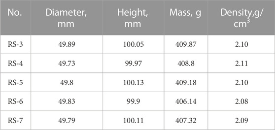
TABLE 1. Test sample parameters.
Considering different factors such as effective stress and temperature, triaxial creep tests at high temperature were carried out under actual confining pressure (axial compression) and temperature (Tan et al., 2020; Tan et al., 2021). The experimental temperatures, stress differences and corresponding strain rates are shown in Table 2.
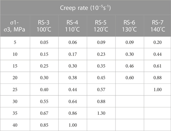
TABLE 2. Creep test data.
The results show that the creep displacement increases with the increase of temperature. When the temperature reaches more than 100°C, the creep displacement respectively reaches 100°C/22.14 mm, 110°C/26.09 mm, 120°C/31.59 mm, 140°C/53.32 mm, and the test result is rejected at 130°C because the sample is filled with oil. The results show that the temperature affects the overall strength of rock salt, resulting in weaker strength of samples (Figure 2). When the temperature is constant, the creep displacement increases with the increase of deviatoric stress; when the deviator stress is constant, the creep displacement increases with the temperature (Figure 3).
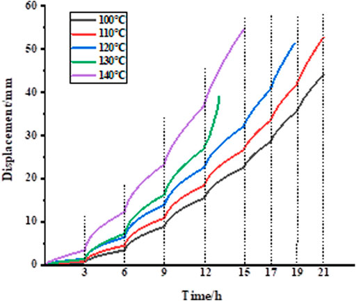
FIGURE 2. Creep time-displacement curve at high temperature.
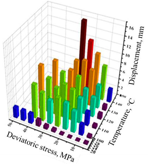
FIGURE 3. Variation trend of creep section displacement with deviatoric stress and temperature.
Comparing the creep test data of Tarim deep salt rock under high temperature and pressure with the creep test data at home and abroad, it is found that the differential stress of 10 MPa is an important contrast demarcation point. When the differential stress is less than 10 MPa, the creep rate of Tarim salt rock is higher than that of other blocks at the same temperature. When the differential stress is higher than 10 MPa, the creep rate is higher than that of most of the world’s salt rock creep experimental data (Figure 4).
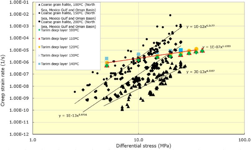
FIGURE 4. Comparison of data from the Tarim salt rock creep experiment and the world salt rock creep experiment.
Experimental data reveal the effect of temperature and differential stress on creep of salt rock. It can be seen that temperature and differential stress have a considerable magnitude of influence on the creep rate of salt rock, for example, the temperature ranges from 100°C–140°C, and the creep rate ranges from 3 × 10⁻⁶s−1 to 1 × 10⁻⁵s-1. While the differential stress varies from 5 to 40 MPa, the creep rate varies from 1 × 10⁻⁶s−1 to 1 × 10⁻⁵s−1.
According to the global mainstream knowledge, where the temperature is high and the stress value is relatively small, and the power law can be used to describe the steady creep of salt rock (Weertman, 1955), the steady creep rate of salt rock increase with the increase of temperature and differential stress (Li et al., 2022). Its expression can be summarized as a stress-independent power-law (non-Newtonian fluid flow) equation:
The experimental data were fitted by the power-defect function. First, the exponent n is fitted as below:
where
Then
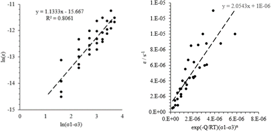
FIGURE 5. Fitting of
Salt rock creep is controlled by two main factors, temperature and differential stress. The depth of the layers affects temperature and in-situ stress. Well deviation affects the stress distribution around the well and determines the change of differential stress. It is difficult to verify the well deviation factor through laboratory experiments, so it is necessary to use a simulation method to analyze the effect of well deviation on creep.
Numerical simulations based on core tests can extend the real experimental environment to a wider range of simulations. A numerical model of the same scale of the core experiment was established, and the stress-strain relationship obtained from the experiment was input into the software platform as the constitutive model. According to the environment and loading conditions of the core experiment, the numerical simulation of the influencing factors of salt rock creep was carried out. The simulation is mainly divided into three steps. First establish a model for numerical simulation of core specimens. Second, use the creep constitutive model obtained from experimental data under deep environmental conditions, to carry out numerical simulation under experimental isothermal pressure conditions. Third, compare the numerical simulation results with the field data. The comparison shows that the simulation results are basically consistent with the experimental results, which verifies the accuracy of the model.
By using the method of combining core experiment and core scale numerical simulation, this paper analyze the influence of temperature and differential stress (i.e., axial pressure) on creep, using creep power-law constitutive relations between temperature and pressure in deep layers. Combined with the actual on-site situation, four sets of simulations were set up, the creep deformation of 40 h was used, and then the deformation under different axial pressures was calculated respectively. The relationship between the creep rate and the combination of axial pressure and temperature was established (Table 3; Figure 6).
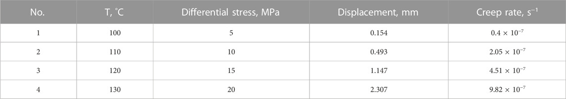
TABLE 3. Influence of four sets of temperature and differential stress superposition on creep of salt rock.
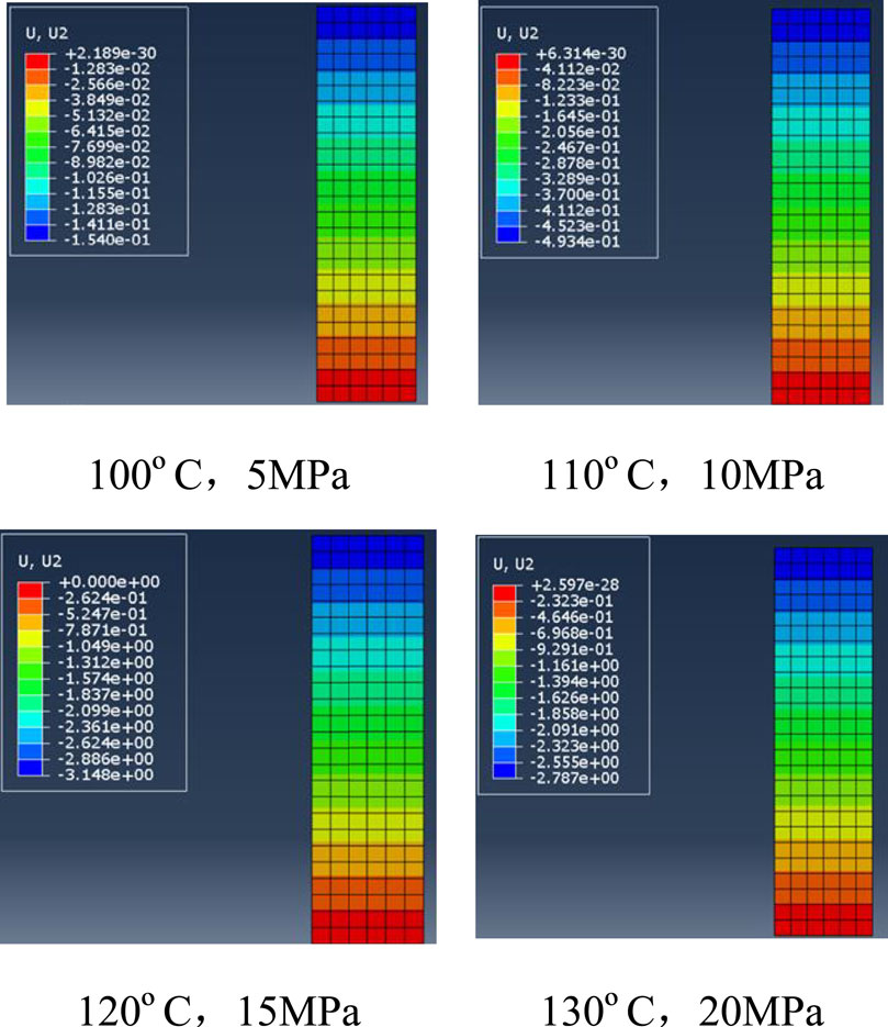
FIGURE 6. Creep deformation under different temperature and stress.
Creep simulations show an upward trend in creep rate with increasing differential stress and temperature combinations (Figure 7). From the data analysis, it can be seen that the creep rate increases from 0.4 × 10⁻⁷ s−1 to 9.82 × 10⁻⁷ s−1 as 100°C/5 MPa increases to 130°C/20 MPa, which shows a multiple growth.
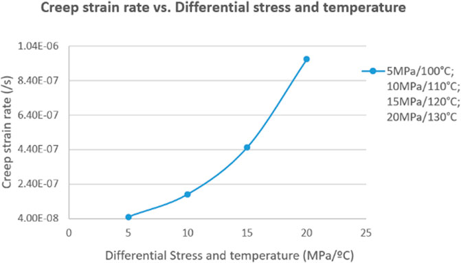
FIGURE 7. Creep Rate vs. Differential Stress Temperature Combination.
The stress around the well is affected by the in-situ stress and the deviation angle, and the stress around the well can be obtained by calculating the in-situ stress according to the deviation angle. Therefore, the well deviation factor can also be considered as the change of differential stress in essence. Considering the influence of the well deviation angle (differential stress) and temperature on the creep, using the creep constitutive relations between temperature and pressure in deep layers, four sets of simulations were set up, the creep deformation of 40 h was used, and then the deformation under different conditions was calculated respectively. The relationship between the creep rate and the combination of temperature and well deviation was established (Table 4; Figure 8).
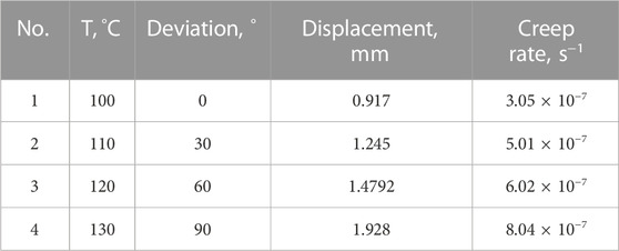
TABLE 4. Influence of four sets of temperature and deviation superposition on creep of salt rock.
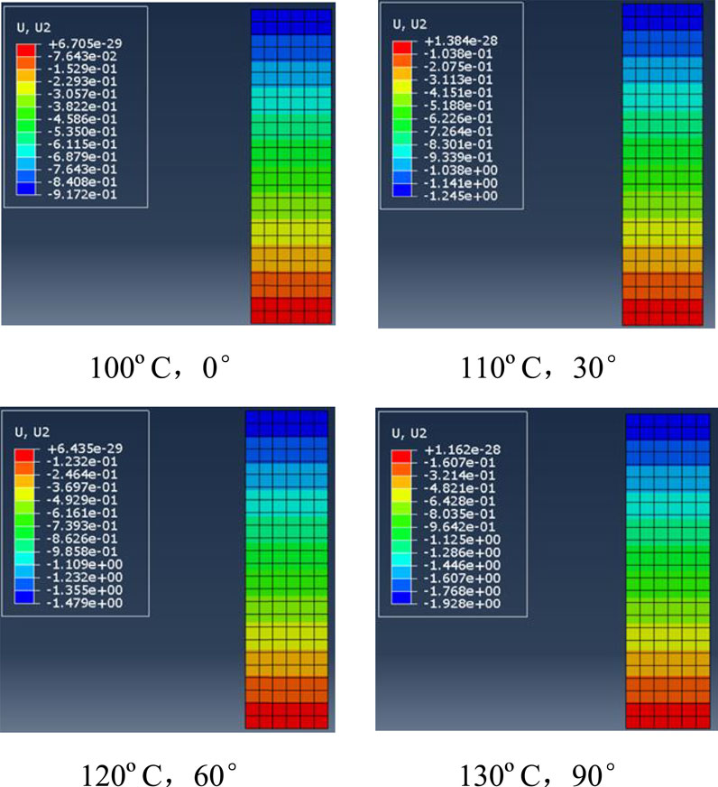
FIGURE 8. Creep deformation under different temperature and deviation.
Creep simulations show that the creep rate tends to increase as the combination of well deviation and temperature increases. When the deviation ranges from0° to 90°, the effect on the creep rate is similar to the effect of 5–6 MPa differential stress increase (Figure 9). From the data analysis, it can be seen that the creep rate increases from 3.05 × 10⁻⁷ s−1 to 8.04 × 10⁻⁷ s−1 as 100°C/0° increases to 130°C/90°.
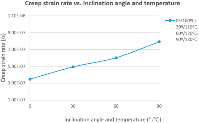
FIGURE 9. Relationship between creep rate and well inclination angle (differential stress condition) and temperature combination.
Through multi-factor comprehensive simulation, it can be seen that temperature and differential stress are the key controlling factors of creep, and well deviation angle has an important influence on creep. Its essence is to change the stress distribution around the well, which can be directly converted into the change of differential stress.
The wellbore stability of the composite salt-gypsum layers is affected by the rock mechanics, in-situ stress, well deviation and drilling fluid density. An integrated model of in-situ stress, the composite salt-gypsum layers, borehole and drilling fluid is established (Figure 10). Steps are as follows.
(i) Combining a stratigraphic model based on the superimposed relationship of multiple layers of mudstone and salt rock, with engineering data and creep mechanics test data, establish a mechanical model that reflects the vertical distribution of real stratigraphic lithology.
(ii) According to the designed well trajectory, establish a deviated well model under vertical multi-layer conditions that reflects the real deviation angle.
(iii) Apply vertical stress and minimum horizontal stress to the model. In the salt layers, due to the small differential stress, the principal stress values applied to the salt layer in all directions are equal.
(iv) The liquid column pressure generated by the density of drilling fluid is simulated by the pressure exerted on the inner wall of the wellbore.
(v) The reduction ratio is characterized by the ratio of the shrinkage displacement of the salt layers in the direction perpendicular to the deviated well wall and the borehole radius.
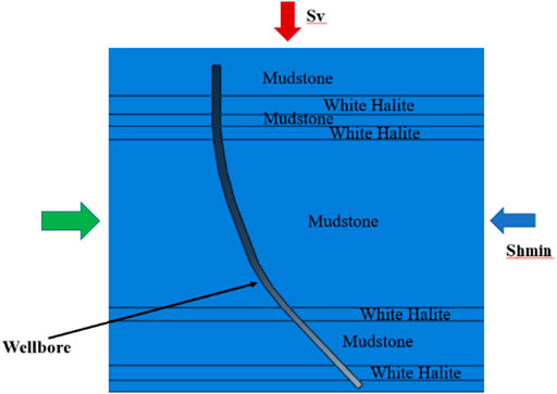
FIGURE 10. Deviated well model under 2D vertical multi-layer condition.
The creep shrinkage is simulated through the actual drilling and sticking situation on site. At a given reduction ratio, the drilling fluid density required to control creep is calculated.
According to the main deviation angle drilling through the composite salt-gypsum layer, when modeling the directional well, the angle is mainly set to 45° and 60° for simulation research. Table 5 illustrates the specific parameters at different deviation angles. Figure 11 shows the schematic diagram of the mechanical model at different deviation angles. Figure 12 shows the differential stress distribution at different deviation angles. Figure 13 shows the creep shrinkage results when the drilling fluid density is 2.3 g/cm3.
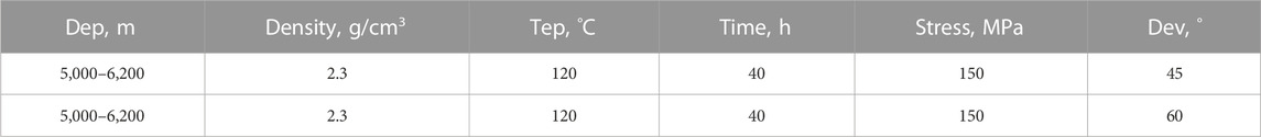
TABLE 5. Specific parameters for creep simulation of salt rock with well inclination of 45° and 60°.
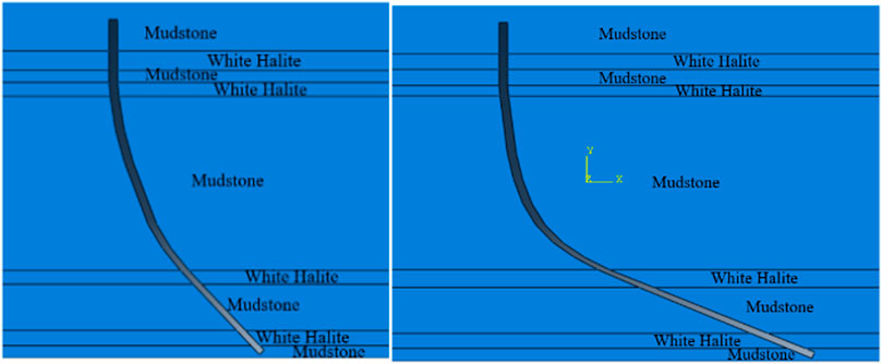
FIGURE 11. Schematic diagram of the well inclination model of 45° and 60°.
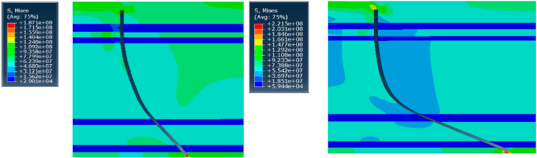
FIGURE 12. Differential stress distribution at 45° and 60° inclination.
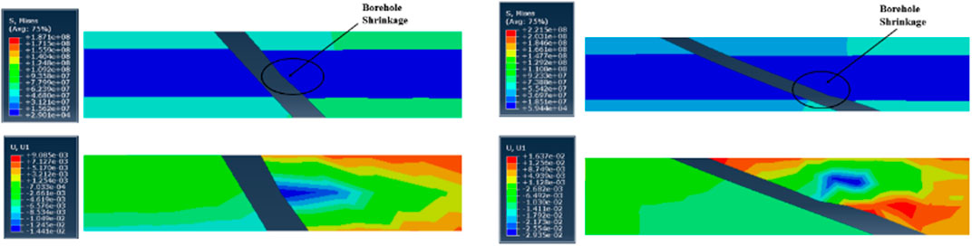
FIGURE 13. Creep shrinkage results when the drilling fluid density is 2.3 g/cm3 when the well inclination is 45° and 60°.
When the well deviation is 45°, the differential stress distribution of the model shows that the differential stress in the salt layers is very small (close to the isotropic stress condition), only about 0.03 MPa, while he differential stress of mudstone is 40–80 MPa, the maximum value of borehole shrinkage is 1.44 × 10⁻² m, and the shrinkage rate is about 11%. When the well deviation is 60°, the differential stress in the salt layers is also very small, about 0.06 MPa, while the mudstone differential stress is 60–90 MPa, the maximum value of borehole wall shrinkage is 1.70 × 10⁻² m, and the shrinkage rate is about 17%.
By establishing a two-dimensional mechanical model for deviated wells in composite salt-gypsum layers, the paper simulates the drilling fluid density that can resist salt rock creep with different depths and stresses under the conditions of 45° and 60° well deviation respectively (Table 6). Assuming that the creep shrinkage of salt rock that causes sticking is 5%, the drilling fluid density required to prevent sticking is calculated based on the field data of several wells, and the intersection chart of depth, stress, well deviation and creep-resistant density is established (Figures 14, 15).
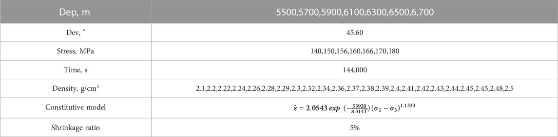
TABLE 6. Simulation parameters of well.
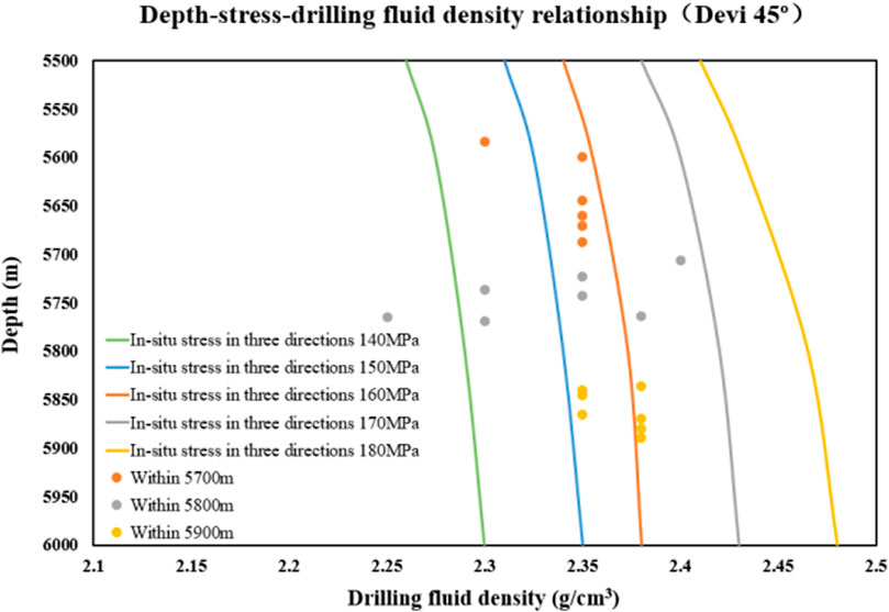
FIGURE 14. Intersection chart of salt rock creep of depth, stress and drilling fluid density (45° inclination).
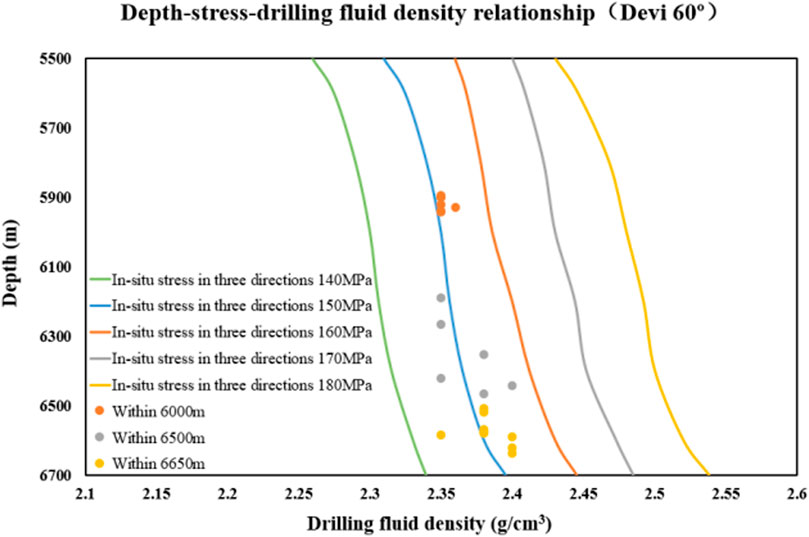
FIGURE 15. Intersection chart of salt rock creep of depth, stress and drilling fluid density (60° inclination).
The depth ranges from 5,500 to 6,000 m and the temperature ranges from 130°C to 150°C in this chart. Each colored line in the chart represents the three-dimensional in-situ stress of the salt rock, which is also the liquid column pressure required to balance the creep of the salt rock. The value of different colors is ranges from 140 to 180 MPa, and the ground stress of the same line is the same. The depth of sticking and the corresponding drilling fluid density data in the Bozi block are put into the chart. When the points with different colors are on the left side of the corresponding color curve, it means that the selected drilling fluid density is too small to resist salt rock creep. It also proved that the simulation was accurate.
The simulation chart shows that with the increase of the triaxial in-situ stress, that is, the increase of the formation depth, the density of the drilling fluid used to suppress the same shrinkage ratio increases, otherwise the sticking will show a more serious trend. Comparing the well deviation of 45° and 60°, under the same in-situ stress or depth, the density of drilling fluid required for 60° is slightly higher than that of 45° to maintain the same diameter reduction rate. It can be seen from the simulation results that the change of the well deviation angle will have an important influence on the creep shrinkage and jamming of the directional well in the composite salt-gypsum layers.
During the drilling process of 5,674–5,711 m in Well Bz A, serious sticking accidents occurred continuously, where the lithology is salt rock and muddy salt rock, the well inclination angle is 39°–42°, and the drilling fluid density is 2.2 g/cm3. In order to reduce sticking, the creep rate simulation of composite salt-gypsum layers was carried out to optimize the density of creep-resistant drilling fluid. Well Bz A is a deviated well oriented in the composite salt-gypsum layers. The analysis shows that when the formation depth is greater than 5,510 m, the jamming situation is more serious. Based on the actual drilling situation, the simulation depth is set to be 5,500–6,000 m, the deviation angle is set to be 45°, the ground stress is set to be 130, 136, 146, 150, 156 and 160 MPa respectively according to the depth change, and the shrinkage ratio is set to be 5%, and then the relations of depth, stress and drilling fluid density are simulated and the chart is drawn (Figure 16). On this basis, the actual drilling fluid density on site is put on the chart for comparison.
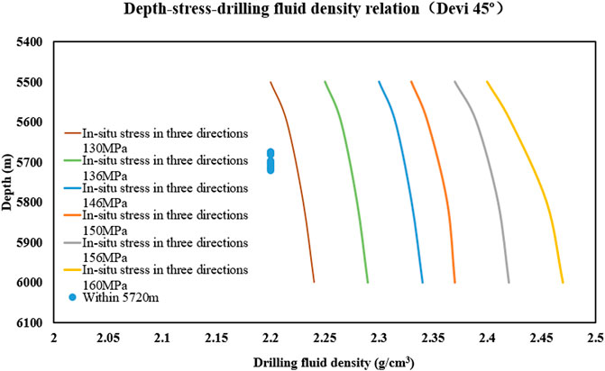
FIGURE 16. Intersection chart of salt rock creep of depth, stress and drilling fluid density of Bz A.
It can be seen that when the in-situ stress is 130 MPa and the depth is from 5,500–6,000 m, the recommended drilling fluid density is 2.20–2.24 g/cm3. When the in-situ stress is 136 MPa, the depth is from 5,500–6,000 m, and the recommended drilling fluid density is from 2.26–2.29 g/cm3. When the in-situ stress is 146 MPa, the depth is from 5,500–6,000 m, and the recommended drilling fluid density is from 2.30–2.33 g/cm3. When the in-situ stress is 150 MPa, the depth is from 5,500–6,000 m, and the recommended drilling fluid density is from 2.35–2.38 g/cm3. When the in-situ stress is 156 MPa, the depth is from 5,500–6,000 m, and the recommended drilling fluid density is from 2.38–2.42 g/cm3. When the in-situ stress is 160 MPa, the depth is from 5,500–6,000 m, and the recommended drilling fluid density is from 2.40–2.47 g/cm3. According to the chart, the density of the drilling fluid can be appropriately increased to effectively control the shrinkage ratio. Therefore, that density of drilling fluid was increased to 2.23 g/cm3 in field application, and the sticking at 5,873–5,966 m was relieved. The field application of anti-creep measures has achieved good results. The field application of anti-creep measures has achieved good results.
When the drilling fluid density is too high, it is easy to leak in the salt interlayer, so it is unreasonable to simply increase the drilling fluid density to resist the salt rock creep. Salt rock reaming was adopted in the field to deal with the problem of creep sticking. The fracture pressure was taken as the upper limit of drilling fluid density, and the salt creep rate under this density was calculated. The limit time of periodic reaming was calculated according to the creep variable of reduced diameter sticking, so as to prevent creep. Based on the creep model established in this study, 5% diameter reduction was set as the standard to judge stuck drilling, and the minimum reaming time was calculated under different drilling fluid densities. Drilling stuck occurred in Bz 9 well at a depth of 6,200–6400 m with 2.36 g/cm3 drilling fluid density. Actual drilling showed that the time from the first drilling through the stuck point depth to the occurrence of stuck was 41.7 h, within this time the bit successfully passed the stuck point. Under the condition of the simulated drilling fluid density of 2.36 g/cm3, the hole diameter at the stuck point reduced by 5% in an average time of 39.5 h, which corresponds well with the actual stuck time, verifying the practicability of this study.
This study establishes a model and method for numerical calculation of wellbore stability in two-dimensional directional wells, and it is an effective way to simplify the stress calculation. Three-dimensional modeling needs to be used in order to set up a more realistic model based on multiple parameters such as geostress distribution, well deviation angle, and azimuth angle. Due to the three-dimensional borehole mechanics calculation and demonstration along the shaft axis direction and each depth section direction in directional well are complicated, the three-dimensional mechanical analysis of wellbore creep will be carried out in the future study.
The high temperature and high pressure creep test of salt rock shows that temperature and differential stress are the most important factors affecting creep, and temperature directly affects the overall strength of salt rock. When the temperature reaches above 100°C, the creep displacement increases faster as the temperature increases. When the temperature is constant, the creep displacement increases with the increase of the differential stress. By means of simulation, the effect of well deviation on creep is analyzed, which shows that the well type (well deviation angle) has an important influence on creep. Its essence is to change the stress distribution around the well, which can be directly interpreted to be the change of differential stress.
The differential stress of Tarim salt layer is generally less than 10 MPa. Under the same temperature conditions, the creep rate of Tarim salt rock is higher than that of other similar blocks in the world.
By establishing a two-dimensional mechanical model for deviated wells in composite salt-gypsum layers, the paper simulates the relations of deviation angle, depth, stress and drilling fluid density. Combined with the field drilling data of multiple wells, the intersection chart of stress, deviation angle and drilling fluid density resisting creep are established to analyze the drilling fluid density required to prevent sticking. The chart of creep-resistant drilling fluid density in Bz A well was established to guide the adjustment of drilling fluid density on site, which effectively solved the problem of sticking and verified the effectiveness of the method.
The original contributions presented in the study are included in the article/Supplementary Materials, further inquiries can be directed to the corresponding author.
All authors listed have made a substantial, direct, and intellectual contribution to the work and approved it for publication.
The authors are grateful for the Project Support of NSFC (5217040048) and CNPC (2021DJ4100).
CF, QZ, ZC, ZL, and JF were employed by CNPC Engineering Technology R&D Co., Ltd. HZ was employed by PetroChina Tarim Oilfield Company.
The remaining authors declare that the research was conducted in the absence of any commercial or financial relationships that could be construed as a potential conflict of interest.
All claims expressed in this article are solely those of the authors and do not necessarily represent those of their affiliated organizations, or those of the publisher, the editors and the reviewers. Any product that may be evaluated in this article, or claim that may be made by its manufacturer, is not guaranteed or endorsed by the publisher.
Chen, S., Zhang, H., Yin, G. Q., Yuan, F., Ju, Y., and Li, C. (2014). Study on the prediction of the sticking time of gypsum salt rock creep shrinkage. Technol. Superv. Petroleum Industry 30 (10), 32–35. doi:10.3969/j.issn.1004-1346.2014.10.011
Du, S. H., Hou, B., and Cui, Z. (2021). ”Numerical simulation of creep in salt-gypsum formation of directional well in Xinghuo Area,” in ARMA/DGS/SEG 2nd international geomechanics symposium, virtual symposium, online, November 2021.
Fang, C., Zhang, H., Chen, Z. W., Chen, Y. S., Feng, Y. C., Lin, Z. L., et al. (2022). Discussion on leakage mechanism and prevention measures of geological engineering integration: A case from salt of palaeogene in the Kuqa Piedmont structure in Tarim Basin, China. Oil Drill. Prod. Technol. 44 (06), 1–11. doi:10.13639/j.odpt.2022.06.004
Li, S. Y., Fang, C., Chen, C. W., Xiang, D. G., Li, F. Y., and Huang, H. (2022). Analysis and research on borehole shrinkage mechanisms and their control in directional wells in deep composite salt formations. Lithosphere 2022 (1), 5863198. doi:10.2113/2022/5863198
Liang, C., Liu, J. F., Chen, Z. W., Lu, G. D., Lyu, C., and Ren, Y. (2022). Study on salt rock creep characteristics of wellbore under high temperature and high pressure. J. Porous Media 25 (3), 51–69. doi:10.1615/jpormedia.2021040126
Moosavi, M., Jafari, M., and Rassouli, F. (2009). “Investigation on creep behavior of salt rock under high temperature with impression technique,” in Proceedings of the ISRM International Symposium on Rock Mechanics-SINOROCK 2009, China, May 2009
Orlic, B., Wollenweber, J., and Geel, C. (2019). “Formation of a sealing well barrier by the creep of rock salt: Numerical investigations,” in Proceedings of the 53rd US Rock Mechanics/Geomechanics Symposium, New York, NY, USA, June 2019 (American Rock Mechanics Association).
Orozco, S., Pino, J., and Paredes, M. (2018). “Managing creep closure in salt uncertainty while drilling,” in Proceedings of the 52nd US Rock Mechanics/Geomechanics Symposium, Washington, June 2018 (American Rock Mechanics Association).
Pan, X., and Zhou, X. (2022). Damage analysis of sandstone during the creep stage after high-temperature heat treatment based on NMR Technology. Rock Mech. Rock Eng. 55 (12), 7569–7586. doi:10.1007/s00603-022-03048-7
Rui, Y. C., Zhou, Z. L., Lu, J. Y., Ullah, B., and Cai, X. (2022a). A novel AE source localization method using clustering detection to eliminate abnormal arrivals. Int. J. Min. Sci. Technol. 32 (1), 51–62. doi:10.1016/j.ijmst.2021.11.004
Rui, Y. C., Zhou, Z. L., Cai, X., Lan, R. Y., and Zhao, C. C. (2022b). A novel robust AE/MS source location method using optimized M-estimate consensus sample. Int. J. Min. Sci. Technol. 32 (4), 779–791. doi:10.1016/j.ijmst.2022.06.003
Tan, P., Jin, Y., and Pang, H. W. (2021). Hydraulic fracture vertical propagation behavior in transversely isotropic layered shale formation with transition zone using XFEM-based CZM method. Engineering Fracture Mechanics 248, 107707.
Tan, P., Pang, H. W., Zhang, R. X., Jin, Y., Zhou, Y. C., Kao, J. W., et al. (2020). Experimental investigation into hydraulic fracture geometry and proppant migration characteristics for southeastern Sichuan deep shale reservoirs[J]. Journal of Petroleum Science and Engineering 184, 106517.
Weertman, J. (1955). Theory of steady-state creep based on dislocation climb. J. Appl. Phys. 26 (10), 1213–1217. doi:10.1063/1.1721875
Zeng, D. Z., Lin, Y. H., Lu, Y. F., Zhu, D. J., and Li, L. W. (2012). Numerical simulation of hole creep shrinkage for composite rock salt layers. J. Geomechanics 18 (02), 158–164. doi:10.3969/j.issn.1006-6616.2012.02.006
Zeng, Y. J., Wang, W. L., and Shi, B. Z. (2005). Study on creep features of deep salt and gypsum beds and its applications in drilling operations. Pet. Drill. Tech. 5, 51–54. doi:10.3969/j.issn.1001-0890.2005.05.011
Keywords: Tarim Basin, composite salt-gypsum layers, creep sticking, geomechanics, drilling fluid density
Citation: Fang C, Li S, Zhao Q, Zhang H, Chen Z, Huang H, Lin Z, Fan J and Liu E (2023) Influence of mechanical characteristics of deep composite salt-gypsum layers on safe drilling of directional wells: a case study of Palaeogene in the Kuqa Piedmont structure, Tarim Basin, China. Front. Earth Sci. 11:1130805. doi: 10.3389/feart.2023.1130805
Received: 23 December 2022; Accepted: 10 May 2023;
Published: 15 June 2023.
Edited by:
Jun Lu, Shenzhen University, ChinaReviewed by:
Dawei Hu, Chinese Academy of Sciences (CAS), ChinaCopyright © 2023 Fang, Li, Zhao, Zhang, Chen, Huang, Lin, Fan and Liu. This is an open-access article distributed under the terms of the Creative Commons Attribution License (CC BY). The use, distribution or reproduction in other forums is permitted, provided the original author(s) and the copyright owner(s) are credited and that the original publication in this journal is cited, in accordance with accepted academic practice. No use, distribution or reproduction is permitted which does not comply with these terms.
*Correspondence: Chao Fang, ZmFuZ2NoYW9kckBjbnBjLmNvbS5jbg==
Disclaimer: All claims expressed in this article are solely those of the authors and do not necessarily represent those of their affiliated organizations, or those of the publisher, the editors and the reviewers. Any product that may be evaluated in this article or claim that may be made by its manufacturer is not guaranteed or endorsed by the publisher.
Research integrity at Frontiers
Learn more about the work of our research integrity team to safeguard the quality of each article we publish.