 Feng Chen
 Xuebin Wang
 Xueyuan Bai2
- 1School of Mechanics and Engineering, Liaoning Technical University, Fuxin, China
- 2Institute of Computational Mechanics, Liaoning Technical University, Fuxin, China
Given the problems of serious asymmetric deformation and the difficulty in supporting right-angled trapezoidal roadways during the mining process, we established a mechanical model of surrounding rock for a right-angled trapezoidal roadway, determined the relationship between the deflection and tilt angle of the roadway roof, and determined that the typical failure mode of right-angled trapezoidal roadways is the upper slip of the high side. Two optimized support schemes are proposed, in which a constant resistance large deformation (CRLD) bolt + ordinary I-steel or a portal energy absorbing hydraulic (PEAH) support + ordinary bolt is used as the main support instead of an ordinary bolt + ordinary I-steel. Numerical simulation analysis shows that the aforementioned optimized support schemes can reduce the deformation, acoustic emission (AE) quantity, and AE energy of rock surrounding roadways and change how surrounding rock releases energy from main earthquake type to swarm earthquake type. The support scheme with CRLD bolt + ordinary I-steel or PEAH support + ordinary bolt as the main support can reduce the deformation of a roadway’s high side to 0.192 and 0.145 m, respectively. This shows that the two optimized schemes can effectively improve the overall bearing capacity and integrity of the rock surrounding roadways, which can be applied in the field.
1 Introduction
The demand for coal is increasing all over the world with construction due to rapid economic development. Coal mines are constantly deepening because of the reduction in shallower resources. Because the geological environment of deep roadways is becoming increasingly complex, sudden engineering disasters and major accidents caused by the non-linear large deformation of the surrounding rock frequently occur (Yang et al., 2016; Kang et al., 2020; Chen et al., 2021a; Wang et al., 2021). Supporting materials including ordinary bolts, anchor cables, and I-steel can no longer adapt to the instantaneous large deformation of the surrounding rock in deep roadways. The fundamental reason is that these supporting materials have small deformations, low support resistance, and absorb less energy (Wang et al., 2015; Wang et al., 2016; Hou, 2017; Kang et al., 2018). Therefore, it is necessary to use materials appropriate to large deformation, high supporting resistance, and greater energy absorption when large deformations occur in roadways.
Increasingly deep coal mining has led to an increase in the complexity of the geological environment in which the rock surrounding roadways is located. The stress conditions of high ground pressure and strong mining, as well as external factors of roadway shape and support, lead to severe deformation of this rock (Zhang and Gao, 2002; Kang et al., 2009; Xie et al., 2010; Cao et al., 2014; Le et al., 2017; Wang et al., 2018; Kang, 2021). The asymmetry of right-angled trapezoidal roadways often leads to asymmetry in the rock pressure, which is more likely to induce large deformations in the roadway.
Many have studied the deformation mechanism of right-angled trapezoidal roadways, ground pressure behavior laws, and the control technology of the surrounding rock. Zheng Zheng et al. established the mechanical model of inclined roof roadways along the goaf, deduced the influence range of the internal stress field of inclined coal seams, and then proposed asymmetrical surrounding rock support technology of prestressed bolt + high-strength anchor cable + truss (Zheng et al., 2019). Chen Xinnian et al. observed that the surrounding rock stress of right-angled trapezoidal roadways in inclined coal seams has obvious asymmetrical characteristics, which lead to serious asymmetric failure of these roadways (Chen et al., 2019a). Ma Jie et al. studied the failure law and control technology of right-angled trapezoidal roadways under the influence of deep mining and proposed the control method for the rock surrounding roadways of combined support + high side reinforcement + low side pressure relief (Ma et al., 2022). Wang Xufeng et al. established a mechanical model for the surrounding rock of mining roadways in “Three Soft” coal seams with a large dip angle and systematically analyzed the stress of the roof, two sides, and floor (Wang et al., 2017). Xiong Xianyu and Dai Jun designed a support scheme with a bolt + metal mesh as a primary support and an anchor cable as secondary reinforcement according to the stress-deformation asymmetric characteristics of the surrounding rock of right-angled trapezoidal roadways in gently inclined soft coal seams (Xiong and Dai, 2020). Chen Xinnian et al. systematically analyzed the horizontal stress and horizontal displacement of the surrounding rock of right-angled trapezoidal roadways in an inclined coal seam of the Shitanjing mine (Chen et al., 2019b). Su Xuegui et al. analyzed the variation law of the surrounding rock stress and displacement of trapezoidal roadways under the conditions of conventional symmetrical support and asymmetric strong support (Su et al., 2016). These studies fully demonstrate diverse failure forms and supporting methods of roadway surrounding rock, but research on right-angled trapezoidal roadways mostly focuses on the excavation stage. Roadway deformation under the influence of the mining face is more serious in practical engineering, so it is necessary to study the deformation and control of right-angled trapezoidal roadways under the influence of coal mining.
Here, we take a right-angled trapezoidal roadway in the 21041 mining face of a coal mine in Henan Province, China, as the engineering background and analyze the deformation characteristics and causes of right-angled trapezoidal roadways under the influence of coal mining. We study the relationship between the deflection and inclination angle of the roof, as well as the typical failure mode of the upper sliding of the roadway high side. The optimized scheme of CRLD bolt + ordinary I-steel or PEAH support + ordinary bolt as the main support instead of ordinary bolt + I-steel is proposed. Using RFPA software, the support effects of different support schemes are compared and analyzed from aspects such as stress, deformation, and acoustic emissions. The results of numerical simulations show that two optimized schemes can control the deformation of rock surrounding roadways and can be applied in the field.
2 Engineering background
This paper takes the lower roadway of the 21041 mining face of a coal mine in Henan Province of China as the engineering background (Figure 1). The hydrogeological conditions of this roadway are simple. The earth surface of the mining face is barren mountains and hills, with no rivers, ponds, and reservoirs. The ground elevation of this lower roadway is +490 m ∼ +435 m, and the elevation of the mining face is −213 m ∼ −50 m. The east of this mining face is the goaf of the 31010 mining face, the south is the coal pillar protected by the Putushan fault in the mine, the west is the solid coal body that has not been mined, and the north is adjacent to the 21021 mining face. The overall structural form of the coal strata in the lower roadway of the 21041 mining face is monoclinal. The physical and mechanical properties of the roof and floor rock mass of the coal seam are shown in Table 1. According to the early stage of roadway excavation, the roof of the coal seam has a large decline, is full of ballast, and is uneven. The two sides of the roadway are cracked and separated from the layer, and a large sliding block appears on the upper part of the high side of the roadway. Because it is forbidden to take photos in the coal mine, the roadway damage image was not obtained.
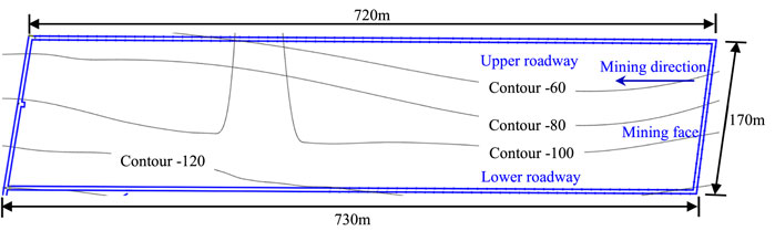
FIGURE 1. 21041 mining face schematic diagram.
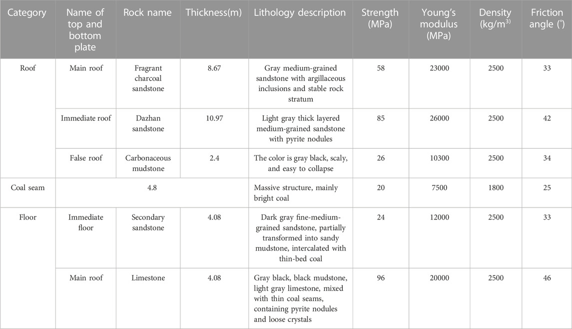
TABLE 1. Rock mass on roof and floor of coal seam.
3 Theoretical analysis of the deformation law of rock surrounding roadways
Field observation has revealed that the upper part of the high side of the rock that surrounds right-angled trapezoidal roadways frequently manifests a sliding deformation. In addition, because the strength and stiffness of the roadway’s roof are low, it is very easy to cause delamination damage and large deformation. The simplified model of roof stress is shown in Figure 2. FR is the restraint force at both ends of the roof, FN is the axial force on the roof, Me is the couple moment of the roof, q is the load concentration of the uniformly distributed load on the roof, and l and θ are the span and inclination of the roof, respectively.

FIGURE 2. Roof force diagram.
According to the mechanics of materials, it can be known that the differential formula of deflection crankshaft when a beam undergoes bending deformation is
The beam corner is generally small in practical engineering, so the value is
We ignore the horizontal stress between the rock layers and simplify the roof strata into a beam structure. Using Formula 2, the approximate differential formula of the roof deflection crankshaft is obtained as
Integrating the aforementioned formula twice, we get
where ω is the roof deflection, C and D are integral constants, and EI is the roof bending stiffness.
According to the displacement boundary condition, at x=0 and x=l, ω=0. C=D=0 can be obtained by substituting this condition into Formula 4.
The beam deflection formula is
When x=l/2, the maximum roof deflection is
It can be seen from Formula 6 that the deflection of an inclined roof is directly proportional to q and l4 and inversely proportional to EI. Therefore, the increase of the roof bending stiffness EI can reduce the roof deflection. In addition, the maximum deflection of an inclined roof is proportional to the roof inclination angle θ. It can be seen from Table 1 that the false roof is carbonaceous mudstone, with a thickness h=2.4 m and an elastic modulus E=10300 MPa. Taking the plane problem, I=bh3/12 of the rock stratum (take b=1), then I=1.152 m4, referring to the lower roadway roof of 21041 mining face l=5 m, q=15.75×10⁶ N/m. Substituting the aforementioned parameters into Formula 6, we get
The ωmax of different roof inclination angles can be obtained by Formula 7. When θ is 5° to 30°, the ωmax and difference of ωmax are shown in Figures 3 and 4, respectively. The aforementioned two values have a quadratic function relationship with the roof inclination angle θ, and the fitting degree index R2 is as high as 0.99 or more. This shows that the fitting degree between the estimated value of the trend line and the corresponding actual data is high, and thus the reliability of the trend line is high.

FIGURE 3. Variation characteristics of maximum roof deflection ωmax.
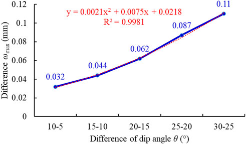
FIGURE 4. Variation characteristics of the difference of the maximum roof deflection.
Two coal wall sides of a right-angled trapezoidal mining roadway very easily form endogenous cracks under the influence of mining. If the support is improper, the two sides are prone to slip and lead to rib spalling. The surrounding rock of the roadway’s high side is cut to form a slip surface. The limit equilibrium analysis method of the slope rock mass proposed by Bardon is used to divide the unstable rock mass into blocks and assume that the tensile strength between the blocks is 0. Here, vertical stress is mainly considered, and horizontal stress is ignored. A mechanical model of a high side-slip surface is established (Figure 5).

FIGURE 5. Force diagram of roadway high side.
It can be seen from the stability calculation that the stress on the sliding surface increases continuously from points A to D in a simple cumulative way. When the stress of point D reaches the rock strength limit, it meets the Mohr–Coulomb criterion |τ| >σtanφ+c. The high side will form an inclined tensile crack CD under the action of high stress, which will affect the stability of the roadway high side and even cause the destruction of the entire roadway. Taking the tensile crack CD as the boundary, the ABCD region is unstable, and the CDE region is stable. An equilibrium formula can be obtained by combining virtual work theory and the slope stability principle:
where C is the cohesion of coal and rock in the two sides of the roadway, H is the relatively stable critical height, γ is the bulk density of coal and rock, φ is the friction angle in the coal and rock, v is the moving speed of the sliding rock mass, and β is the angle between the sliding surface and the vertical direction.
We solve Formula 8 to get
If the influence of the uniform load q is not considered, the maximum value Hmax of the relative stability critical degree is
If the uniformly distributed load q is considered, the Hmax will be further reduced. When the height of the roadway high side is greater than Hmax, the roadway side is easily damaged, and larger sliding blocks are more likely to appear. If the high side deforms greatly, it can even lead to instability of the whole roadway bearing structure.
4 Optimized design of roadway support
4.1 Support body
4.1.1 Introduction to CRLD bolt
The CRLD bolt is composed of a constant resistance device, bolt body, connecting sleeve, pallet, and nut (Figure 6) (He et al., 2014a; He et al., 2014b; He and Guo, 2014; Li et al., 2016). The constant resistance device includes a constant resistance sleeve and a bolt body. The inner surface of the constant resistance sleeve and the outer surface of the bolt body are both threaded structures, reducing the self-weight of the CRLD bolt. The constant resistance device is sleeved on the tail of the bolt body, and the tray and nut are sequentially installed at the tail of the constant resistance device. The constant resistance device and the bolt body are joined with a connecting sleeve.
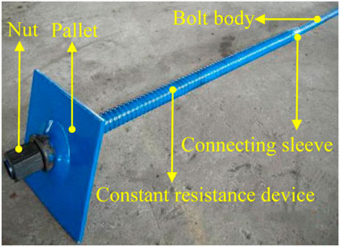
FIGURE 6. Structure of the CRLD bolt.
The design constant resistance of the CRLD bolt is 80%–90% of the yield strength of the bolt body material, ensuring that when the constant resistance works, the bolt body will not be plastic and deformed due to the external load exceeding its yield strength. Many coal mines in China use CRLD bolts to support roadways. The Xin’an Coal Mine adopted coupling support technology with CRLD bolts as the main body; field application results show that the adoption of this technology can ensure roadway stability during mining (Figure 7).
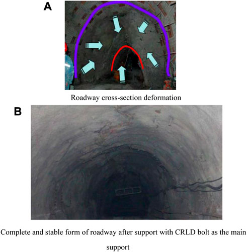
FIGURE 7. Comparison of before and after roadway support in Xin’an Coal Mine, Henan Province, China. (A) Roadway cross-section deformation. (B) Complete and stable form of roadway after support with the CRLD bolt as the main support.
4.1.2 Introduction to portal energy absorbing hydraulic (PEAH) support
The PEAH support is composed of a beam, two energy-absorbing hydraulic props, and a base (see Figure 8) (Pan et al., 2020a; Pan et al., 2020b). The designed working resistance of this support is 3300 kN. This support has been applied in more than 20 mines in China. It compensates for the insufficient strength of ordinary I-steel or U-shaped shed-lifting support due to its high support strength and good structural stability. The support pressure of the roadway can be regulated by the hydraulic cylinder, which has good pressure yielding characteristics. The hydraulic prop is composed of an oil cylinder, movable column, valve, and other parts, and the high-pressure liquid (special oil or emulsion) in the oil cylinders provides support for the hydraulic prop, which is a constant resistance prop. This can basically achieve constant working resistance through the regulation of the safety valve.

FIGURE 8. PEAH support structure.
4.1.3 Optimized support scheme
Because there are obvious deformations and cracks around the roadway under the original support scheme’s ordinary bolt + I-steel, we used the aforementioned support materials to formulate two sets of optimized support schemes.
Optimized Support Scheme I: we take CRLD bolt + ordinary I-steel as the main support and arrange ordinary I-steels and CRLD bolts on the left side, right side, and roof of the roadway; the spacing of the bolts is 600 mm.
Optimized Support Scheme II: we take PEAH support + ordinary bolt as the main support and arrange ordinary bolts on the left side, right side, and roof of the roadway; the spacing of the bolts is 600 mm. The height of the PEAH support is adjusted so that its support beam is close to the roadway roof.
In order to save costs, the support scheme with CRLD bolt + PEAH support as the main support was not considered.
4.2 Introduction to RFPA software
In 1995, Professor Tang from China developed RFPA (realistic failure process analysis) software to fully consider the characteristics of non-linearity, heterogeneity, and anisotropy associated with the rock fracture process.
RFPA software assumes that the mechanical properties of discretized microscopic units obey the Weibull statistical distribution law to establish a relationship between the mechanical properties of microscopic and macroscopic media. The Weibull statistical distribution function is described by Formula 11.
where α represents element mechanical properties, such as elastic modulus and compressive strength; α0 represents the average value of element mechanical properties; m is the property parameter of the distribution function, whose physical meaning reflects the uniformity of the material, and which is defined as the uniformity coefficient of materials; φ(α) is the statistical distribution density of element mechanical properties.
Formula 11 reflects the non-uniform distribution of the microscopic mechanical properties of a medium material. The unit mechanical properties are concentrated in a narrow range with the increase of the homogeneity coefficient m, indicating that the properties of the material (rock) medium are relatively homogeneous. On the other hand, when the homogeneity coefficient m decreases, the distribution range of the unit’s mechanical properties becomes wider, indicating that the unit’s properties tend to be inhomogeneous. Figure 9 shows the distribution of elastic modulus or strength of materials with different uniformity coefficients (α represents mechanical property parameters such as elastic modulus or strength).
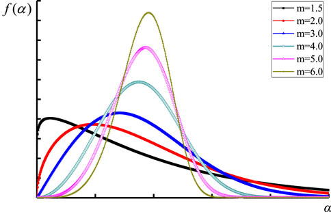
FIGURE 9. Distribution of the mechanical properties of materials with different homogeneity indexes m.
We take the elastic modulus as an example to introduce the assignment of mechanical property parameters of model primitives in RFPA software; the integral of the Weibull distribution function of the elastic modulus E based on Formula 11 is
where the statistical number of elements with elastic modulus is E.
A sample space is composed of elements formed by the statistical distribution of Formula 12. The integral space distribution is different due to the difference of the m value under the condition of constant mean value. The microscopic average properties of the material medium composed of these primitives may be roughly the same. However, the unit’s spatial arrangement is significantly different due to the disorder of the microscopic structure. This disorder at the microscopic level simply reflects the rock’s unique discrete characteristics (Tang, 1997; Tang and Kaiser, 1998; Tang et al., 2003; Chen et al., 2021b; Chen et al., 2021c; Wu et al., 2022).
4.3 Numerical model
According to the hydrogeological conditions of the lower roadway of the 21041 mining face, a plane strain numerical model is established, and the cross-section of the tunnel is taken as the calculation area (see Figure 10). The numerical model is taken as 35 m along the horizontal direction and 35.2 m along the vertical direction, and the thickness of the coal seam is 5 m. The grid is divided into 350 × 352=123200 microscopic units, which obey the Weibull distribution. The heights of the left and right sides of the roadway are 4.6 m and 2.6 m, respectively, and the floor width is 5 m. Seven bolts are uniformly arranged on the left side and top of the roadway, and four bolts are uniformly arranged on its right side. The length of each bolt is 2.6 m. In order to analyze the stress and displacement changes, three points—L, T, and R—are marked along the middle positions of the left-side, roof, and right-side surfaces of the roadway. The physical and mechanical parameters of the coal seam roof and floor are shown in Table 1. The mechanical properties of support materials are shown in Table 2.
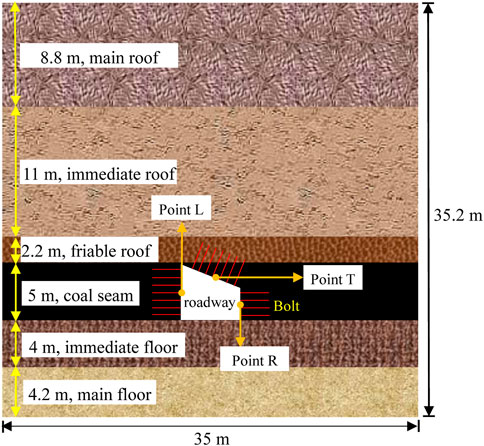
FIGURE 10. Numerical model.
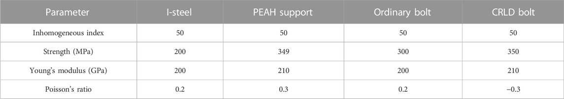
TABLE 2. Mechanical properties of support materials.
Due to the depth of the roadway, the overlying 583.5 m topsoil and rock strata are replaced by uniform loads. If the average self-weight of the rock stratum on the upper part of this numerical model is set as 27 kN/m3, the constant load on the upper part is
4.4 Analysis of support effect of different support schemes
4.4.1 Support resistance analysis
As shown in Figure 11A, the roadway seriously shrinks under the action of external force, and there is a sliding block on the upper part of the high side for the roadway without any support. The numerical simulation results are consistent with the theoretical analysis results, showing the accuracy and reliability of the numerical simulation results.
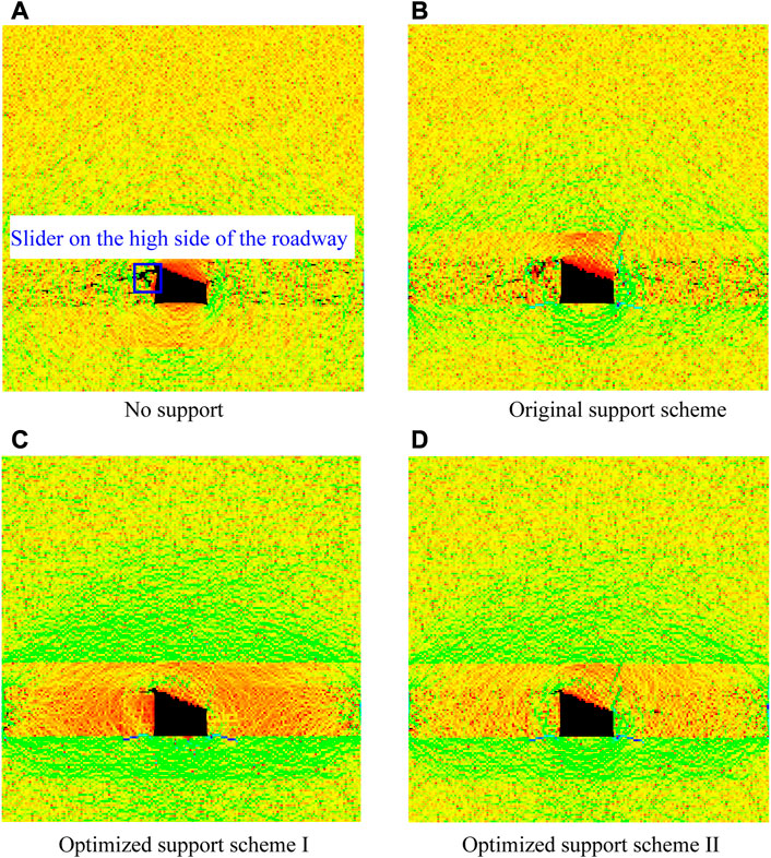
FIGURE 11. Deformation and failure mode of the surrounding rock under various support schemes. (A) No support. (B) Original support scheme. (C) Optimized Support Scheme I. (D) Optimized Support Scheme II.
As shown in Figure 12A, the stress curves of the high and low sides of the roadway in the original support scheme showed a sudden increase and decrease during the loading late stage, and the maximum stresses of the high and low sides are 39.76 MPa and 21.05 MPa, respectively. In addition, the stress of the low side is higher than that of the high side in the whole loading process. These phenomena show that the stress concentration area on the high side of the same roadway section is larger, and the stress concentration degree on the low side is reduced. According to Figure 11B, the roadway has obvious shrinkage and cracks appearing in the surrounding rock of the high side.
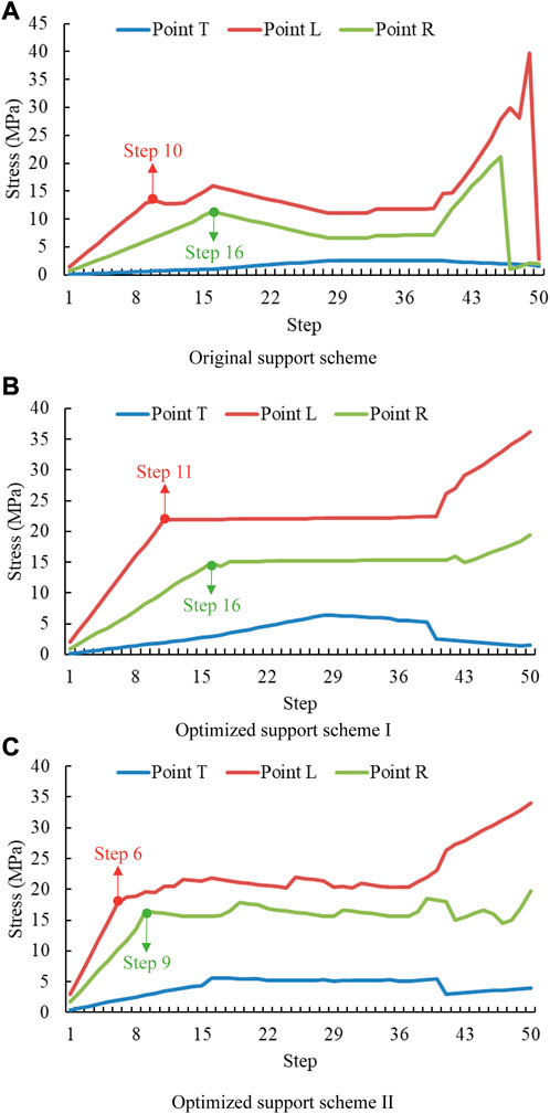
FIGURE 12. Variation trend of surrounding rock stress under various support schemes. (A) Original support scheme (B) Optimized Support Scheme I (C) Optimized Support Scheme II.
As shown in Figure 12B, the stress-loading step curves of points L and R of Optimized Support Scheme I appear to increase significantly in the initial loading stage. The load is mainly borne by the surrounding rock, with the CRLD bolt in the elastic deformation stage. The stress-loading step curves of Points L and R appear and increase again with the increase of load—maximum stress is 36.14 MPa and 19.41 MPa, respectively. The peak stress of the low side is only 53.7% of the high side, the stress difference between the two sides is 16.73 MPa, and the stress distribution of the two sides shows obvious asymmetry. The ordinary I-steel begins to play a role at this time, and the surrounding rock, the CRLD bolt, and the ordinary I-steel bear the load together.
The stress curve slope of the left side is higher than that of the right side in the two rising stages of the stress curve. The stress of the left side is also higher than that of the right side in the horizontal stage of stress curve. The roadway’s left side thus bears greater load and is more prone to damage. Moreover, the stress curves of the left and right sides reach the horizontal stage in the 11th and 16th steps, respectively, and the left side (high side) bolts give play to the bearing capacity before the right side (low side) bolts.
Compared with Points L and R, the stress change of Point T in the Optimized Support Scheme I is relatively gentle, and the maximum stress is only 6.41 MPa. The stress at Point T decreases in the later stage of loading, indicating that the load of the roadway is mainly borne by the left and right sides. Moreover, there is no obvious damage to the roadway surrounding rock, with only a short crack in the upper right corner of the roadway (Figure 11C). This shows that the optimized support scheme of CRLD bolt + ordinary I-steel as the main support can improve the stress state of the rock mass so that the compressive effect of the surrounding rock is obviously better than in the original support scheme.
As shown in Figure 12C, the stress variation trend of Points T, R, and L of Optimized Support Scheme II is roughly the same as that of Optimized Support Scheme I, with the stress fluctuating slightly in the plastic stage. The stress is strengthened at the later stage of loading, and the maximum stress at the three points is 34.02, 19.72, and 5.63 MPa, respectively. The rock surrounding the roadway does not appear to suffer roof fall and rib spalling after the loading. The scheme with EAH support + ordinary bolt as the main support body can resist external force and maintain the integrity of the rock surrounding the roadway (see Figure 11D).
4.4.2 Deformation analysis
As shown in Figure 13, the deformation curves of the roadway roof and the two sides under the original support scheme show three stages of rising–horizontal–rising. This phenomenon shows that the surrounding rock deformation develops continuously into the roadway, thus destroying the integrity of the rock surrounding the roadway. However, the deformation curves of the roadway roof and the two sides of Optimized Support Schemes I and II show two stages of rising–level. This phenomenon shows that the deformation of the rock surrounding the roadway tends to a fixed value with an increase in time, so the deformation control effect of roadway surrounding rock is remarkable.
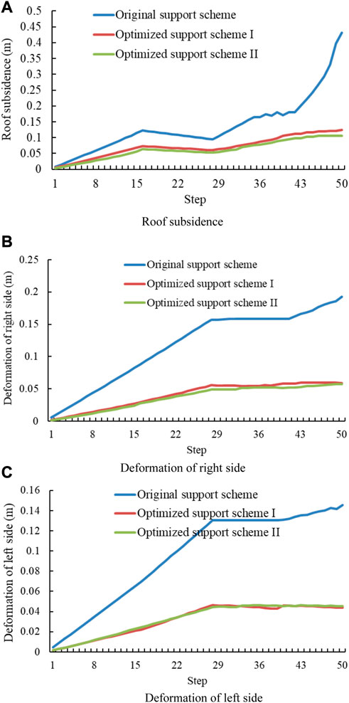
FIGURE 13. Variation trend of surrounding rock deformation under various support schemes. (A) Roof subsidence. (B) Deformation of right side. (C) Deformation of left side.
As shown in Figure 14, no matter what kind of support method is used, the roadway’s left side deformation is relatively large, but the deformation of the roadway’s right side and roof is relatively small. The deformation of the roadway’s high side can reach 0.432 m in the original support scheme. The deformation of the roadway high side in Optimized Support Schemes I and II is reduced to 0.192 m and 0.145 m, respectively, which is 55.6% and 66.4% lower than the original scheme, respectively.
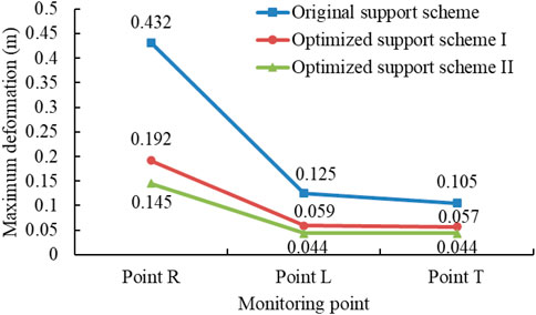
FIGURE 14. Comparison of maximum deformation at different points under various support schemes.
The deformation of the roadway’s low side is 0.125 m in the original support scheme. The deformation of the roadway’s low side in Optimized Support Schemes I and II is reduced to 0.059 m and 0.044 m, respectively, which is 52.8% and 64.8% lower than that of the original scheme, respectively.
The deformation of the roadway’s roof is 0.105 m in the original support scheme. The deformation of the roadway’s low side in Optimized Support Schemes I and II is reduced to 0.057 m and 0.044 m, respectively, which is 45.7% and 58.1% lower than that in the original scheme, respectively.
Optimized Support Scheme II can minimize the deformation of each point of the roadway and maximize the reduction range, which shows that this support method can effectively control the roof separation and roadway side deformation and meet the long-term normal mining requirements of the working face.
4.4.3 AE change trend
Mogi analyzed the AE characteristics of different types of materials and summarized three basic AE types: main shock, foreshock–main shock–aftershock, and swarm shock (Mogi, 1986). It can be seen from Figures 15 and 16 that AE quantity and the energy of the original support scheme belong to the main shock type. AE mainly occurs in the late stage of loading, and the cumulative AE quantity and energy both suddenly increase. The aforementioned phenomena can easily cause damage to the rock mass and support body, indicating that the original support scheme cannot effectively control the deformation of the surrounding rock. The AE quantity and energy of Optimized Support Schemes I and II belong to the swarm shock type. The AE dispersion occurs throughout the loading process, and the AE cumulative quantity and energy both slowly increase. This shows that the Optimized Support Schemes slow the failure rate of the surrounding rock, which will not suddenly release energy to cause support failure.
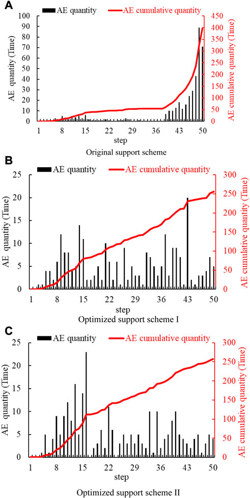
FIGURE 15. Variation trend of the AE quantity under various support schemes. (A) Original support scheme. (B) Optimized Support Scheme I. (C) Optimized Support Scheme II.
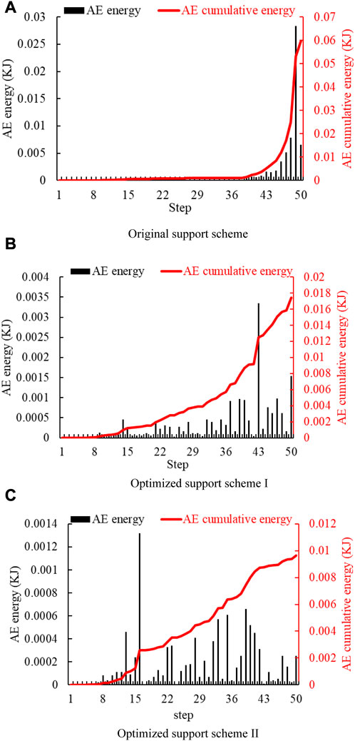
FIGURE 16. Variation trend of AE energy under various support schemes. (A) Original support scheme. (B) Optimized Support Scheme I. (C) Optimized Support Scheme II.
As shown in Figure 17, the AE cumulative and maximum quantity is 396 and 89, respectively, in the original support scheme. After Optimized Support Scheme I is adopted, the AE cumulative and maximum quantity is reduced to 256 and 20, respectively, which is a respective reduction of 35.4% and 77.5% on the original scheme. After Optimized Support Scheme II is adopted, the AE cumulative and maximum quantity is reduced to 257 and 23, respectively, which is a respective reduction of 35.1% and 74.2% on the original scheme.
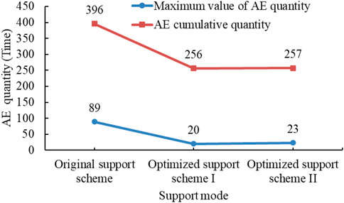
FIGURE 17. Comparison of maximum value of AE quantity under various support schemes.
As shown in Figure 18, the AE cumulative and maximum energy is 0.0598 KJ and 0.02831 KJ, respectively, in the original support scheme. After Optimized Support Scheme I is adopted, the AE cumulative and maximum energy is reduced to 0.01741 KJ and 0.00335 KJ, respectively, which is a respective reduction of 70.9% and 88.2% on the original scheme. After Optimized Support Scheme II is adopted, AE cumulative and maximum energy is reduced to 0.00964 KJ and 0.00132 KJ, respectively, which is a respective reduction of 83.4% and 95.3% on the original scheme.
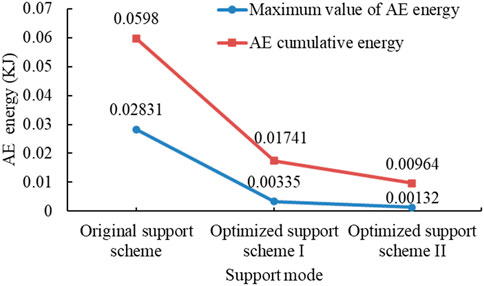
FIGURE 18. Comparison of maximum value of AE energy under various support schemes.
It is thus evident that the AE indicators have decreased significantly through the aforementioned analysis, which indicates that the stability of the rock surrounding the roadway has increased significantly after the optimization schemes were adopted. In particular, Optimized Support Scheme II can maximize the effect of the support system to achieve roadway stability.
5 Conclusion
1. The theoretical analysis results show that the deformation characteristics of right-angled trapezoidal roadways in deep mines are mainly manifested in the asymmetric deformation of the high and low road sides, and the typical failure mode is the upper slip of the high side. The maximum deformation of the surrounding rock from large to small is in the high side, the low side, and the roof. The numerical simulation results are consistent with the theoretical analysis results, demonstrating that the numerical simulation method is feasible for analyzing the problem.
2. The deflection of the inclined roof is directly proportional to the inclination angle. The maximum deflection value occurs in the middle of the roof. This value and inclination can be well-fitted into a quadratic parabola, and R2 is up to 99.9%.
3. The support method of ordinary bolt + I-steel cannot effectively control the deformation and failure of the surrounding rock. According to the actual situation on site, support schemes with CRLD bolt + ordinary I-steel or PEAH support + ordinary bolt as the main support can reduce the deformation of the roadway high side 0.192 m and 0.145 m, respectively; the decline range is 55.6% and 66.4%, which meets the support requirements of deep right-angled trapezoidal roadways.
4. The support schemes with CRLD bolt + ordinary I-steel or PEAH support + ordinary bolt as the main support can slow the AE cumulative quantity and energy increase rate. The released AE type is swarm shock, which ensures that the energy stored in the surrounding rock is slowly and gradually released. Therefore, either of the two aforementioned schemes can ensure the stability and integrity of the rock surrounding roadways.
Data availability statement
The original contributions presented in the study are included in the article/Supplementary material; further inquiries can be directed to the corresponding author.
Author contributions
FC: writing original draft. XW: funding acquisition. XB: review.
Funding
This research was supported by the Chinese National Natural Science Foundation (No. 52074142).
Conflict of interest
The authors declare that the research was conducted in the absence of any commercial or financial relationships that could be construed as a potential conflict of interest.
Publisher’s note
All claims expressed in this article are solely those of the authors and do not necessarily represent those of their affiliated organizations, or those of the publisher, the editors, and the reviewers. Any product that may be evaluated in this article, or claim that may be made by its manufacturer, is not guaranteed or endorsed by the publisher.
References
Cao, C., Ren, T., Cook, C., and Cao, Y. (2014). Analytical approach in optimising selection of rebar bolts in preventing rock bolting failure. Int. J. Rock Mech. Min. Sci. 72, 16–25. doi:10.1016/j.ijrmms.2014.04.026
Chen, X. N., Shen, P., Xiong, X. Y., and Fan, J. W. (2019). Experimental research of asymmetric characteristics of surrounding rock stress in right angle trapezoidal tunnel of inclined coal seam. Coal Technol. 38 (01), 13–15. doi:10.13301/j.cnki.ct.2019.01.005
Chen, X. N., Xiong, X. Y., Wang, J. C., and Shen, P. (2019). Numerical simulation study on asymmetric characteristics of surrounding rock stress in right angle trapezoidal roadway. Coal Sci. Technol. 47 (4), 57–62. doi:10.13199/j.cnki.cst.2019.04.010
Chen, L. X., Kang, H. P., Jiang, P. F., Li, W. Z., Yang, J. W., Zheng, Y, F., et al. (2021). Deformation and failure characteristics and control technology of surrounding rocks in deeply gob-side entry driving. J. Min. Saf. Eng. 38 (2), 227–236. doi:10.13545/j.cnki.jmse.2019.0586
Chen, F., Du, Y. H., Sun, X. M., Ma, T. H., and Tang, C. A. (2021). Numerical experimental study on influence factors of anchoring force of constant resistance bolt. . Geomatics, Nat. Hazards Risk 12 (1), 424–442. doi:10.1080/19475705.2021.1880490
Chen, F., Wang, X. B., Du, Y. H., and Tang, C. A. (2021). Numerical analysis of the precursory information of slope instability process with constant resistance bolt. Sci. Rep. 11 (1), 1–10. doi:10.1038/s41598-021-01387-z
He, M. C., and Guo, Z. B. (2014). Mechanical property and engineering application of anchor bolt with constant resistance and large deformation. Chin. J. Rock Mech. Eng. 31 (7), 1297–1308. doi:10.13722/j.cnki.jrme.2014.07.001
He, M. C., Gong, W. L., Wang, J., Qi, P., Tao, Z., Du, S., et al. (2014). Development of a novel energy-absorbing bolt with extraordinarily large elongation and constant resistance. Int. J. Rock Mech. Min. Sci. 67 (1), 29–42. doi:10.1016/j.ijrmms.2014.01.007
He, M. C., Wang, J., Sun, X. M., and Yang, X. J. (2014). Mechanics characteristics and applications of prevention and control rock bursts of the negative Poisson's ratio effect anchor. J. China Coal Soc. 39 (2), 214–221. doi:10.13225/j.cnki.jccs.2013.2022
Hou, C. J. (2017). A study on the key technologies of controlling the surrounding rock of deep roadway. J. China Univ. Min. Technol. 46 (5), 970–978. doi:10.13247/j.cnki.jcumt.000660
Kang, H. P., Jian, L., and Wu, Y. Z. (2009). Development of high pretensioned and intensive supporting system and its application in coal mine roadways. Procedia Earth Planet. Sci. 1 (1), 479–485. doi:10.1016/j.proeps.2009.09.076
Kang, H. P., Wang, G. F., Jiang, P. F., Wang, J. C., Zhang, N., Jing, H. W., et al. (2018). Conception for strata control and intelligent mining technology in deep coal mines with depth more than 1000 m. J. China Coal Soc. 43 (7), 1789–1800. doi:10.13225/j.cnki.jccs.2018.0634
Kang, H. P., Jiang, P. F., Huang, B. X., Guan, X. M., Wang, Z. G., Wu, Y. Z., et al. (2020). Roadway strata control technology by means of bolting-modification-destressing in synergy in 1000 m deep coal mines. J. China Coal Soc. 45 (3), 845–864. doi:10.13225/j.cnki.jccs.SJ20.0204
Kang, H. P. (2021). Seventy years development and prospects of strata control technologies for coal mine roadways in China. Chin. J. Rock Mech. Eng. 40 (1), 1–30. doi:10.13722/j.cnki.jrme.2020.0072
Le, T. D., Mitra, R., Oh, J., and Hebblewhite, B. (2017). A review of cavability evaluation in longwall top coal caving. Int. J. Min. Sci. Technol. 27 (6), 907–915. doi:10.1016/j.ijmst.2017.06.021
Li, C., He, M. C., and Gong, W. L. (2016). Interventional nanotheranostics of pancreatic ductal adenocarcinoma. J. China Coal Soc. 41 (6), 1393–1402. doi:10.7150/thno.15122
Ma, J. Y., Zhang, L., Tu, S. H., Tu, H. S., Liu, X., and Miao, K. J. (2022). Deformation and failure law and control technology of right-angle trapezoidal mining roadway in deep mine. J. Min. Saf. Eng. 40 (1), 82–90. doi:10.13545/j.cnki.jmse.2021.0588
Mogi, K. (1986). Recent earthquake prediction research in Japan. Science 233 (4761), 324–330. doi:10.1126/science.233.4761.324
Pan, Y. S., Qi, Q. X., Wang, A. W., Xiao, Y. H., Chen, J. Q., Lv, X. F., et al. (2020). Theory and technology of three levels support in bump-prone roadway. J. China Coal Soc. 45 (5), 1585–1594. doi:10.13225/j.cnki.jccs.DY20.0261
Pan, Y. S., Xiao, Y. H., and Li, G. Z. (2020). Roadway hydraulic support for rockburst prevention in coal mine and its application. J. China Coal Soc. 45 (1), 90–99. doi:10.13225/j.cnki.jccs.YG19.1762
Su, X. G., Song, X. M., Li, H. C., Yuan, H. H., Li, B. K., and Du, X. J. (2016). Study on roadway damage characteristics and stability control of extra-thick inclined compound roof. J. Min. Saf. Eng. 33 (2), 244–252. doi:10.13545/j.cnki.jmse.2016.02.009
Tang, C. A., and Kaiser, P. K. (1998). Numerical simulation of cumulative damage and seismic energy release during brittle rock failure—Part I: Fundamentals. Int. J. Rock Mech. Min. Sci. 35 (2), 113–121. doi:10.1016/s0148-9062(97)00009-0
Tang, C. A., Wang, S. H., and Fu, Y. F. (2003). Numerical test on rock failure process. Beijing: Science Press.
Tang, C. A. (1997). Numerical simulation of progressive rock failure and associated seismicity. Int. J. Rock Mech. Min. Sci. 34 (2), 249–261. doi:10.1016/s0148-9062(96)00039-3
Wang, J., Yu, B., Kang, H., Wang, G., Mao, D., Liang, Y., et al. (2015). Key technologies and equipment for a fully mechanized top-coal caving operation with a large mining height at ultra-thick coal seams. Int. J. Coal Sci. Technol. 2 (2), 97–161. doi:10.1007/s40789-015-0071-4
Wang, W. J., Yuan, C., Yu, W. J., Wu, H., Peng, W. Q., Peng, G., et al. (2016). Stability control method of surrounding rock in deep roadway with large deformation. J. China Coal Soc. 41 (12), 2921–2931. doi:10.13225/j.cnki.jccs.2016.1115
Wang, X. F., Wang, Y., and Zhang, D. S. (2017). Enhanced support technology for key area of the roadway in large inclined angle “three-soft” coal seam. J. Min. Saf. Eng. 34 (2), 208–213. doi:10.13545/j.cnki.jmse.2017.02.002
Wang, Q., He, M. C., Yang, J., Gao, H., Jiang, B., and Yu, H. (2018). Study of a no-pillar mining technique with automatically formed gob-side entry retaining for longwall mining in coal mines. Int. J. Rock Mech. Min. Sci. 110, 1–8. doi:10.1016/j.ijrmms.2018.07.005
Wang, G. F., Zhang, J. H., Xu, Y. J., Ren, H. W., Yu, X., Liu, X. H., et al. (2021). Supporting stress characteristics and zonal cooperative control technology of long working face in deep thick coal seam. J. China Coal Soc. 46 (3), 763–773. doi:10.13225/j.cnki.jccs.yt20.1971
Wu, N., Liang, Z. Z., Zhang, Z. H., Li, S. H., and Lang, Y. X. (2022). Development and verification of three-dimensional equivalent discrete fracture network modelling based on the finite element method. Eng. Geol. 306 (5), 106759. doi:10.1016/j.enggeo.2022.106759
Xie, W. B., Jing, S. G., Wang, T., Ren, Y. K., and Zhang, N. (2010). Structural stability of U-steel support and its control technology. Chin. J. Rock Mech. Eng. 29 (2), 3743–3748.
Xiong, X. Y., and Dai, Jun (2020). Research on support technology of right angle trapezoidal roadway in generally inclined coal seam. J. China Coal Soc. 45 (S1), 110–118. doi:10.13225/j.cnki.jccs.2019.1086
Yang, S., Zhang, J., Chen, Y., and Song, Z. (2016). Effect of upward angle on the drawing mechanism in longwall top-coal caving mining. Int. J. Rock Mech. Min. Sci. 85, 92–101. doi:10.1016/j.ijrmms.2016.03.004
Zhang, N., and Gao, M. S. (2002). High-strength and pretension bolting support of coal roadway and its application. J. China Univ. Min. Technol. 33 (5), 524–527.
Keywords: right-angled trapezoidal roadway, asymmetric deformation, support, surrounding rock control, stress
Citation: Chen F, Wang X and Bai X (2023) Study of deformation law and support design feasibility of right-angled trapezoidal roadways. Front. Earth Sci. 11:1103498. doi: 10.3389/feart.2023.1103498
Received: 20 November 2022; Accepted: 24 March 2023;
Published: 19 April 2023.
Edited by:
Qingsheng Bai, Freiberg University of Mining and Technology, GermanyReviewed by:
Yunliang Tan, Shandong Univeristy of Science and Technology, Qingdao, ChinaPin Wang, Central South University, China
Qidong Gao, Chang’an University, China
Copyright © 2023 Chen, Wang and Bai. This is an open-access article distributed under the terms of the Creative Commons Attribution License (CC BY). The use, distribution or reproduction in other forums is permitted, provided the original author(s) and the copyright owner(s) are credited and that the original publication in this journal is cited, in accordance with accepted academic practice. No use, distribution or reproduction is permitted which does not comply with these terms.
*Correspondence: Feng Chen, Y2ZsdWNreUBzaW5hLmNu