- 1China Three Gorges Construction Engineering Corporation, Chengdu, China
- 2State Key Laboratory of Geomechanics and Geotechnical Engineering, Institute of Rock and Soil Mechanics, Chinese Academy of Sciences, Wuhan, China
- 3Key Laboratory of Ministry of Education on Safe Mining of Deep Metal Mines, Northeastern University, Shenyang, China
- 4Hubei Province Key Laboratory Processing of Mineral Resources and Environment, Wuhan University of Technology, Wuhan, China
- 5China Three Gorges Corporation, Wuhan, China
- 6Sinohydro Bureau 6 Co. Ltd, Shenyang, China
The underground powerhouse of China’s Wudongde hydropower station is one of the world’s underground powerhouses with the largest span and height. Because the underground powerhouse is all located in steeply-inclined layered rock masses, and the bedding plane strike of the rock mass has a small angle with the axis of the main caverns, there is a serious risk of high sidewall instability. According to the basic principles of the structurally-controlled concept, the mechanical properties of bedding planes and other discontinuities are largely attributed to this problem. A thorough investigation was conducted into the Wudongde underground powerhouse throughout the excavation process to clarify the possible mechanisms behind these failures and to realize the dynamic adjustment of construction. First, the geological conditions and mechanical properties of the rock masses in the study area were introduced in detail. The stability of the right bank underground powerhouse’s surrounding layered rock mass was then investigated using a discontinuum-based numerical method. Special attention was paid to the excavation-induced failure mechanisms of the steeply-inclined small-angle layered rock masses at the upstream high sidewall. The results show that the failure of steeply-inclined small-angle layered surrounding rock masses presents significant three-stage characteristics, i.e., 1) rock plate forms due to the unloading opening of the bedding plane; 2) rock plate cracks due to bending; and 3) rock plate buckles or slides due to crack penetration. Based on the understanding of the deformation and failure mechanisms of steeply-inclined small-angle layered rock masses, the excavation sequence needs to be optimized according to local geological conditions. In practice, it is vital to insist on the principles of excavation by thin layers and finish all the supports before the next-step excavation.
Introduction
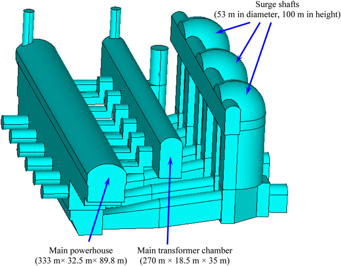
As part of one of China’s largest multipurpose water conservation projects, a hydropower station is being constructed downstream of the Jinsha River at Wudongde town. The Wudongde hydropower station consists of three parts: an underground powerhouse, a dam, and a navigation facility. The underground powerhouse covers both sides of the river in the downstream direction. The Wudongde underground powerhouse has the main powerhouse (333 m long, 30.5–32.5 m wide, and 89.8 m high), a transformation chamber (270 m × 18.5 m × 35 m), and three surge shafts (53 m in diameter, 100 m in height) (Figure 1). The main powerhouse is the largest underground main powerhouse in the hydropower industry in terms of height and span. The large-span high-sidewall underground powerhouse is excavated in steeply-inclined layered rock masses, with the bedding plane strike of the rock mass having a small angle (less than 30°) with the main powerhouse’s axis. Therefore, knowing the mechanical response of steeply-inclined small-angle layered rock masses under excavation unloading is crucial to the success of the Wudongde underground powerhouse construction.
The excavation-induced response of rock masses is considered a stability problem of surrounding rock masses in underground engineering. A large amount of excavation generally induces substantial disturbance to the surrounding rock mass, leading to different kinds of engineering geological problems. Under low-moderate geostress, structurally-controlled instabilities are the primary form (Fekete and Diederichs, 2013), while stress-related issues are often encountered in deep-buried caverns (Diederichs et al., 2004; Martin and Christiansson, 2009; Cai and Kaiser, 2014). The rock mass structure; however, is undoubtedly one of the most salient factors influencing the stability of a large underground powerhouse.
Bedding planes, like other structural plane systems, introduce significant anisotropy both in deformation pattern as well as strength (Fortsakis et al., 2012). The places with more displacements and failures are closely related to the spatial relationship between cavern axes and bedding plane strikes (Zhou Y.-Y. et al., 2016; Zhou YY. et al., 2016). For example, typical geomechanical issues of underground powerhouses excavated in steeply-inclined layered rock masses are primarily the excessive deformation of high straight sidewalls. Failure mechanisms of steeply-inclined small-angle layered surrounding rock masses, however, become more complicated than massive, almost isotropic rock masses due to the presence of bedding planes. Combined failure types, such as tensile fractures through rocks plus shearing along bedding planes, are more commonly observed. Therefore, the bedding plane-induced discontinuous and anisotropic nature (Singh, 1973; Amadei and Pan, 1992; Marinos and Hoek, 2000; Xiao and Wang, 2002; Zhang and Liu, 2002; ZhanG et al., 2004; Wu et al., 2006; Zhang, 2006; Peng et al., 2007; Zhu et al., 2009; Fan and Wang, 2011) is critical to analyzing the stability of layered surrounding rock masses. This also indicates that successful pertinent support for layered surrounding rock masses should be used as an improved means to eliminate the negative impact of steeply-inclined bedding planes. In such a case, it is an important issue to evaluate the stability of steeply-inclined layered surrounding rock masses with or without support during the construction of a large-span high-sidewall underground powerhouse within these rock masses.
In this paper, the stability of the steeply-inclined small-angle layered surrounding rock masses at the upstream high sidewall of the Wudongde right main powerhouse is investigated using the discrete element method (DEM). The study mainly focuses on the excavation-induced failure mechanisms of the steeply-inclined small-angle layered surrounding rock masses at the upstream high sidewall between the seven# and eight# generator sections. Some suggestions for optimizing the excavation scheme and supporting measures are proposed. It is hoped that this case study will be of practical significance to other large-scale excavations with similar geological conditions.
Engineering Background
Geological Setting
The geological map of the Wudongde underground powerhouse on the right bank at an elevation of 850 m is demonstrated in Figure 2. The whole underground powerhouse on the right bank is situated in steeply-dipping layered carbonate rock masses belonging to the meso-proterozoic eon (
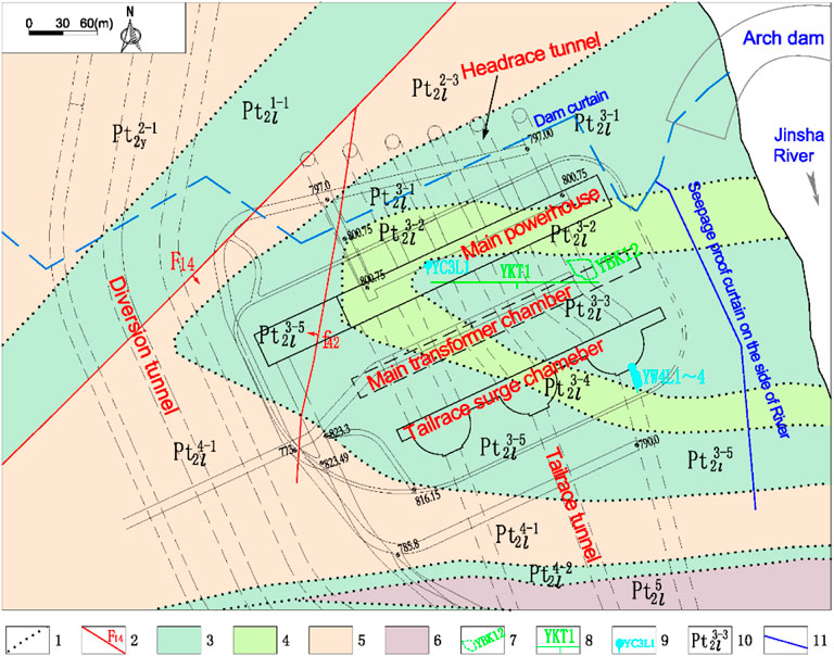
FIGURE 2. Geological map of the underground powerhouse on the right bank at EL800 m (1) stratigraphic boundary, (2) fault, (3) moderate karst rock formation, (4) weak karst rock formation, (5) slight karst rock formation, (6) non-karst rock formation, (7) karst cave, (8) corrosion discontinuity, (9) spring, (10) strata code, (11) curtain.
There are no large-scale faults in the areas of underground powerhouse. Only five small-scale faults of several meters in length and several centimeters in width have been identified. There is a fold whose axial plane is also steeply dipping and oblique to cavern axes in the area of right underground powerhouse. The core stratum of the fold is made up of
Excavation, Support, and Monitoring Plan
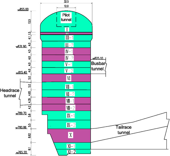
The powerhouse on the right bank was constructed in January 2013 and is designed to be excavated in 11 layers (Figure 4). Systematic supports for the powerhouse are comprised of rock bolts, prestressed cables, shotcrete with wire mesh, etc. Detailed support parameters are summarized in Table 1. At the beginning of June 2015, the excavation of Layer V and systematic support were finished.
For the underground powerhouse, eight systematic monitoring cross-sections are chosen, including the central line of each generator as well as the main and auxiliary erection bays. The primary monitoring items are the displacements of surrounding rocks at different depths, stresses and forces in supports, and crane girders deformations. The pre-embedded multipoint extensometers are arranged around a typical monitoring cross-section in the roof, crane girder, and sidewalls on both sides. Rock bolt stress meters and anchor cable dynamometers are fixed to rock bolts or cables to record variations of stresses or forces, which are installed after excavation. The layout of the monitoring devices around a cross-section is shown in Figure 5.
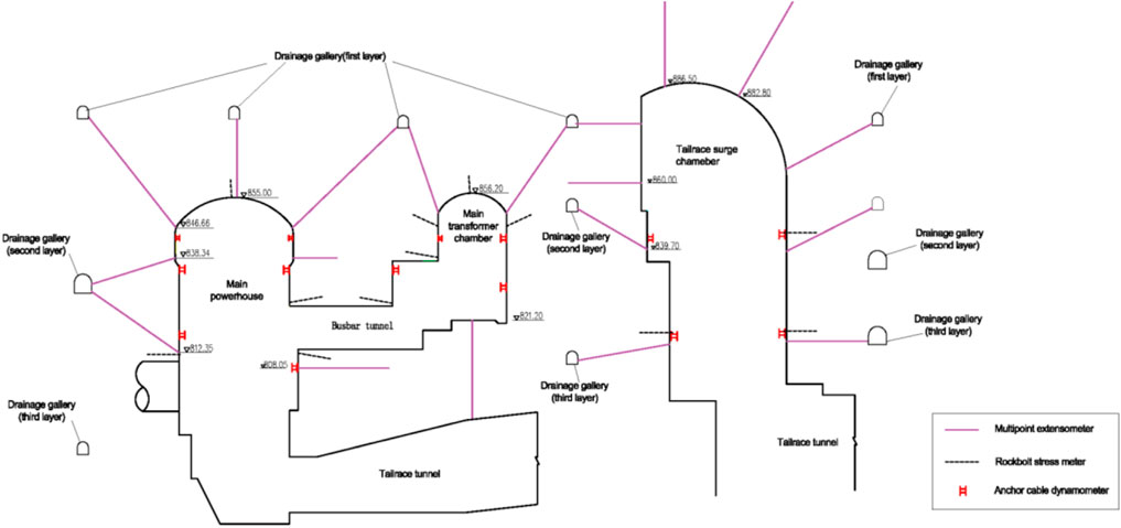
FIGURE 5. Layout of the monitoring devices instrumented for one of the cross-sections of the underground powerhouse.
Characteristics of Layered Rock Masses
The macroscopic behavior of a layered rock mass is generally determined by its components, that is, interlayered rocks and bedding planes. The mechanical behavior tests of layered or foliated rocks (Nasseri et al., 2003; Hakala et al., 2007; Cho et al., 2012) show that the directionality of deformation and strength are the most significant characteristics of these rocks. It is generally accepted that deformation perpendicular to the bedding plane is more pronounced than that parallel to the bedding plane. Therefore, greater deformation in the field is more likely to occur in the direction perpendicular to the bedding plane. In addition, normal joint stiffness is sensitive to changes in normal stress (Bandis et al., 1983) and decreases nonlinearly when unloaded. As a result, the bedding plane deformation can reach an acceleration phase gradually. When exposed to or experiencing environmental changes, various bedding planes, especially those with clay fill, may exhibit time-dependent behavior. Natural surface conditions of bedding planes typically exhibit mineral coatings and suffer from various degrees of weathering, which can significantly reduce bond strength compared with unweathered and cemented discontinuities. Based on these observations, it is reasonable to believe that layered rock mass provides the possibility of more deformation perpendicular to bedding and bedding plane opening when the surrounding constraints are suddenly reduced to a negligible level (Xu et al., 2017). Moreover, the spatial continuity of bedding planes provides another possibility that, once part of the bedding plane is kinematically admissible, it tends to move as a whole, resulting in an expansion of the fracture area. The last special feature of this rock mass that needs to be noted is that the plate shape of each layer makes it easier to bend than other massive or jointed rock masses (Zhou et al., 2017). Therefore, proper consideration of the distribution laws and mechanical properties of bedding planes in numerical simulations is the premise of reasonable analysis based on field geological analysis.
Discontinuum Analysis of the Failure Mechanisms of Steeply-Inclined Small-Angle Layered Surrounding Rock Masses
Model and Parameters
In light of the anisotropic and discontinuous nature of layered rock masses, the excavation of the right bank powerhouse is simulated using the discrete element software 3DEC (Itasca Consulting Group and Inc, 2007). According to previous descriptions, the bedding plane strike of the steeply-inclined layered rock mass of the upstream sidewall between the seven# and eight# generator sections has a small angle with the main powerhouse’s axis. Furthermore, the bedding planes are inclined toward the interior of the powerhouse, which is unfavorable to the stability of the sidewalls after the excavation. Considering these conditions, all the rock mass of the seven# generator unit and part of the rock mass of the eight# generator unit are incorporated into the numerical model, and the stability of surrounding rock masses in these areas is particularly concerned in the simulation.
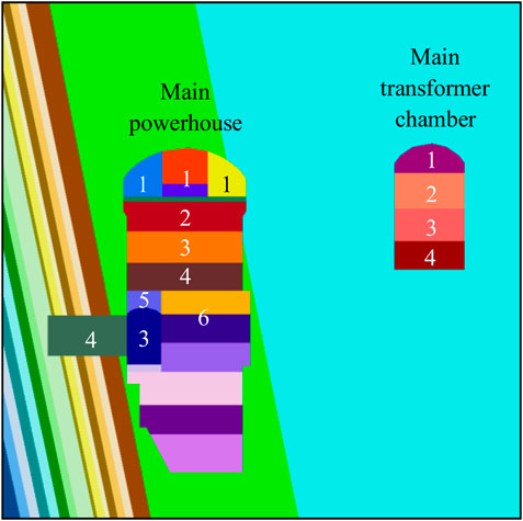
The numerical model includes the mountain, surrounding rock masses, and caverns (Figure 6). The total length of the model along the cavern axis is 82 m, and the maximum buried depth of the top arch of the main powerhouse is 286 m. To simulate the structure of steeply-inclined small-angle layered surrounding rock masses at the upstream sidewall, the rock masses are divided into layers with a thickness of 2 m. The angle between the bedding plane strike and the cavern axis is 14°, and the dip angle is 79°. There are 638,857 nodes and 257,041 elements in the model.
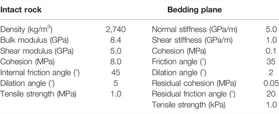
The in situ stress field is generated according to the investigation reports provided by relevant geological departments. Self-weight stress is applied as the maximum principal stress. The lateral pressure coefficients along and normal to the cavern axis are 0.8 and 0.6, respectively. The upper surface of the model is a free boundary, while normal constraints are applied to the rest of the surfaces. The internal unbalanced forces of rocks and bedding planes are calculated to equilibrium using the elastic constitutive model, and the equilibrium convergence value is 1 × 10⁻⁴. The input parameters of the model are shown in Table 2.
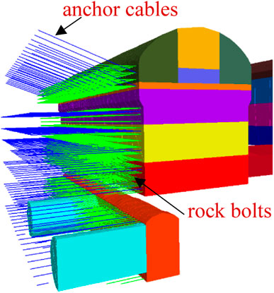
In the numerical simulations, the Mohr‒Coulomb strength criterion is used for rocks, and the Coulomb strength criterion with residual strengths is adopted for bedding planes. Mechanical parameters of rock masses provided by geological departments are employed as input parameters (Table 3). Cable elements are used to simulate the reinforcement effects of the pertinent supports (systematic rock bolts and anchor cables) on the steeply-inclined small-angle layered surrounding rock masses at the upstream sidewall under supported condition. The input parameters for the systematic support are demonstrated in Table 4.
Protocol
The simulation is performed under supported and non-supported conditions. After excavation, the system supports are applied to the upstream sidewall in the corresponding elevation ranges, and the excavation sequence is simulated by the actual excavation, as shown in Figure 6. The support forms are demonstrated in Figure 7. Because the tailrace surge chambers are far from the main powerhouse, their excavation influence on the stability of the surrounding rock masses of the main powerhouse can be negligible. Therefore, the numerical model does not include the excavations of the tailrace surge chambers. The equilibrium convergence value is 1 × 10⁻⁴. The specific steps are shown as follows.
Step 1: Layers I of the main powerhouse and the main transformer chamber are excavated.
Step 2: Layers II and III of the main powerhouse and Layer II of the main transformer chamber are excavated, as well as the busbar tunnel and the outlet shaft.
Step 3: Layer IV of the main powerhouse, Layer III of the main transformer chamber, and the L3 tunnel are excavated.
Step 4: Layer V of the main powerhouse, Layer IV of the main transformer chamber, and the headrace tunnels are excavated.
Step 5: The top layer of the L3 tunnel of the main powerhouse is removed.
Step 6: Layers VI and VII of the main powerhouse are excavated.
L3 tunnel (9 m × 11–15 m) is pre-excavated in the lower part of the main powerhouse to excavate the headrace tunnel. After excavating Layer V, the thickness of the overburdened rocks on the top of the L3 tunnel is 2.7–7.6 m.
Results and Discussion
Under non-supported conditions, the deformation fields of surrounding rock masses and failure characteristics of bedding planes after Steps one to four are shown in Figures 8,9.
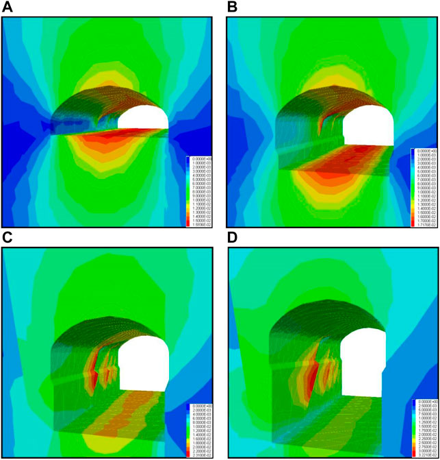
FIGURE 8. Deformation distribution of surrounding rock masses at the upstream sidewall after sequential excavations under nonsupported conditions (Unit: m). (A) step 1, (B) step 2, (C) step 3, and (D) step 4.
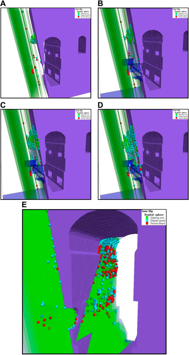
FIGURE 9. Failure characteristics of surrounding rocks on upstream sidewall after sequential excavations under unsupported condition. (A) step 1, (B) step 2, (C) step 3, (D) step 4, (E) front view after step 4. Red ball-tensile failure, blue ball-shear failure in previous steps, green ball-current shear failure.
Based on the distribution characteristics of deformation of surrounding rock masses, after step 1, the largest deformation occurs in the central line of the top arch and the floor (Figure 8). The location of maximum deformation gradually transfers to the steeply-inclined bedding planes and occurs on the bedding planes of the upstream sidewall after Steps two to four as the bench excavation proceeds. After Step 4, the largest deformation reaches 32 mm.
As shown in Figure 9, the tensile failure mode of bedding planes near the excavation boundary is mainly the unloading and opening of bedding planes. Furthermore, tensile failure occurs in the intact rocks, producing tensile cracks. The failure mode of the bedding planes inside the surrounding rock masses is dominated by shear failure, and the maximum depth where shear failure takes place gradually increases with excavation. The failure of bedding planes extends to the interior of the surrounding rock masses, activating internal bedding planes, causing certain shear slip in the surrounding rock masses, and also increasing the slipping area of a single bedding plane. This indicates that the influence of steeply-inclined small-angle layered rock masses on the stability of the main powerhouse’s upstream sidewall gradually increases with excavation.
Table 5 shows the maximum deformation of surrounding rock masses and their corresponding locations under supported and non-supported conditions. Compared with that under non-supported conditions, systematic support can reduce the maximum deformation of surrounding rock masses to some extent. In particular, when large deformations such as unloading openings and shear slip along bedding planes occur, the supports of systematic rock bolts can fully reinforce surface rocks, while anchor cables can inhibit the deformation of the interior bedding planes, as demonstrated in Figure 10. The main differences between rock bolts and anchor cables are their effective anchor length and loading capacity. Rock bolts are usually shorter than anchor cables, and have lower ultimate tensile strength and smaller pretension value. Therefore anchor cables can restrain failure of discontinuities deep inside rock mass, while rock bolts are mainly used to reinforce shallow rock mass.
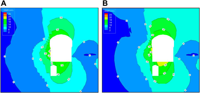
FIGURE 10. Contour plot of the deformation distribution after step 4 excavation under the supported and unsupported conditions (Unit: mm). (A) non-supported condition, (B) systematic support condition.
Tables 6,7 demonstrate the failure indices of rock masses after each step in sequential excavations under non-supported conditions. Shear failure hardly ever happens inside the rocks, and almost all failures are exhibited as tensile failure under low-stress conditions. By comparing failure indices of surrounding rock masses after each step under the two conditions, it is concluded that systematic supports are effective in restraining tensile failure, while the inhibition effects on shear failures are limited. The reason is that systematic supports can bear axial tension and provide partial shear-resisting capacity. However, software built-in cable element mainly considers the axial force characteristics of support but cannot take the shear-resisting function into account. This explains the differences between numerical simulation and actual situations. For the sake of inhibiting their separation during construction, the rock bolts are designed to be approximately normal to the bedding planes. However, by theoretical and experimental results in the literature (Ge and Liu, 1988; Pellet and Egger, 1996), rock bolts strictly normal to the bedding planes cannot sufficiently play their roles in shear-resisting. Therefore, in actual situations, rock bolts, and cables are combined to inhibit the deformation and failure in the direction normal to bedding planes. Since systematic rock bolts are usually installed evenly around the tunnel, in different positions the angle between rock bolt and bedding plane must be different. In order to make full use of rock bolts and anchor cables in the case of sub-vertical bedding plane reinforcement, angles between bedding plane and these structural elements should be adjusted locally. More specifically, at the high sidewalls where bedding planes are more likely to separate or slip, the structural elements should form an optimized angle to the local bedding plane, depending on the predicted failure mode. If tensile failure is anticipated, reinforcements should be as perpendicular to bedding plane as possible, while for the slip failure case, an angle which can fully mobilize the shear resistance of rock bolts should be considered.
The influences of steeply-inclined small-angle layered surrounding rock masses on the upstream sidewall’s stability are mainly reflected by the mechanical responses of original bedding planes in rock masses based on the numerical simulations. Either obvious deformation or failures on the surface and inside rock masses appear at bedding planes. Failed zones of bedding planes gradually increase with the sequential excavation. The characteristics of steeply-inclined small-angle layered surrounding rock masses are that, due to the unloading of normal stresses after excavation together with the anisotropy of rock mass deformation, the deformation of high sidewalls of the rock masses under this condition is more obvious than that of rock masses under other orientation conditions. This is particularly unacceptable for construction safety. Systematic support shows significant inhibiting effects on the separation and failure of bedding planes. However, to fully use the shear-resisting capacity of systematic supports, it is required to further investigate and optimize the layout of rock bolts and cables.
Figure 11 shows the schematic view of the failure mechanisms of the steeply-inclined small-angle layered surrounding rock masses in the right main powerhouse. As the profile of the main powerhouse is high and narrow, with a height of 90 m and a ratio of height to the span of close to three, the unexcavated rock masses can provide sufficient support for both sidewalls, thus constraining the deformation of the sidewalls. Layered excavation gradually reduces the supporting effect of the remaining rock masses. The failure of steeply-inclined small-angle layered surrounding rock masses presents significant three-stage characteristics during these excavations. 1) Bedding planes open due to large-scale excavation unloading, which makes the steeply-inclined small-angle layered surrounding rock masses form a plate-type structure. 2) High tangential stress inside the sidewall induced by stress redistribution leads to the bending of rock plates with fixed ends, resulting in a large number of cracks. 3) Rock plates with cracks buckle or slide due to their insufficient bending strength under the longitudinal load at the plate ends.
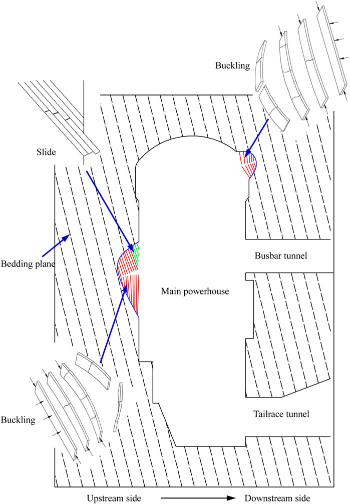
FIGURE 11. Schematic view of the deformation and failure mechanisms of the steeply inclined small-angle layered rock mass in the right bank powerhouse.
Reinforcement Practice and Validation Verification
Based on the abovementioned deformation and failure mechanisms of the steeply-inclined small-angle layered surrounding rock masses of the main powerhouse, excavation and support measures were optimized for these rock masses to reinforce the overall stability of the high sidewalls.
Optimization of Excavation Method and Sequence
Firstly, the heights of excavated layers in corresponding cavern sections were strictly controlled. A large layer was generally excavated into two sublayers with a height of 4‒5 m. In this way, stress inside the surrounding rock masses of sidewalls was slowly unloaded to avoid violent stress redistribution.
Secondly, each layer was excavated by the first middle groove and then protective layers. The middle groove and the protective layers were excavated through small gradient blasting and smooth blasting, respectively. Hereinafter, the unloading degree of surrounding rock masses of sidewalls for each blasting was further reduced, and the protective layers were able to provide certain lateral constraints for convergence deformation of sidewalls and decrease the damage of rock masses of sidewalls caused by blasting.
Finally, blasting parameters were optimized. The maximum explosive charge of each blasting was controlled by 20 kg. The row space and the diameter of blasting holes for excavating medium grooves were 3 m × 2.5 m and 90 mm, respectively. Moreover, the distance between perimeter holes, the diameter of cushion holes, the interval, and the diameter of blasting holes for excavating the protective layers through smooth blasting was 50 cm, 120 cm, 180 cm, and 42 mm, respectively. Controlled blasting can not only effectively decrease the damage degree of intact rocks, but also reduce vibration disturbance to other excavated parts, especially positions with unstable blocks.
Optimization of Support Design
Support optimization includes optimizing support installation time and parameters. As for installation time, according to the deformation characteristics of hard rocks after excavation, supports needed to be finished on time. Random rock bolts and shotcrete with wire mesh were required to be finished as soon as possible to control the unloading and relaxation of surface rocks, and then systematic rock bolts and cables were installed after excavation. Random supports were performed next to the working face immediately after excavation, while systematic supports were generally performed after the working face within 15 m. After excavation, the support with anchor cables was required to be finished within 1 month. As to support parameters, the angles of rock bolts were adjusted by the orientation of rock strata. The aim is to provide certain normal constraints for bedding planes to inhibit opening. Prestressed rock bolts of 9 m long with 50 kN of pretension forces were utilized to substitute the original fully grouted rock bolts applied in regions with small angles between the strike of rock strata and the cavern axis, while row space between anchor cables was adjusted to 3 m × 4.5 m.
Implementation Effect Verification
By 1 May 2015, Layer V of the main powerhouse had been excavated. The monitoring data obtained by the multipoint extensometers in the upstream sidewall and rock crane girder in the section of 7# and 8# generator units is shown in Figure 12. After excavating Layer V, the accumulated deformations of the surrounding rock masses are within 20 mm. Similar to the monitoring results (Wei et al., 2010; Fan et al., 2011) of other underground powerhouses, the displacement-time curve exhibits a stepwise shape: the displacement of surrounding rock masses significantly increases in a short time and gradually stabilizes after excavating each layer. The plateau of the curves shows that the current deformation of the surrounding rock masses is convergent.
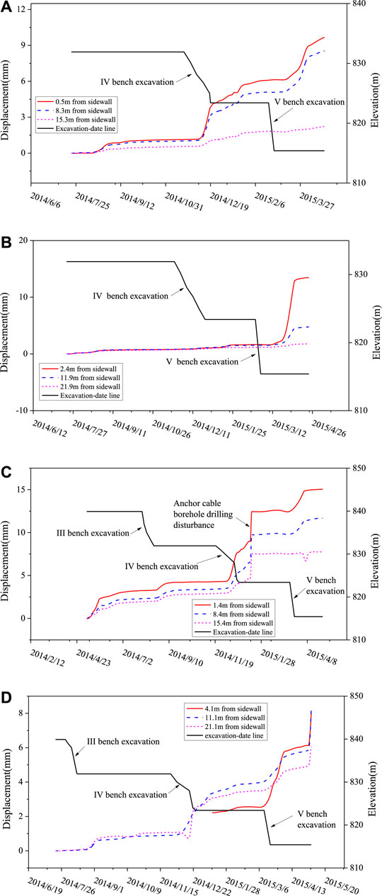
FIGURE 12. Results of the multi-point extensometers at the crane girder and upstream sidewall of the 7# and 8# generator sections. (A) M15Y07 (7# generator, upstream sidewall, EL838.36), (B) M16Y07 (7# generator, upstream sidewall, EL812.35), (C) M06Y08 (8# generator, upstream sidewall, EL838.36), (D) M07Y08 (8# generator, upstream sidewall, EL812.35)
From the monitoring data, it can be seen that the displacement increments of surrounding rock masses induced by the excavation of each layer within the 7# and 8# generator units were generally within 5 mm. Compared with the accumulated deformations in other generator units whose strata do not form a small angle with the cavern axis, it can be found that the deformations in small-angle sections are usually larger. This indicates that the angle between the bedding plane strike and the main powerhouse’s axis is one of the controlling factors affecting the displacement and stability of sidewalls. Both the accumulated displacement values and the characteristics of curves demonstrate that the adopted excavation and support measures show desirable effects on the deformation and failure of high sidewalls.
Conclusion
The failure mechanisms of steeply-inclined small-angle layered surrounding rock masses at the upstream high sidewall during excavation in this study were first investigated using DEM. After excavation, the optimized excavation schemes and supporting measures for the steeply-inclined small-angle layered surrounding rock masses were then proposed to reinforce the overall stability of the high sidewalls. The main conclusions can be drawn as follows:
1) While shear failure is the most significant failure mode in deep regions, the failure of bedding planes close to the excavation boundary is dominated by tensile failure. With the increase in the exposed height of sidewalls, the failure range and depth of bedding planes also increase.
2) The failure of steeply-inclined small-angle layered surrounding rock masses presents significant three-stage characteristics, that is, 1) rock plate forms due to the unloading opening of bedding plane; 2) rock plate cracks due to bending, and 3) rock plate buckles or slides due to crack penetration.
3) The stability of steeply-inclined small-angle layered surrounding rock masses is largely attributed to the mechanical properties of bedding planes. Therefore, the spatial distribution of the main bedding planes needs to be first explored when the underground caverns are planned to be constructed in layered rock masses. Using discontinue mechanics, the rock masses are better treated as a discontinuous medium. The construction processes should be optimized by local geological conditions. Furthermore, it is suggested to insist on the principles of excavation by thin layers and accomplish all the supports before the next-step excavation.
Data Availability Statement
The original contributions presented in the study are included in the article/Supplementary Material, further inquiries can be directed to the corresponding author
Author Contributions
C-LJ: Methodology, Writing- Original draft preparation. D-PX: Conceptualization, Methodology, Writing- Reviewing and Editing. Y-YZ: Discontinuum analysis. D-FC: Investigation. S-WZ: Data curation. L-XH: Investigation. CW: Data curation.
Funding
The authors gratefully acknowledge financial support from the National Natural Science Foundation of China (Nos. 52079027 and 51709043), the Open Research Fund of State Key Laboratory of Geomechanics and Geotechnical Engineering, Institute of Rock and Soil Mechanics, Chinese Academy of Sciences (NO. Z019007).
Conflict of Interest
Author C-LJ is employed by the company China Three Gorges Construction Engineering Corporation. Author L-XH and S-WZ are employed by the company China Three Gorges Corporation. Authors CW and S-LJ are employed by the company Sinohydro Bureau 6 Co. Ltd.
The remaining authors declare that the research was conducted in the absence of any commercial or financial relationships that could be construed as a potential conflict of interest.
Publisher’s Note
All claims expressed in this article are solely those of the authors and do not necessarily represent those of their affiliated organizations, or those of the publisher, the editors and the reviewers. Any product that may be evaluated in this article, or claim that may be made by its manufacturer, is not guaranteed or endorsed by the publisher.
References
Amadei, B., and Pan, E. (1992). Gravitational Stresses in Anisotropic Rock Masses with Inclined Strata. Int. J. Rock Mech. Min. Sci. Geomechanics Abstr. 29 (3), 225–236. doi:10.1016/0148-9062(92)93657-6
Bandis, S. C., Lumsden, A. C., and Barton, N. R. (1983). Fundamentals of Rock Joint Deformation. Int. J. Rock Mech. Min. Sci. Geomechanics Abstr. 20, 249–268. doi:10.1016/0148-9062(83)90595-8
Cai, M., and Kaiser, P. K. (2014). In-situ Rock Spalling Strength Near Excavation Boundaries. Rock Mech. Rock Eng. 47, 659–675. doi:10.1007/s00603-013-0437-0
Cho, J.-W., Kim, H., Jeon, S., and Min, K.-B. (2012). Deformation and Strength Anisotropy of Asan Gneiss, Boryeong Shale, and Yeoncheon Schist. Int. J. Rock Mech. Min. Sci. 50, 158–169. doi:10.1016/j.ijrmms.2011.12.004
Diederichs, M. S., Kaiser, P. K., and Eberhardt, E. (2004). Damage Initiation and Propagation in Hard Rock during Tunnelling and the Influence of Near-Face Stress Rotation. Int. J. Rock Mech. Min. Sci. 41, 785–812. doi:10.1016/j.ijrmms.2004.02.003
Fan, Q. X., Liu, Y. Y., and Wang, Y. F. (2011). Construction Monitoring Study of Large Underground Powerhouse Caverns of Xiangjiaba Hydropower Station. Chin. J. Rock Mech. Eng. 30 (4), 666–676.
Fan, Q. X., and Wang, Y. F. (2011). A Case Study of Rock Mass Engineering of Underground Powerhouse at Xiluodu Hydropower Station. Chin. J. Rock Mech. Eng. 30 (S1), 2986–2993.
Fekete, S., and Diederichs, M. (2013). Integration of Three-Dimensional Laser Scanning with Discontinuum Modelling for Stability Analysis of Tunnels in Blocky Rockmasses. Int. J. Rock Mech. Min. Sci. 57, 11–23. doi:10.1016/j.ijrmms.2012.08.003
Fortsakis, P., Nikas, K., Marinos, V., and Marinos, P. (2012). Anisotropic Behaviour of Stratified Rock Masses in Tunnelling. Eng. Geol. 141-142, 74–83. doi:10.1016/j.enggeo.2012.05.001
Ge, X. R., and Liu, J. W. (1988). Study on the Shear Resistance Behavior of Bolted Rock Joints. Chin. J. Geotechnical Eng. 10 (1), 8–19.
Hakala, M., Kuula, H., and Hudson, J. A. (2007). Estimating the Transversely Isotropic Elastic Intact Rock Properties for In Situ Stress Measurement Data Reduction: a Case Study of the Olkiluoto Mica Gneiss, Finland. Int. J. Rock Mech. Min. Sci. 44, 14–46. doi:10.1016/j.ijrmms.2006.04.003
Itasca Consulting Group, Inc (2007). 3DEC — Three-Dimensional Distinct Element Code. Minneapolis: MN: Itasca Consulting Group, Inc. Ver. 4.1.
Marinos, P., and Hoek, E. (2000). “GSI: a Geologically Friendly Tool for Rock Mass Strength Estimation,” in ISRM International Symposium. International Society for Rock Mechanics, Melbourne, Australia, November 19–24, 2000.
Martin, C. D., and Christiansson, R. (2009). Estimating the Potential for Spalling Around a Deep Nuclear Waste Repository in Crystalline Rock. Int. J. Rock Mech. Min. Sci. 46, 219–228. doi:10.1016/j.ijrmms.2008.03.001
Nasseri, M. H. B., Rao, K. S., and Ramamurthy, T. (2003). Anisotropic Strength and Deformational Behavior of Himalayan Schists. Int. J. Rock Mech. Min. Sci. 40, 3–23. doi:10.1016/s1365-1609(02)00103-x
Niu, X. Q., Shi, B. X., and Weng, Y. H. (2011). Feasibility Study Report for Jinsha River Wudongde Hydropower Station. Wuhan: Changjiang institute of survey, planning, design and research Co., Ltd.
Pellet, F., and Egger, P. (1996). Analytical Model for the Mechanical Behaviour of Bolted Rock Joints Subjected to Shearing. Rock Mech. Rock Engng 29 (2), 73–97. doi:10.1007/bf01079755
Peng, Q., Wang, D. K., Deng, J. H., Xie, H. P., Tang, R., and Gao, P. (2007). Analysis of Surrounding Rock Deformation Characteristics in Underground Powerhouse. Chin. J. Rock Mech. Eng. 26 (12), 2583–2587.
Singh, B. (1973). Continuum Characterization of Jointed Rock Masses. Int. J. Rock Mech. Min. Sci. Geomechanics Abstr. 10 (4), 311–335. Pergamon. doi:10.1016/0148-9062(73)90041-7
Wei, J. B., Deng, J. H., Wang, D. K., Cai, D. W., and Hu, J. Z. (2010). Characterization of Deformation and Failure for Rock Mass in Underground Powerhouse of Jinping I Hydropower Station. Chin. J. Rock Mech. Eng. 29 (6), 1198–1205.
Wu, A. Q., Ding, X. L., Chen, S. H., and Shi, G. H. (2006). Researches on Deformation and Failure Characteristics of an Underground Powerhouse with Complicated Geological Conditions by DDA Method. Chin. J. Rock Mech. Eng. 25 (1), 1–8.
Xiao, M., and Wang, Y. X. (2002). Stability Analysis on Underground Houses in the Rock Masses with Steep Obliquity. Chin. J. Rock Mech. Eng. 21 (B06), 2057–2060.
Xu, D.-P., Feng, X.-T., Chen, D.-F., Zhang, C.-Q., and Fan, Q.-X. (2017). Constitutive Representation and Damage Degree Index for the Layered Rock Mass Excavation Response in Underground Openings. Tunn. Undergr. Space Technol. 64, 133–145. doi:10.1016/j.tust.2017.01.016
Zhang, G. K. (2006). Study on Equivalent Orthotropic Mechanical Parameters and Yield Criterion of Jointed Rock Mass and its Engineering Application. Nanjing: Hohai University. Ph. D. Thesis.
ZhanG, Q. H., Wu, A. Q., and Shi, G. H. (2004). Application of Key Block Theory to Analysis of Rock Stability for Underground Plant in Baise Hydraulic Project. Chin. J. Rock Mech. Eng. 23 (15), 2609–2614.
Zhang, Y. J., and Liu, Y. P. (2002). 3D Elasto-Plastic FEM Analysis for Bolted Orthotropic Rockmass. Chin. J. Rock Mech. Eng. 21 (8), 1115–1119.
Zhou, Y. Y., Feng, X. T., Xu, D. P., Li, S. J., and Chen, D. F. (2016b). Experimental Study of the Shear Behavior of Carbonate Bedding Planes Cemented by Different Materials. Chin. J. Rock Mech. Eng. 35, 1161–1172.
Zhou, Y.-Y., Feng, X.-T., Xu, D.-P., and Fan, Q.-X. (2017). An Enhanced Equivalent Continuum Model for Layered Rock Mass Incorporating Bedding Structure and Stress Dependence. Int. J. Rock Mech. Min. Sci. 97, 75–98. doi:10.1016/j.ijrmms.2017.06.006
Zhou, Y.-Y., Feng, X.-T., Xu, D.-P., and Fan, Q.-X. (2016a). Experimental Investigation of the Mechanical Behavior of Bedded Rocks and its Implication for High Sidewall Caverns. Rock Mech. Rock Eng. 49, 3643–3669. doi:10.1007/s00603-016-1018-9
Keywords: steeply-inclined small-angle layered rock mass, large-span high-sidewall underground powerhouse, bedding plane, stability, discrete element method
Citation: Jian C-L, Xu D-P, Zhou Y-Y, Chen D-F, Zhou S-W, Hu L-X, Wu C and Jiang S-L (2022) Stability Analysis on the Steeply-Inclined Small-Angle Layered Surrounding Rock Masses at the Upstream High Sidewall of a Large-Span Cavern. Front. Earth Sci. 10:937893. doi: 10.3389/feart.2022.937893
Received: 06 May 2022; Accepted: 24 May 2022;
Published: 17 June 2022.
Edited by:
Shibing Huang, Wuhan University of Science and Technology, ChinaReviewed by:
Ang Li, Chang’an University, ChinaGang Wang, Shaoxing University, China
Qiang Zhang, China University of Mining and Technology, China
Copyright © 2022 Jian, Xu, Zhou, Chen, Zhou, Hu, Wu and Jiang. This is an open-access article distributed under the terms of the Creative Commons Attribution License (CC BY). The use, distribution or reproduction in other forums is permitted, provided the original author(s) and the copyright owner(s) are credited and that the original publication in this journal is cited, in accordance with accepted academic practice. No use, distribution or reproduction is permitted which does not comply with these terms.
*Correspondence: Ding-Ping Xu, ZHB4dUB3aHJzbS5hYy5jbg==
 Chong-Lin Jian1
 Ding-Ping Xu
 Yang-Yi Zhou
 Dong-Fang Chen