- 1School of Civil Engineering, Qingdao University of Technology, Qingdao, China
- 2CCCC Tunnel Engineering Company Limited, Qingdao, China
- 3China Construction Fifth Bureau 5 South China Company, Guangzhou, China
- 4China Construction Tunnel Construction Co., Ltd., Chongqing, China
When constructing subway tunnels in coastal cities, boulders with high strength and large volume are often encountered. A large number of engineering practices have shown that the existence of boulders will destroy the unity and homogeneity of the stratum. If the tunnel is not properly handled during crossing construction, it will lead to the collapse of surrounding rock; in serious cases, it may induce ground collapse, damage the surrounding buildings, and endanger the safety of people’s lives and property. Firstly, with the help of similar material simulation test, this paper reproduces the phenomenon of vault collapse and surface collapse when the tunnel passes through the boulder stratum, explores the law of stratum collapse and surface settlement caused by the boulder in the process of tunnel excavation, and puts forward the “weightlessness weak surface effect” of the boulder stratum disturbed. Then, taking the Liu-Bai inter-district tunnel project of Shenzhen Metro Line 13 as an example, Midas GTS NX numerical simulation software is used to compare and analyze the influence characteristics of surrounding rock deformation and surface settlement caused by the presence or absence of boulders in the tunnel through the stratum and verify the “weightlessness weak surface effect” of the boulder stratum disturbed. Finally, the engineering treatment measures for the Liu-Bai inter-district tunnel project of Shenzhen Metro Line 13 crossing the boulder stratum are given. The research results are of great significance to guide the prediction and treatment of collapse and surface settlement when crossing the boulder stratum in the tunnel construction project.
Introduction
In the coastal granite area, due to the anisotropic arrangement of minerals and the complex distribution of fissures, uneven weathering and residual bodies retained in the residual soil and weathered rock strata are often formed in the stratum. This residual body is called the “boulder.” This boulder has high strength, is very different from the surrounding rock and soil mass, and has obvious interface and deformation differences from the surrounding rock and soil mass, for example. The compressive strength of boulders encountered between the left and white areas of Shenzhen Metro Line 13 is up to 177 MPa, 130 MPa higher than that of the surrounding weathered rock mass. This will not only cause serious wear and tear to the shield machine, or even cause damage, but also cause uneven disturbance of the stratum, overbreak of the stratum, tunnel collapse, surface settlement, and other phenomena. Therefore, studying the influence of boulders on the stability of surrounding rock and the characteristics of surface settlement during shield construction and summarizing the relevant measures for boulder treatment are conducive to taking scientific measures to control the disturbance to the stratum during the process of shield driving. Relevant scholars have carried out corresponding research on this. Zhu et al. (2021) based on the interval between Pengcuo North Station and Caicuo Station of Xiamen Metro Line 4 carried out discrete element numerical analysis for the stability of shield tunneling in the coastal isolated stone stratum. Chen et al. (2018) established the construction model of the tunnel in the stratum containing solitary stone by using the discrete element software PFC2D and studied the catastrophic mechanism and influence range of stratum collapse caused by broken solitary rock in tunnel driving. Li et al. (2021) took the construction section of Shantou Bay Tunnel as the engineering background to study the surrounding rock deformation when shield construction encounters solitary rock stratum. Hu (2019) based on the exit section of Shiniuling tunnel in the second section of Fuqing highway, through theoretical analysis, field observation test, and numerical simulation analysis, carried out a study on the characteristics of stratum movement at the entrance of fully weathered tunnel with solitary stone. Zhang (2009) studied the influence of solitary rock on the internal force distribution of the initial support of the tunnel by using the stratum structure method and the load structure method, respectively, and analyzed the failure mode of the initial supporting structure. Zhang et al. (2007) analyzed the deformation and failure process of tunnel with weak layer through similar material model test. Li et al. (2007) studied the deformation and failure mode of tunnel surrounding rock and the evolution process of deformation and fracture under different confining pressure through triaxial similar model test and digital photographic deformation measurement technology. Selby (1999) studied the formation deformation caused by shield tunnel construction by linear finite element and Lagrangian finite difference method. Zheng et al. (2019) relied on the tunnel project of Tianjin Metro Line 5, adopted the multi-stage control strategy, and studied the influence of different parameters on surface subsidence by adjusting the tunneling parameters of shield passing through bad geology. Moghaddasi and Noorian-Bidgoli (2018) combined the imperialist competition algorithm (ICA) and artificial neural network (ANN) to form a new surface subsidence prediction model (ICA-ANN); this paper also analyzes the above three prediction methods to predict the surface subsidence value caused by the shield tunnel crossing the bad geology, and the results showed the accuracy of ICA-ANN prediction results is significantly higher than that of ICA and ANN results. Sugiyama et al. (1999) used finite element software to study the changes of surface settlement caused by tunnel construction during tunnel crossing through bad geology and proposed the related measures to reduce the surface subsidence. Zhu et al. (2011) dealt with the solitary stone by drilling and blasting, so as to ensure the safety of tunnel excavation. Wang (2012) summarized the examples and related technologies of solitary stone treatment in shield engineering under different geological conditions. Liu et al. (2016) explored solitary stone strata. It was shown that the micro-motion detection method is suitable for the urban complex environmental strip. Dang (2012) adopted the geophysical method to detect the occurrence of solitary rocks along the tunnel in order to solve the influence of solitary stones on shield tunneling. Zong and Tian (2015) put forward a full set of new methods for prediction and disposal of shield solitary stones in subway tunnels, which are fretting exploration + infill geological supplementary drilling + ground drilling blasting. The principle and implementation steps of the new method are explained in detail and applied to specific engineering examples.
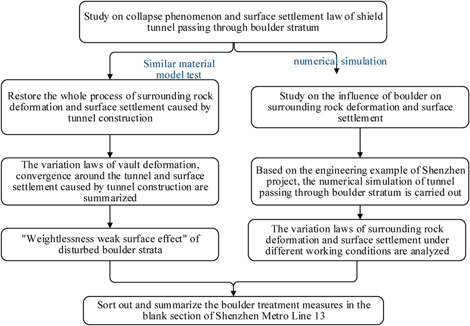
In summary, domestic and foreign scholars have mainly studied the stratum disturbance caused by shield tunnel passing through solitary rock and other bad geology by means of numerical simulation and similar material model test and summarized the relevant treatment measures of shield tunnel passing through the isolated boulder. Generally speaking, relevant scholars mainly focus on the treatment measures of boulders, while there are relatively few research results on the influence of boulders on the deformation of surrounding rock and surface settlement, especially the abnormal disturbance of strata caused by boulders and the occurrence of “weightlessness weak surface effect.” Based on the interval between Liu Xiandong Station and Bai Mang Station of Shenzhen Metro Line 13, with the help of Midas GTS NX finite element numerical simulation software and similar material model test, this paper studies the influence of surrounding rock deformation and surface settlement under the condition of shield passing through solitary rocks, in order to provide some reference for the safe construction of the shield tunnel through the boulder formation in the later stage. The technical road map is shown in Figure 1.
Experimental Study on Similar Material Model of Tunnel Passing Through Solitary Stone Stratum
In the actual engineering of tunnel through rock stratum construction, if the rock is not treated, through direct construction, it is likely to slide and induce the instability of the surrounding rock and soil body, resulting in large formation loss, resulting in the increase of surface subsidence or collapse. Therefore, in the process of tunnel construction, the solitary rock needs to be treated, that is, by the way of ground blasting. If the broken solitary rock is not grouted and reinforced, it is in a loose state. When the tunnel crosses, the loose rock will affect the stability of the surrounding rock and will also produce a too large surrounding rock deformation or even collapse phenomenon. This paper uses the real physical entity (physical model), which, according to the similar principle conditions, truly reflects the spatial relationship between the geological structure and the engineering structure and the accurate simulation construction process, reproduces the tunnel construction deformation, cracking, collapse, and even transmission to the surface, and causes the surface subsidence to the whole process, stress characteristics, deformation trend, and collapse hazard characteristics.
Tunnel collapse usually refers to the phenomenon of a large amount of rock and sediment collapse due to the stress of the rock and sediment on both sides of the tunnel. There are many influencing factors leading to tunnel collapse. The main influencing factors are internal geological factors and human factors. This paper mainly considers geological factors: 1) Structural factors of rock and soil body. Rock and soil mass usually uses the fragmentation degree of the structure or the complete state of the rock and soil mass structure to express the structural state. When the rock and soil mass is in the original state, due to the long-term action of various geological structural movements, the structural surface will produce deformation, dislocation, fracture, and other damage phenomena and lose its original complete state to different degrees. Under the same lithology conditions, the greater the crushing degree of rock mass is, the more likely the tunnel becomes unstable and collapses. This is the right state of the rock broken by ground drilling and blasting, and in this case, it is the most important cause of tunnel collapse and surface collapse. 2) Engineering nature of the rock. The engineering nature of the rock usually refers to the hardness of the rock and the characteristics of the rock structure surface, in which the resistance to the surrounding rock deformation is called the hardness of the rock, which reflects the physical and mechanical properties of the block itself. When the rock mass is relatively complete, the lower the hardness of the rock mass, the worse the stability of the tunnel surrounding rock and the easier it collapses. The appearance of rock mass structure surface is usually caused by the insufficient resistance of rock resistance to shear. The appearance of structural surface not only cuts the complete rock mass but also forms many harmful geological interfaces, such as joints and weak interlayers. Therefore, the shear strength of rock mass structure surface is an important factor affecting the stability of surrounding rock. 3) In addition, the action and influence of groundwater, the initial stress state of surrounding rock, the surrounding rock level, and other geological factors will also affect the stability of surrounding rock during tunnel construction.
In this paper, barite, quartz sand, gypsum, water, and other materials are proportioned according to a certain proportion, and the physical and mechanical properties of the proportioning of the mixed materials are determined through relevant experiments. Through multiple physical and mechanical experiments on the proportioning of the mixed materials, the proportioning of the model materials corresponding to the prototype materials is prepared. Among them, the ratio of barite: quartz sand: gypsum is 13:4:1. The physical and mechanical parameters corresponding to prototype materials and model materials are shown in Table 1.

TABLE 1. Physical and mechanical parameters corresponding to prototype materials and model materials.
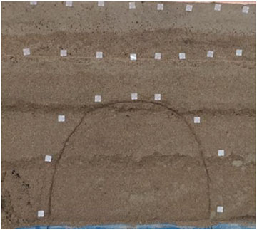
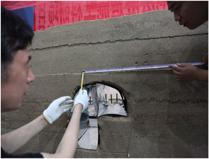
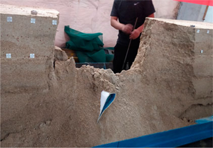
Using quartz sand, mica powder, and barite powder as aggregates and lime and gypsum as cementing materials, a similar material simulation model containing the boulder stratum is constructed for tunnel construction to simulate the whole process of vault deformation, cracking, collapse, and even transmission to the surface on the tunnel cross section, resulting in excessive surface settlement and collapse, as shown in Figures 2–4.
This study uses quartz sand, mica powder, and barite powder as aggregates and lime and gypsum as similar materials, includes a similar material simulation model, tunnel construction, simulated tunnel cross section arch deformation, cracking, collapse, and even transfer to the surface, and causes the whole process of surface subsidence until collapse, as shown in Figure 2∼Figure 6.
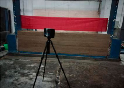
In this paper, the Faro three-dimensional laser scanner is used to monitor the surrounding rock deformation and surface settlement during the tunnel excavation in the simulation test of similar materials, as shown in Figure 5.
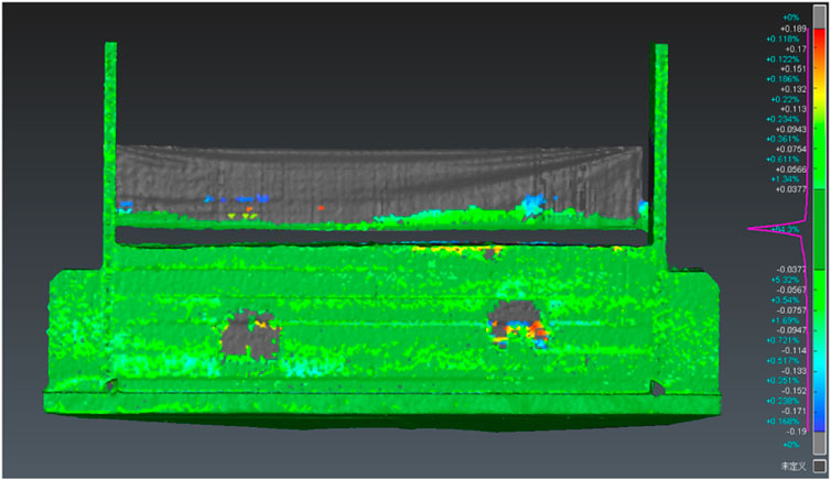
The data processing of the three-dimensional laser scanner is divided into two stages. The first stage includes noise reduction and point cloud splicing. The second stage is to compare and analyze the point clouds before and after two or more times. Before noise reduction and point cloud splicing, the scanned point cloud image format is transformed into a special format FLS, and then the point cloud is imported into scene software for noise reduction and point cloud image splicing. Finally, the noise reduced and spliced point cloud image is only kept within the range we need. On the basis of point cloud image processing in the previous step, the RPS registration function under the conversion tab in 3DReshaper software is used to register the two point clouds to the same coordinate system. The former scanning point cloud is used as the fixed reference point cloud, and the latter scanning point cloud is used as the mobile registration point cloud. The registration of two point cloud maps is carried out in the same coordinate system, the two point cloud files before and after are selected, then the painted object is selected through the comparison/detection function in the measurement tab of 3DReshaper software, and finally 2D or 3D detection is performed to generate the deformation cloud map. The deformation values of the two surface layers can be compared to obtain the displacement of any point on the rock layer and the surface, as shown in Figure 6 and Figure 7.
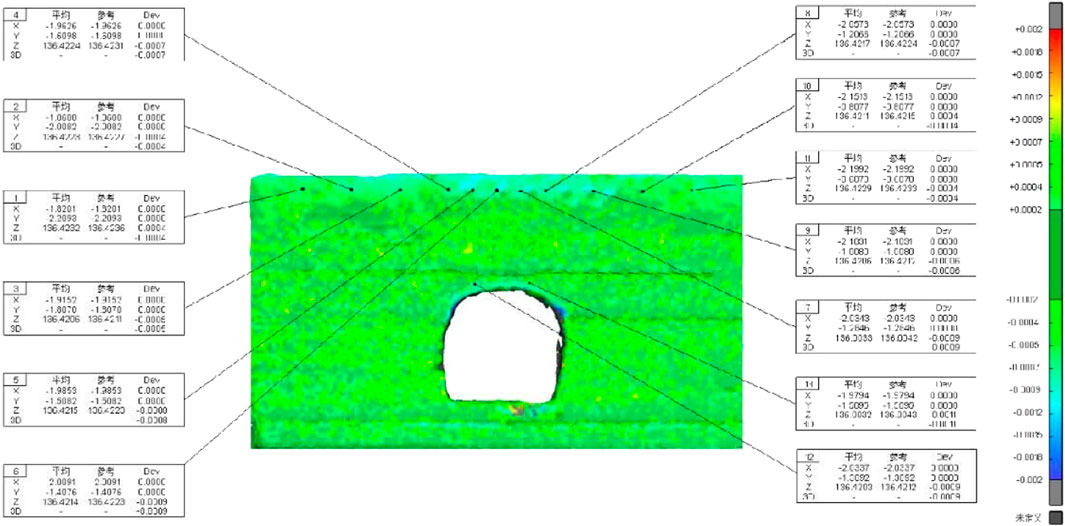
FIGURE 6. Cloud chart of three-dimensional laser scanner monitoring convergence around the tunnel model.
By reproducing and analyzing the deformation characteristics and collapse process of the surrounding rock and even the surface caused by tunnel construction, the following knowledge is mainly obtained: 1) In the model test, the surrounding rock has been disturbed during the tunnel construction process. The surrounding rock above the tunnel vault cracks, which gradually develops and eventually leads to the collapse of the vault. 2) The deformation of the tunnel surrounding rock is monitored by a three-dimensional laser scanner. Some characteristics and rules of tunnel arch subsidence, hole around convergence, and even surface subsidence can be obtained, that is, under normal formation conditions, surface subsidence caused by tunnel construction is a normal and regular phenomenon. When there are special rock components such as solitary rock and joints, there will be a surface subsidence anomaly causing the landslide phenomenon.
Analysis of “Weightlessness Weak Surface Effect” of Boulder Disturbed When Tunnel Passes Through Boulder Stratum
The formation structure of the left-white section of Shenzhen Metro Line 13 is complex, with many types of rock and soil bodies, buried depth, thickness, and own properties. The tunnel crossing the stratum mainly includes strongly weathered granite, moderately weathered granite, and microweathered granite. In the process of tunnel tunneling, there are bad geological conditions such as boulders along the line. If they are not treated, the vault is prone to local damage under no support conditions, and the position relationship between boulders and the longitudinal section of the tunnel is shown in Figure 8.
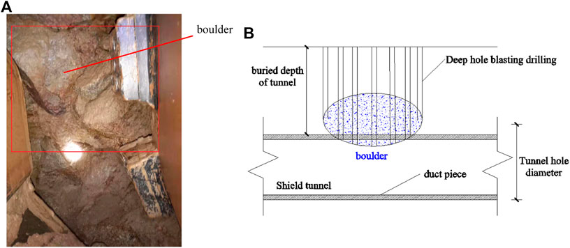
FIGURE 8. Schematic diagram of location distribution of boulders. (A) Location diagram of the boulder distribution in the left ∼ white interval. (B) Schematic diagram of position distribution of boulders in the longitudinal tunnel from left to white interval.
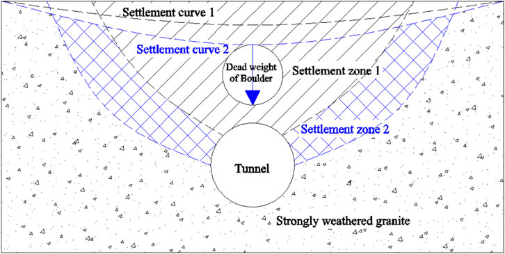
It can be seen from Figure 9 that when the tunnel excavation stratum does not contain boulders, the stratum area caused by the tunnel construction disturbance is mainly settlement area 1, and its stratum settlement curve is settlement curve 1. When the tunnel passes through the boulder stratum, not only the settlement deformation caused by the tunnel construction disturbance will occur near the boulder stratum, but also the stratum crossed by the tunnel is strongly weathered granite, and the stratum below the boulder lacks support, under the self-weight stress of the boulder. It is easy to form the “weightless weak surface” effect, which intensifies the vertical deformation of the stratum between the upper part of the tunnel and the boulder, promotes the continuous increase of the vertical settlement value of the tunnel vault, and finally forms a new settlement curve 2. At the same time, the weightless weak surface effect will drive the corresponding increase of the vertical deformation value of the stratum around and above the boulder, expand the influence range of the tunnel construction disturbance, and form a new settlement basin, as shown in settlement areas 1 and 2 in Figure 9.
Study on the Law of Surrounding Rock Deformation and Surface Settlement During Tunnel Crossing Rock Strata
Establishment of the Numerical Model
Aiming at the stability of the surrounding rock when the tunnel crosses the solitary rock formation, the Midas GTS NX finite element simulation software is used for numerical simulation analysis. The three-dimensional numerical model size is X × Y × Z = 80 m × 45 m × 60 m. In order to facilitate the establishment of 3D model and the determination of boundary conditions, the following three basic assumptions are set: 1) the stratum as a semi-infinite space body; 2) the surrounding rock as a homogeneous and isotropic continuum; and 3) only the self-weight stress field. Based on the above assumption, the lower surface of the model has the fixed end constraint, the X direction constraint is imposed on the left and right surfaces, and the front and back surface is the free boundary; considering the stress of the soil weight, the gravity load factor is 9.807. The 3D model map and grid division diagram of the shield tunnel through the solitary rock stratum are shown in Figure 10. In them, the soil and rock around the tunnel are the Mohr–Coulomb elastic plastic model, which is assumed to be round: the radius is 3 m, and the segment lining is the solid elastic model.
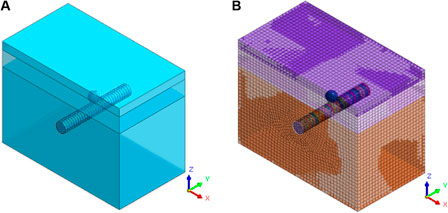
FIGURE 10. Numerical simulation of the tunnel crossing the boulder stratum. (A) Geometric model of the tunnel crossing the solitary formation. (B) Grid model diagram of the tunnel crossing the solitary stone formation.
Selection of Physical and Mechanical Parameters for the Simulation
The formation where the shield tunnel is located is basically strongly weathered granite, and the overlying soil layer is mixed filling soil and hard plastic soil. The physical and mechanical parameters of rock and soil layer, solitary rock, and pipe sheet are shown in Table 2.
Definition of the Conditions Required for the Simulation
Condition 1. Relying on Shenzhen Metro Line 13 leave ∼ between the organizations of the shield tunnel engineering example, the analysis process of the model can be divided into four stages: first stage: calculation of the initial ground stress. Activin soil filling, hard plastic soil, strongly weathered granite, solitary rock, tunnel excavation soil, and zero displacement calculated at this stage simulate the initial stress field of the formation and reduce the calculation error of the model; second stage: ring 1 ∼ 11 ring tunnel excavation soil passivation and corresponding supporting structure activation; third stage: ring 12 ∼ 19 ring tunnel excavation soil passivation and corresponding supporting structure activation; fourth stage: ring 20 ∼ 30 ring tunnel excavation soil passivation and corresponding supporting structure activation simulate shield tunnel excavation.
Condition 2. It is basically the same as Condition 1, but the difference is that, in the first stage, the tunnel and the surrounding soil are activated at the same time and the isolated stone is activated to simulate the surrounding rock and surface deformation caused by the excavation of the shield tunnel under the condition of the existence of the lone stone.
Condition 3. Basically the same as Condition 2, but the difference is in the third stage, when the tunnel is bored near the lone rock and the grouting reinforcement area is activated, so as to simulate the grouting and reinforcement process when the shield tunnel crosses the solitary stone formation.
Analysis of the Simulation Results Under Different Conditions When the Shield Tunneling Passes Through the Boulder Formation
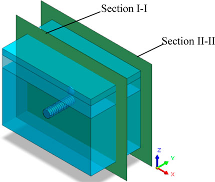
In order to study the influence of boulders on different positions of the tunnel, sections I-I and II-II are specially set. The distance between the above sections is 22.5 and 0 m, respectively, and the specific distribution position is shown in Figure 11.
Analysis of the Surrounding Rock Deformation Characteristics When the Shield Tunnel Crosses the Boulder Formation
In order to study the influence of solitary stones on different sections of the tunnel, the surrounding rock deformation cloud map at section I-I and section II-II was selected for analysis, as shown in Figure 12 and Figure 13 (the surrounding rock deformation of case 1 at section I-I and section II-II is the same, which is only presented in Figure 12). As can be seen from Figure 12, first of all, the area of the vertical deformation concentration area at the vault is from large to small for Condition 1, Condition 2, and Condition 3; at the same time, the vertical deformation concentration area at the arch bottom is Condition 2, Condition 1, and Condition 3 in order from large to small, which can show that grouting and reinforcement of the lone stone formation can have a certain inhibitory effect on the disturbance caused by tunnel construction; secondly, the color of the vertical deformation concentration area of the surrounding rock in Condition 3 is slightly lighter than that in Conditions 1 and 2. This shows that grouting the tunnel can effectively inhibit the deformation of the surrounding rock in the grouting reinforcement area.
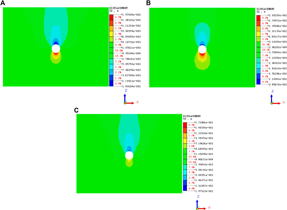
FIGURE 12. Cloud map of section I-I under different conditions. (A) Cloud map of surrounding rock under Condition 1. (B) Cloud map of surrounding rock under Condition 2. (C) Cloud map of surrounding rock under Condition 3.
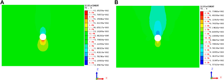
FIGURE 13. Section II-II deformation cloud of surrounding rock under different conditions. (A) Cloud map of surrounding rock under Condition 1. (B) Cloud map of surrounding rock under Condition 2.
As can be seen from Figure 12 and Figure 13, first of all, the cross section II-II cloud surrounding rock deformation under different conditions has certain differences, embodied in condition of two condition of vertical deformation, high arch area is less than one, three conditions, and the arch ascend a bulge deformation, high peak in area in the condition of 2, condition and condition of three deformation, high area, which can explain the boulder strata grouting reinforcement operation can make arch bottom deformation is relatively close to the deformation of surrounding rock in the absence of any boulder; Section in second, the condition of 2 I-I place to be significantly higher than the surrounding rock deformation of the cross section II-II surrounding rock deformation degree, suggesting that close to intensify the deformation degree, from the boulder and condition of three section I-I and cross section II-II place exactly, by contrast, surrounding rock deformation of the grouting reinforcement operation can effectively inhibit the boulder’s influence on the deformation of surrounding rock; Finally, the distribution characteristics of section-Condition 1 and conditions are similar, it may indicate that after the grouting reinforcement operation, the deformation characteristics of the tunnel section far away from the boulder are gradually consistent with the strata without the boulder.
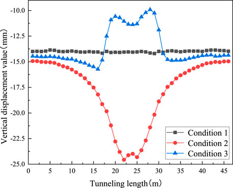
In order to further study the vertical deformation law of the surrounding rock under different conditions, the vertical deformation value of the vault under different conditions is specially selected, and the vertical deformation curve is drawn, as shown in Figure 14. As can be seen from Figure 14, when the tunnel tunneling length is within the range of 0–15 m and 30–45 m, the vertical displacement curve under different operating conditions is approximately a straight line, according to the vertical displacement value from large to small, Condition 2, Condition 3, Condition 1, when the excavation length is within the range of 15–30 m, the vertical displacement curve of Condition 1 is approximately a straight line, Condition 2 is approximate “V” Distribution, the three vertical displacement curve of condition is almost “Double peak of left low right high” Distribution, and within the length of the tunnel, vertical displacement value from large to small in order for Condition 3, Condition 1, Condition 2; Secondly, Condition 2 and Condition 3 reach the maximum and minimum values of the vertical displacement of the surrounding rock at the central point of the rock, it can be shown that the boulder and grouting reinforcement have a significant impact on the surrounding rock deformation; Lastly, the vertical displacement curves of Condition 1 and Condition 2 are approximately symmetrical around cross-sections i-i, while the right displacement of section i-i in the three conditions is slightly less than the left displacement value, it can be explained that the grouting reinforcement can inhibit the surrounding rock deformation caused by the subsequent tunnel construction.
Study on Surface Subsidence Law When Shield Tunnel Crossing Solitary Strata
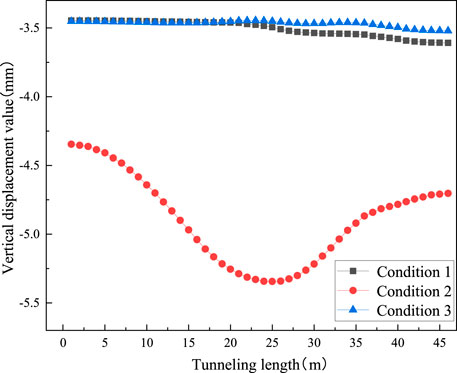
According to Figure 15, the influence of boulder and grouting reinforcement measures on surrounding rock deformation is mainly concentrated near section i-i. The deformation difference between sections-conditions is relatively small. Therefore, the surface settlement curve at section i-i, supplemented by the surface settlement variation under different conditions, and the surface settlement curve at different sections of the tunnel is shown in Figure 15. as can be seen in Figure 15A, the surface settlement curve under different conditions is similar to the normal distribution, it can be shown that the solitary stone and grouting reinforcement measures will not change the distribution characteristics of the surface settlement curve; Secondly, coincident with the surface settlement curve within 0∼40 m from the tunnel center line, however, the surface settlement value of the condition three within the range of-40∼0 m is slightly greater than the condition one, it can be shown that the grouting reinforcement can effectively inhibit the formation deformation caused by boulders; Lastly, the surface settlement value of Condition 2 should be significantly greater than that of Condition 1 and Condition 3, it can show that it is necessary to grouting the solitary rock formation. from Figure 15B, the surface settlement curve of Condition 1 and Condition 3 coincide, and the surface settlement value of Condition 2 is significantly higher than Condition 1 and Condition 3, so that the grouting reinforcement measures can reduce the impact of boulder on formation deformation. Secondly, combined with Figure 13A, the displacement difference between Condition 2 and Condition 1 and Condition 3 is significantly greater than that in Figure 15B, the impact on formation deformation.
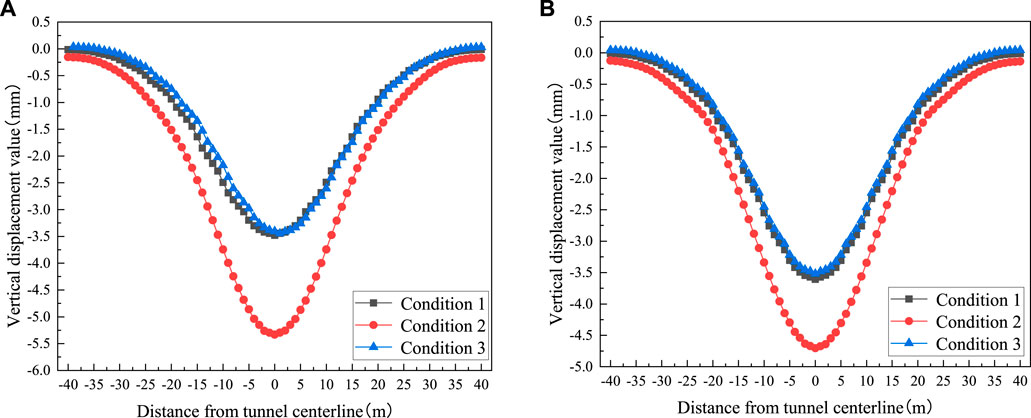
FIGURE 15. Surface settlement curve diagram at different sections of the tunnel. (A) Surface subsidence curve diagram at section I-I.(B) Surface subsidence curve diagram at section II-II.
In order to study the influence of boulders on the longitudinal surface subsidence of the tunnel through the shield tunnel, the longitudinal settlement value of the surface under different conditions was selected, as shown in Figure 16. As can be seen from Figure 16, 1) With the increasing length of tunnel tunneling, The longitudinal settlement value of the surface in Condition 1 and Condition 3 gradually increases, The analysis shows that with the increasing amount of tunnel tunneling length, The influence of the tunnel construction disturbance on the unexcavated formation is gradually increased, The longer the tunneling length is, The longitudinal subsidence value of the ground surface increases accordingly; 2) The longitudinal settlement curve of Condition 1 and Condition 3 is close, It can be seen that the grouting and reinforcement operation of the boulder stratum can effectively inhibit the surrounding rock deformation and surface settlement value caused by the boulders; 3) The maximum longitudinal settlement value of the surface at condition conditions is distributed at 22.5∼27.5 m tunnel length, The location of the stone, And the closer to the stone, The greater the increase in the longitudinal settlement of the ground surface is, According to the analysis, As tunnel construction gradually approaches boulders, Not only will the tunnel vault undergo settlement and deformation under its own gravity, The presence of boulders also strengthens the settlement deformation of the vault, As a result, the maximum longitudinal settlement value of the boulder stratum is mainly distributed in the boulder position; 4) The longitudinal settlement value of the surface under Condition 2 shall be significantly greater than that of Condition 1 and Condition 3, The longitudinal settlement curve of the surface in Condition 2 presents the curve distribution characteristics of “left high and right low”, Condition 1 and Condition 3 are approximate to oblique straight lines, It can be seen that the surface displacement value and distribution characteristics are easily affected by boulders.
Comparison and Analysis of Simulated and Monitored Ground Settlement Values of Tunnel Crossing Boulder Stratum
According to Figure 17, firstly, the variation trend of the surface settlement curve of the numerical simulation value is basically consistent with the curve of the field monitoring value, but the numerical simulation value is generally smaller than the field monitoring value, and the maximum error is not more than 10%. The analysis shows that the constitutive model of rock and soil mass based on the finite element theory and the selected parameter values are different from the field actual situation, In the process of finite element numerical simulation, the construction steps and support methods of the tunnel are simplified to a certain extent. Under the joint influence of the above factors, the simulation value is smaller than the monitoring value; Secondly, the maximum values of the monitored and simulated surface settlement values appear in the center of the tunnel, and the settlement curves are approximately normal distribution; Finally, the monitoring value of ground settlement at the place about 35 m away from the center of the tunnel is about 0 mm, so the influence range on the ground surface during the tunnel construction of the project is about 70 m. To sum up, the variation laws of surface settlement and surrounding rock crown obtained by numerical simulation are basically consistent with the variation laws of field monitoring values, which can explain the feasibility and rationality of numerical simulation to a certain extent.
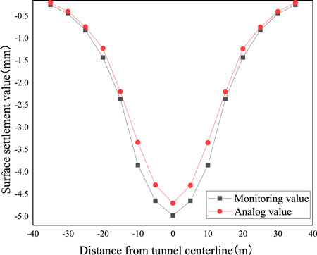
FIGURE 17. Comparison and analysis of simulation value and monitoring value of the tunnel crossing the boulder stratum.
Granite Treatment Measures When the Shield Tunnel Passes Through the Boulder Formation
When the lone rock is encountered in the shield construction and the ground construction conditions, the deep hole blasting treatment will be carried out. The specific operation steps are blasting hole layout, blasting hole taking, charging, gun hole blockage, gun hole coverage, blasting hole, blasting network, explosive single consumption, blasting effect monitoring and grouting, which is described in detail below.
1) Blasting hole layout
According to the location of the solitary rock determined by the geological exploration, the blasting hole layout is carried out, the hole spacing is arranged according to 0.6 m × 0.6 m.Geological drilling hole diameter of 108 mm.Before opening, trenches should be dug to investigate the nearby pipeline situation. When drilling, drill through the road water stabilization layer and use Luoyang shovel to hit 3 m to determine that there is no pipeline below, and then continue to drill. The schematic diagram of the gun hole layout is shown in Figure 8.
2) Blasting hole extraction
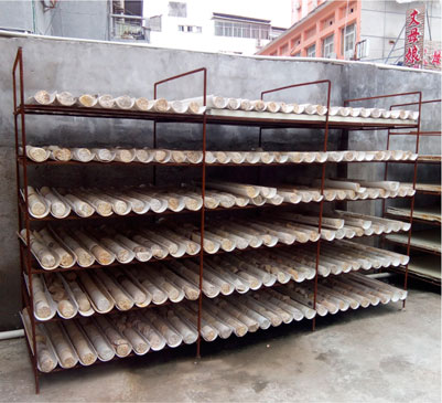
When drilling to the design depth, remove all the gravel, sediment, mud in the hole, use PVC management and protection hole, PVC pipe connection and bottom are sealed with tape. Fill the tube with water to prevent the PVC tube from floating. Keep construction records and retain the rock samples obtained from the drilling hole, as shown in Figure 18.
3) Loading
Put the emulsified explosive into the PVC tube, and place 2∼4 detonators, the charge length is greater than the thickness of the required blasting rock layer. After the medicine package is processed, the explosive medicine package is suspended at the blasting point with nylon wire rope, and one end is fixed at the hole mouth. The obvious markers such as small red cloth strip are tied to the rope to mark, and the length of the mark to the bottom of the PVC pipe is equal to the depth of the whole gun hole (overlay thickness + rock gun hole depth). The medicine package gradually down to the bottom of the gun hole, until the mark on the rope to the gun hole, if in ±10 cm, the approved bag is in place.
4) The blasthole is blocked
After the medicine package is in place, slowly pour sand into the blasthole, and the length of the blockage is greater than 3 m.
5) Artillery hole cover
Since the high pressure gas produced after blasting may press the muddy water in the gun hole out of the hole, in order to prevent the gushing mud water splashing and PVC pipe protrusion, it is necessary to protect the gun hole overhead and heavy pressure cover. Use the concrete precast block, put the concrete precast block on the steel bar frame, use the forklift truck to carry the whole piece, the precast block is placed on the blasting hole.
6) Blasting the network
The gun hole adopts forward loading to burst, the detonator chooses two instantaneous detonators, and respectively belong to two electric burst networks, two sets of networks in parallel.
7) Single consumption of explosives
The single consumption of boulder explosive is 1.8∼5.0 kg/m3. In order to reduce the great impact on the ground construction (structure), the blasting hole distance should be reduced, the blasting number should be increased, and each group of blasting should not exceed 10 holes.
8) Blasting effect detection
After the test blasting, the geological drilling rig is organized to drill again in the blasting area to test the blasting effect. The drilling depth is 1 m below the bottom elevation of the shield section, and the detection frequency is 30% of the number of blasting drilling holes. When drilling the core, if a rock layer of a length greater than 30 cm is found, the area near the core point should be treated again.
9) Injection pulp
Due to the solitary rock treatment blasting construction, the original road surface damage, the underground soil is loose, in order to avoid the pressure loss, the ground drilling grouting should be adopted for the blasting area, the grouting hole spacing is consistent with the blasting hole spacing, the drilling depth is 1.0 m deeper than the original blasting hole depth. After the grouting, the original ground shall be restored. For the asphalt pavement, the blasting grouting area shall be cleaned within 1∼3 m according to the site situation, and the pavement structure shall be applied again.
Conclusion
The deformation and surface settlement of the surrounding rock when the shield tunnel is studied by similar model test and numerical simulation, and the relevant measures of isolated rock treatment in the construction site are summarized to draw the following conclusion:
1) Through similar material model test of tunnel construction caused by the surrounding rock and the deformation characteristics of the surface and collapse process, concluded that shield tunneling, tunnel construction cause surface subsidence is a normal regularity phenomenon, when the formation rock, joints and other special rock component structure, will make the surface subsidence anomaly, and even cause collapse phenomenon.
2) The presence of surrounding rock has obvious effect on the settlement deformation of surrounding rock, and its influence range is not limited to the surrounding location; the surrounding rock deformation is significantly reduced after the grouting reinforcement, which shows that the suppression of the disturbance caused by the tunnel construction.
3) Rock and grouting reinforcement measures did not change the distribution characteristics of surface settlement curve, and grouting reinforcement can effectively inhibit formation deformation caused by rock, and the surface settlement curve overlap, and rock stratum surface settlement value is significantly higher than the above two cases, and the closer the distance, condition, three and conditions of the surface settlement deformation difference is more obvious.
4) By comparing and analyzing the surface settlement curve of the simulation value and the monitoring value when the tunnel passes through the boulder stratum, it is found that the change trend between them is relatively consistent, and the maximum error is less than 10%, which verifies the rationality and accuracy of the numerical simulation to a certain extent.
5) Summarize the construction site stone treatment measures, and the specific contents are as follow: when the shield construction and have the ground construction conditions will be deep hole blasting treatment, operation steps for blasting hole layout, blasting hole, charging, gun hole plugging, blasting network, explosive single consumption, blasting effect monitoring and grouting reinforcement.
Data Availability Statement
The original contributions presented in the study are included in the article/Supplementary Material, further inquiries can be directed to the corresponding author.
Author Contributions
All authors listed have made a substantial, direct, and intellectual contribution to the work and approved it for publication.
Funding
The author(s) disclosed receipt of the following financial support for the research, authorship, and/or publication of thsis article: The research of YG was funded by the National Natural Science Foundation of China (No. 52171264), NSFCRFBR (No. 5191101589), Funded by China State Construction Engineering Corporation Technology R&D Program (CSCEC-2019-Z-19). The research of M.D.K., I.V.M., and A.P.K. was funded by RFBR and NSFC according to the research project No. 20-51-53021.
Conflict of Interest
XP was employed by the company CCCC tunnel engineering company limited, LJ, LH, and CZ were employed by the company China Construction Fifth Bureau 5 South China Company, SP and TZ were employed by the company China Construction Tunnel Construction Co., Ltd.
The remaining authors declare that the research was conducted in the absence of any commercial or financial relationships that could be construed as a potential conflict of interest.
Publisher’s Note
All claims expressed in this article are solely those of the authors and do not necessarily represent those of their affiliated organizations, or those of the publisher, the editors and the reviewers. Any product that may be evaluated in this article, or claim that may be made by its manufacturer, is not guaranteed or endorsed by the publisher.
References
Chen, W., Tan, Y., and Xiang, L. (2018). Study on the Catastrophe Mechanism of Stratum Collapse Induced by Shield Tunneling Damage [J]. Tunn. Constr. Chin. Engl. 38 (05), 824–832.
Hu, Yi (2019). Study on Tunnel Deformation Characteristics of Fully Weathered Strata Containing Solitary Rock [D]. Hunan University of Science and Technology.
Li, X., Zhang, W., and Chen, H. (2021). Analysis of Deformation Law of Super Large Diameter Slurry Shield Tunneling in Boulder Stratum of Sea Cofferdam -- Taking the Shield Section of Shantou Bay Tunnel as an Example [J]. Tunn. Constr. Chin. Engl. 41 (01), 28–36.
Li, Y., Jing, H., and Liu, G. (2007). Application of Digital PhotoMeasurement in Rock Tunnel Model [J]. J. Rock Mech. Eng. (08), 1684–1690.
Liu, H., Huang, J., and Sun, Z. (2016). Application of Micromotion Detection Method in the "solitary Stone" Detection of Urban Metro Shield Construction- -taking Fuzhou Metro Line 1 as an Example [J]. Tunn. Constr. 36 (12), 1500–1506.
Moghaddasi, M. R., and Noorian-Bidgoli, M. (2018). ICA-ANN, ANN and Multiple Regression Models for Prediction of Surface Settlement Caused by Tunneling. Tunn. Undergr. Space Technol. 79, 197–209. doi:10.1016/j.tust.2018.04.016
Selby, A. R. (1999). Tunnelling in Soils–Ground Movements, and Damage to Buildings in Workington, UK[J]. Geotechnical Geol. Eng. 17 (3), 351–371. doi:10.1023/a:1008985814841
Sugiyama, T., Hagiwara, T., Nomoto, T., Nomoto, M., Ano, Y., Mair, R. J., et al. (1999). Observations of Ground Movements during Tunnel Construction by Slurry Shield Method at the Docklands Light Railway Lewisham Extension-East London. Soils Found. 39 (3), 99–112. doi:10.3208/sandf.39.3_99
Wang, P. (2012). Treatment Process and Examples of Shield Engineering under Different Geological Conditions [J]. Tunn. Constr. 32 (04), 571–575.
Zhang, N., Wang, S., and Wang, X. (2007). Experimental Study on Tunnel Deformation and Destruction Process Containing Weak Surrounding Rock [J]. J. Undergr. Space Eng. (06), 1085–1088.
Zhang, W. (2009). Study on the Mechanical Behavior of Initial Tunnel Support Construction under Complex Geological Conditions [D]. Fuzhou University.
Zheng, G., Fan, Q., Zhang, T., Zheng, W., Sun, J., Zhou, H., et al. (2019). Multistage Regulation Strategy as a Tool to Control the Vertical Displacement of Railway Tracks Placed over the Building Site of Two Overlapped Shield Tunnels. Tunn. Undergr. Space Technol. 83, 282–290. doi:10.1016/j.tust.2018.09.040
Zhu, W., Huang, W., and Meng, Q. (2011). Research on the Blasting Technology of Boulder and Bedrock Intrusion in Shield Engineering [J]. Mod. Tunn. Technol. 48 (05), 12–17. doi:10.13807/j.cnki.mtt.2011.05.001
Zhu, X., Qian, W., and Zhu, H. (2021). Numerical Analysis of Stability of Shield Tunneling in Coastal Boulder Stratum [J]. J. Railw. Sci. Eng. 18 (01), 172–183.
Keywords: boulder, shield construction, surrounding rock deformation, surface, tunnel
Citation: Guangming Y, Pengju X, Yongyi Z, Qimeng S, Jun L, Pengfei S, Zhiwen T, Hao L and Ze C (2022) Land Lapse Phenomenon and Surface Subsidence Law of Shield Tunnel Passing Through Rock-Bearing Formation. Front. Earth Sci. 10:934360. doi: 10.3389/feart.2022.934360
Received: 02 May 2022; Accepted: 14 June 2022;
Published: 29 August 2022.
Edited by:
Bo Li, Tongji University, ChinaReviewed by:
Zhanping Song, Xi’an University of Architecture and Technology, ChinaMinghao Liu, Chinese Academy of Sciences (CAS), China
Copyright © 2022 Guangming, Pengju, Yongyi, Qimeng, Jun, Pengfei, Zhiwen, Hao and Ze. This is an open-access article distributed under the terms of the Creative Commons Attribution License (CC BY). The use, distribution or reproduction in other forums is permitted, provided the original author(s) and the copyright owner(s) are credited and that the original publication in this journal is cited, in accordance with accepted academic practice. No use, distribution or reproduction is permitted which does not comply with these terms.
*Correspondence: Zhang Yongyi, MTc5NDcwMDcxNUBxcS5jb20=
 Yu Guangming1
 Zhang Yongyi