 Denghong Chen
 Yongqiang Yuan
 Li Ma1,2*
- 1School of Mining Engineering, Anhui University of Science and Technology, Huainan, China
- 2Wanbei Coal-Electricity Group Co., Ltd, Suzhou, China
Taking the engineering conditions of the Zhujixi coal mine and Hengyuan coal mine in the Wanbei mining area as the background, based on the investigation of the deformation and failure status of the surrounding rock of the two mines, the deformation and failure characteristics of the surrounding rock of the deep rock roadway in the Wanbei mining area are systematically studied by using the comprehensive research methods of the surrounding rock mechanical parameter test, in situ stress measurements, and numerical simulation. The results show that the measured value of the intermediate principal stress is slightly less than the theoretical value, which is obviously affected by the tectonic stress. The lateral pressure coefficients of the two mines calculated according to the theory are between 1.06 and 1.24 and 1.18 and 1.24, respectively. The simulation shows that when the lateral pressure is higher than 1.5, the arrangement of drilling holes with a depth of 5–10 m and a diameter of 200–300 mm can effectively transfer the stress concentration, proposed using Ф22 L = 2800 mm anchor rods, row spacing 800 × 800 mm, specification Ф 22. For the anchor cable with a length of L = 6,300 mm, the row spacing between anchor cables is 1,600 ± 100 mm, and the coordinated support technology of the reinforcement support and grouting is added. The technology can fully mobilize the deep stable rock stratum when it is applied from the slope change point of 11 coal belt roadways in the east wing of the Zhujixi coal mine to the machine head chamber of 11 coal belt roadways in the west wing, and the field application is good.
Introduction
With the development of the world economy, the mineral resources in the shallow part of the earth are gradually exhausted, and the resource development continues to move toward the deep part of the earth. At the same time, the human demand for survival and development and the exploration of the unknown world also continue to expand the underground activity space. In terms of resource mining, the mining depth of nonferrous metal mines is more than 4,350 m, and the geothermal mining depth is more than 3,000 m. As the main fossil energy resource endowed by nature, the mining depth of coal has reached 1,500 m. In the future, the mining of deep resources will become the norm (Xie et al., 2015; Xie et al., 2021a). The stress level of the surrounding rock of the shallow roadway is low, the stress concentration caused by excavation is low, and the deformation and fracture range of the surrounding rock is small. It can be effectively controlled by the conventional support. In contrast, the surrounding rock of the deep roadway is in the special stress environment of “three high and one disturbance,” and is often subject to complex geological tectonic movement, forming obvious regional and directional high-horizontal stress. The surrounding rock of the roadway shows significant non-linear soft rock mechanical characteristics, serious fragmentation and expansion, and poor support and maintenance effects (Hou et al., 2021a; Xie et al., 2021b; Zhang, 2020). The horizontal stress of a deep roadway will be several times larger than that in the shallow roadway, resulting in a more complex mechanical environment. Especially, without considering the influence of the high-horizontal stress direction, mining design and excavation will often cause sudden convergence deformation and collapse damage of the surrounding rock of the development roadway and working face, roof subsidence, and serious floor heave. It will even lead to dynamic failure such as rockburst (Zhu, 2018; Zhao et al., 2021).
Theoretical and engineering practice research has shown that under the current support level, blindly increasing the support strength and support density cannot better control the large deformation of the roadway surrounding rock (Ma et al., 2015). The research shows that the surrounding rock of underground engineering is usually subjected to the coupling action of compressive stress and shear stress (Du et al., 2021); according to the variation trend of acoustic emission blow count and acoustic emission energy characteristic parameters, the rock fracture process shows obvious piecewise variation characteristics and has a significant growth cycle (Du et al., 2020). In deep mines, due to the sudden fracture of the hard roof in the mining process, the roadway may also be subjected to dynamic load (Yin et al., 2020); the increase of axial preloading stress is helpful to improve the crack growth rate and reduce the dynamic crack initiation toughness (Yin et al., 2014). Through the numerical calculation and on-site teaching and research on the rock mass excavation process of the underground powerhouse of the Xiaolangdi water control project, Zhu Weishen and others believe that the support structure has a significant effect on fixing the loose and broken rock mass of the surrounding rock and preventing its collapse and falling off (Zhu et al., 2006). Through the analysis and research on the measured data of roadway surrounding rock deformation in Huainan, Pingdingshan, and other mining areas, Yang Chao and others believe that increasing the support resistance is mainly to curb the expansion of the roadway surrounding rock fracture area (Yang et al., 2000). The subsidence of roadway roofs has little correlation with the support strength provided by the existing support equipment. Increasing the high continuous support resistance can prevent the caving of the loose surrounding rock (Fan et al., 2003). Hou Chaojiong put forward the basic theory and technical framework of surrounding rock control in the deep roadway, which takes the strengthening of the surrounding rock as the core and the active stress intervention and grouting modification as the support (Hou et al., 2021b). According to Wang Weijun’s research, high stress will lead to continuous deformation of the roadway surrounding rock dominated by plastic deformation (Wang et al., 2016). Meng Qingbin found that the supporting stress field of the bolt and anchor cable improves the disturbed stress field of the surrounding rock after roadway excavation, inhibits the generation of the tensile stress zone, reduces the shear stress zone, and limits the tensile and shear failure of coal and rock mass (Meng et al., 2017).
To sum up, the original rock stress value of the deep roadway is much greater than the strength of the surrounding rock, and the original rock stress is the main influencing factor of large deformation, failure, and instability of the surrounding rock of the roadway. At present, there are few in-depth studies on the deformation and failure characteristics and control technology of surrounding rocks in deep high-horizontal stress rock roadways. The interaction principle between such roadway supports and surrounding rocks needs to be clarified. Targeted prevention and control countermeasures such as optimization of layout orientation, pressure relief in high-stress areas of the surrounding rock, and asymmetric support in low-stress areas are difficult to put forward. In this work, the influence of deep high-horizontal stress on the deformation and failure characteristics of the rock roadway surrounding rock is studied by means of field tests and numerical calculations.
Engineering Background
The Hengyuan coal mine and Zhujixi coal mine in the Wanbei mining area have successively entered deep mining. The Zhujixi coal mine is located in the north of the Huainan coalfield and in the west section of the Zhuji—Tangji anticline. The occurrence form of coal seams in the mine is generally an axial NW syncline structure, which is controlled by regional large faults. The mine is located in the footwall of North–South reverse faults, and there are large tensile faults in the north of the northern reverse fault group. The rock layer near the Hengyuan coal mine is a monoclinic structure with an inclination of 3–20°, and the overall geological conditions are relatively simple. The normal fault DF56 may be exposed in the later stage of tunneling. According to different roadway types, the two mines have used a variety of support methods, including the bolt mesh shotcrete support, the bolt mesh cable support, the bolt cable coupling support, bolt meshes, the cable shotcrete grouting support, and other support forms, but have not achieved good support results. In order to study the deformation and failure characteristics of the surrounding rock of the deep high-horizontal stress rock roadway in the Wanbei mining area, rock coring and in situ stress tests were carried out in the above two mines in order to carry out the subsequent geomechanical evaluation of the deep roadway.
Geomechanical Assessment of Deep Roadways
Testing of Mechanical Parameters Around Surrounding Rocks
In order to provide corresponding parameters for the subsequent in situ stress test and numerical simulation, the author took two holes in the roof and floor, respectively, at two positions with an interval of about 20 m in the 11 coal track roadway on the West Wing of the Zhujixi mine and the 940 m return air auxiliary crosscut of the Hengyuan coal mine and processed the core to obtain standard samples according to the relevant national test standards. Using the RMT-150 rock mechanics testing machine, the tensile strength and compressive strength of the sample are tested at the loading speed of 0.1 KN/s, and the basic mechanical parameters of the rock body are obtained. The flow of the surrounding rock mechanical parameter test of the two mines is shown in Figures 1, 2.

FIGURE 1. Compressive failure process of the rock.
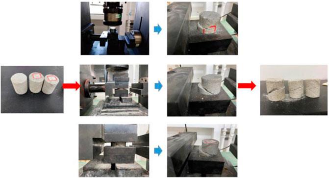
FIGURE 2. Flow chart of the rock shear test.
Through the overall analysis of the mechanical parameters of the cores taken from the two mines, it is obtained that the top and bottom slates of the 11 coal track roadway in the West Wing of the Zhujixi mine are mainly sandstone–mudstone, in which the tensile strength of the mudstone is low, ranging from 0.8 to 1.7 MPa, the compressive strength is about 20.1 MPa, and the tensile strength of some sandy mudstones is 4.79 MPa. The maximum compressive strength of the sandstone is 109.5 MPa, with high strength; Sandstone cohesion c = 12.58 MPa, and internal friction angle φ = 38.51°. The results show that the lithology of the roof of the Hengyuan mine and the 940 return air auxiliary crosscut is mainly mudstone and the lithology of the floor is mainly sandstone. The tensile strength of mudstone is low, ranging from 1.661 to 4.442 MPa, and the compressive strength is 28.27–49.65 MPa. The highest compressive strength of the sandstone is 73.695 MPa, followed by the strength; Sandstone cohesion c = 5.765 MPa, and internal friction angle φ = 23.17°. Based on the above analysis, it is found that the mechanical properties of the surrounding rock of the Hengyuan return air auxiliary crosscut roadway are better than those of the Zhujixi 11 coal roadway.
Test of in situ Stress
In order to ensure the stability of underground rock mass engineering, various factors affecting the engineering stability must be fully investigated and studied. Among many influencing factors, the in situ stress state of rock mass is one of the important factors. For mine roadway engineering, only by mastering the in situ stress conditions of specific engineering areas can we reasonably determine the roadway direction, optimal section shape, size, excavation steps, support forms, and support parameters.
In order to obtain the in situ stress distribution of the Hengyuan coal mine and Zhujixi coal mine, the in situ measurement of in situ stress was carried out by using the stress relief method. The field measurement process is shown in Figure 3. In this measurement, a hollow inclusion stress meter is used to measure the two sides of the 11 coal track roadway on the West Wing of Zhujixi mine and the 940 m return air auxiliary crosscut of the Hengyuan coal mine at an interval of about 20 m. The measured data are stress-relieved. Some stress relief process curves are shown in Figure 4, and then the magnitude and direction of in situ stress at the measured position are deduced by professional software.
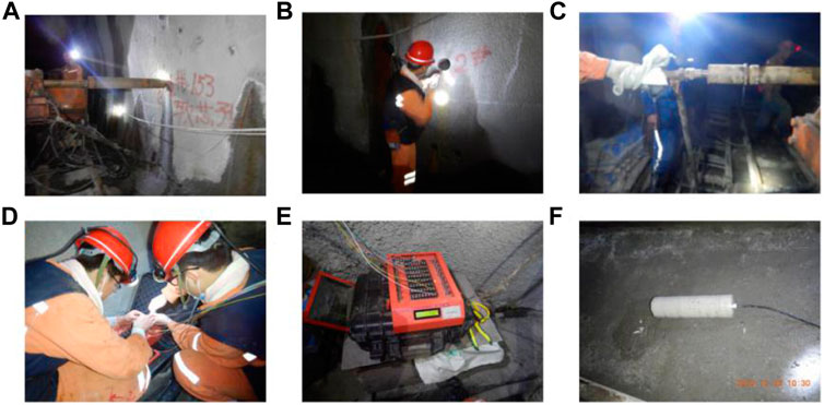
FIGURE 3. Flow chart of the rock shear test. (A) Adjust the orientation of the drilling rig. (B) Start drilling test holes. (C) Install the hollow enclosure. (D) Relieve the stress of hollow inclusion. (E) Collect strain gauge data. (F) Core pulling.
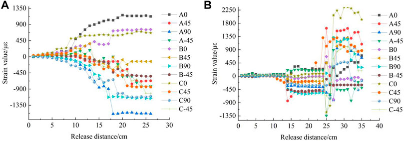
FIGURE 4. Stress relief process curve. (A) Survey points of the 11 coal track roadway in the West Wing of the Zhujixi mine. (B) Shengyuan mine–940 return air auxiliary crosscut measuring point.
As can be seen from Figure 4, the stress relief process of hollow inclusion carried out by two mining coring drill heads can be roughly divided into three stages: there is no disturbance relief influence area, and the strain curve is basically in a state of little change. This process is mainly because the coring bit has not been pushed to the position of the strain gauge. In the stress elastic release area, at this time, the strain value of each strain gauge increases rapidly with the increase of release distance, indicating that the coring bit is rapidly passing near the hollow inclusion stress gauge where the strain gauge is located and stripping it from the complete rock. Due to the removal of the core boundary constraint around the stress gauge, the hollow inclusion stress gauge will rebound and expand properly with the core. In the strain stability zone, the strain value of each strain gauge tends to be flat and fluctuates up and down in a small range, marking the end of the stress relief process.
It can also be seen from Figure 4 that the lifting distance of the two mines in the non-lifting disturbance-affected area is the same, both between 0 and 12 cm, while the lifting range of the stress elastic release area of the Zhujixi mine is 7 cm less than that of the Hengyuan mine, the strain stability area of the Zhujixi mine starts from 18 cm, and the strain stability area of the Hengyuan mine starts from 25 cm. This shows that the difference of the in-situ stress field between the two mines is obvious.
The in situ stress measurement by the hollow inclusion stress meter method is to calculate the stress through the strain value in the stress relief process of the rock mass to be measured around the stress meter and combined with the elastic mechanical parameters reflecting the stress–strain relationship of the rock mass. Therefore, the determination of rock elastic parameters at the measuring point is particularly important. Table 1 shows the rock mechanics parameters selected in the in situ stress calculation of the two mines.
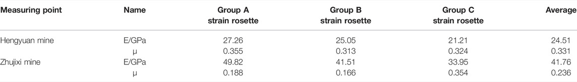
TABLE 1. Rock mechanical parameters selected in in situ stress calculations.
By comprehensively analyzing all the data in the above progress process and using Mathcad calculation software for calculations and processing, the in situ stress distribution state of the 11 coal track roadway in the West Wing of the Zhujixi mine is obtained. It is found that the maximum principal stress at the location of the roadway is between 25.6 and 29.9 MPa, and the azimuth of the maximum principal stress is mainly distributed in NE192° and NE94.5°、NE98.3, and the inclination angle is mainly less than 30°. The intermediate principal stress is between 22.3 and 23.6 MPa. The minimum principal stress is mainly distributed between 16.3 and 18.4 MPa, the azimuth is approximately orthogonal to the azimuth of the maximum principal stress, and the inclination is relatively small, showing a near-horizontal distribution. At 25 Kn/m3, the overburden pressure calculated by the average unit weight is 24.05 MPa, the measured value of the intermediate principal stress is slightly less than the theoretical calculation value, which is obviously affected by the tectonic stress, and the lateral pressure coefficient calculated according to the theory is between 1.06 and 1.24.
The in situ stress distribution state of the Hengyuan mine with the 940 return air auxiliary crosscut is obtained. It is found that the maximum principal stress at the location of the roadway is between 27.91 and 29.18 MPa, the azimuth of the maximum principal stress is mainly distributed in NE109.9°–NE129.21°, the inclination angle is mainly less than 45°, and the intermediate principal stress is between 17.6 and 19.9 MPa. The minimum principal stress is mainly distributed between 11.4 and 13.3 MPa; at 25 Kn/m3, the overburden pressure calculated by the average unit weight is 23.5 MPa, the measured value of the intermediate principal stress is slightly less than the theoretical calculation value, which is obviously affected by the tectonic stress, and the lateral pressure coefficient calculated according to the theory is between 1.18 and 1.24.
Simulation and Optimization of the Surrounding Rock Control Scheme of the Deep High-Horizontal Stress Roadway
Model Establishment
In this analysis, FLAC3D finite difference software is used to simulate the roadway deformation, and the modeling is based on the design size of the 11 coal track roadway in the West Wing of the Zhujixi mine, and the model size is 60 m × 10 m × 40 m. The buried depth of the roadway is 940 m, the vertical stress is 23.5 MPa, and the mechanical model adopts the Mohr–Coulomb criterion. After the model is established, the horizontal displacement constraint is applied to the boundaries on both sides, the vertical displacement constraint is applied to the bottom, the lateral displacement constraint is applied to the front and rear surfaces, and the stress boundary is applied to the top surface. The model is shown in Figure 5.
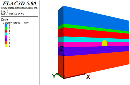
FIGURE 5. Numerical simulation model.
Simulation Scheme Design
According to the theory of mine pressure behavior and deep rock stratum control and combined with the main problems of the roadway support at present, 15 simulation schemes are orthogonally designed according to different lateral pressure coefficients, support parameters, and roof and floor lithology (mudstone, siltstone, and fine sandstone), including high-strength bolt φ22 × 2,800 mm and anchor cable φ φ22 × 6,300 mm as shown in Table 2.
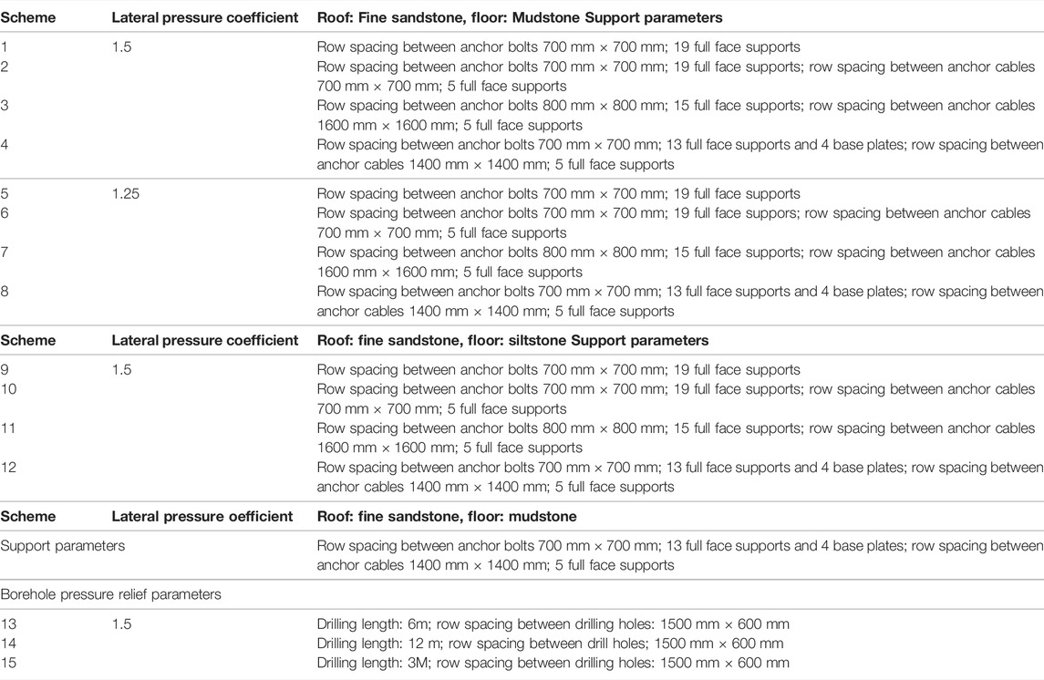
TABLE 2. Numerical simulation scheme of the roadway surrounding rock.
Numerical Simulation Results
In order to understand the distribution of roadway stress, the failure of the plastic zone, and the change of support stress under different simulation schemes, various simulation results are comprehensively analyzed.
Comparing the simulation results of schemes 1–4, as shown in Figure 6, it can be seen from the cloud diagram of ZZ stress distribution that there is no special stress concentration as in scheme 3. The distribution position of the maximum-horizontal stress extends from the roadway side foot to the middle of the left and right sides of the roadway, and the maximum value reaches 10.248 MPa; the vertical stress is mainly tensile at the top and bottom of the roadway, with the maximum value of 1.7837 MPa, while the stress on the roadway side is 23.627 MPa. It can be found that the tensile force on the top of scheme 4 is 0.327 MPa lower than that in scheme 3, and the pressure on the two sides basically does not increase. At the same time, the maximum stress on the anchor cable is 0.30359 MPa, which is also lower than that in scheme 3. However, the plastic zone of the roadway shoulder is expanded to 2.6 m, which is 0.4 m less than that of scheme 3, and the plastic zone of the side is expanded by 2.6 m as in scheme 3. Schemes 1 to 4 are the comparison results of various supports under the vertical stress with the lateral pressure coefficient of 1.5 times. It can be clearly found that the support mode of scheme 4 is more conducive to the stability of the roadway surrounding rock and less damage to the anchor cable.
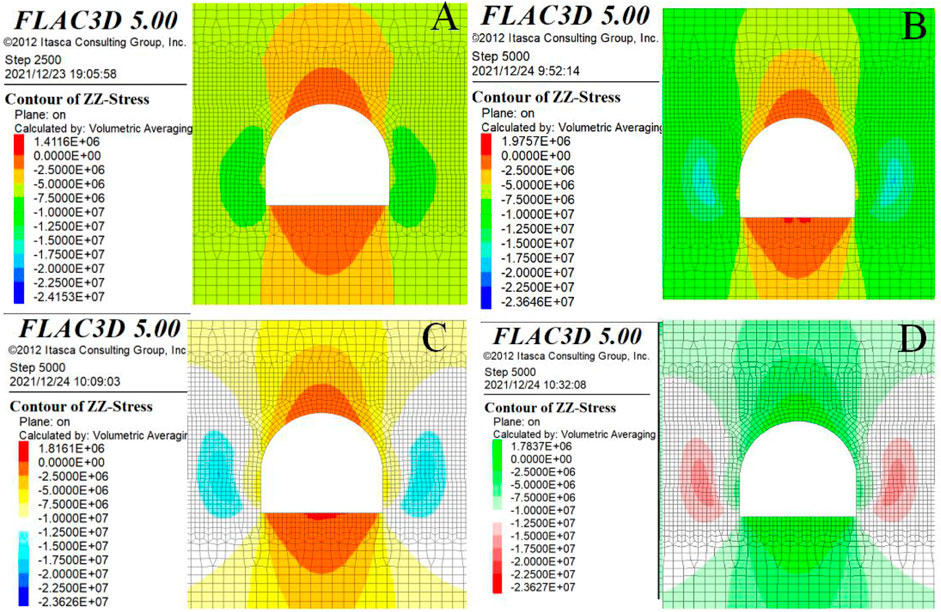
FIGURE 6. Cloud diagram of ZZ stress distribution. (A) Option 1. (B) Option 2. (C) Option 3. (D) Option 4.
Comparing the simulation results of schemes 5 to 8, as shown in Figure 7, it can be seen from the cloud diagram of XX stress distribution that there is no stress expansion like scheme 7, with the maximum tensile value of 4.4498 MPa and the maximum compressive value of 4.4281 MPa; the distribution position of the position with the maximum-horizontal stress is similar to the first three schemes, and the maximum value is 0.51719 MPa; the vertical stress is mainly tensile at the top and bottom of the roadway, with the maximum value of 1.8082 MPa, while the stress at the roadway side is 23.627 MPa. At the same time, the maximum stress of the anchor cable is 0.30372 MPa, which is also increased to a certain extent compared with scheme 3. However, the position of the plastic zone at the roadway shoulder is expanded to 2.8 m, which is increased by 0.2 m compared with scheme 3, and the plastic zone at the side is expanded by 2.6 m as in scheme 3. Schemes 5 to 8 are the comparison results of various supports under the vertical stress with the lateral pressure coefficient of 1.25 times. It can be clearly found that the support mode of scheme 7 is more conducive to the stability of the roadway surrounding rock and less damage to anchor cables. Schemes 9 to 12 are under the vertical stress with the lateral pressure coefficient of 1.5 times, and the comparison results of various supports after the lithology of the surrounding rock are changed; it can be clearly found that the support mode of scheme 12 is more conducive to the stability of the roadway surrounding rock.
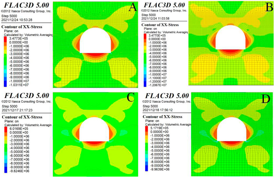
FIGURE 7. Cloud diagram of ZZ stress distribution. (A) Option 5. (B) Option 6. (C) Option 7. (D) Option 8.
A certain number of boreholes are drilled in the surrounding rock of the roadway in the high-stress area. Under the action of stress, the borehole wall is collapsed, a certain crushing area is formed around the borehole, and the failure areas of adjacent boreholes are connected to form a large-scale failure zone. The high-stress roadway realizes pressure relief by arranging boreholes: the boreholes are crushed, releasing energy and transferring the stress peak to the deep, which reduces the stress concentration of the coal seam and improves the stress environment of the roadway. Drilling changes the physical and mechanical bearing characteristics, reduces the brittleness of the coal seam and the ability of the coal seam to store elastic properties, and thus reduces the possibility of local stress concentration in the surrounding rock of the roadway. Figure 8 shows the simulation results of different borehole pressure relief parameters.
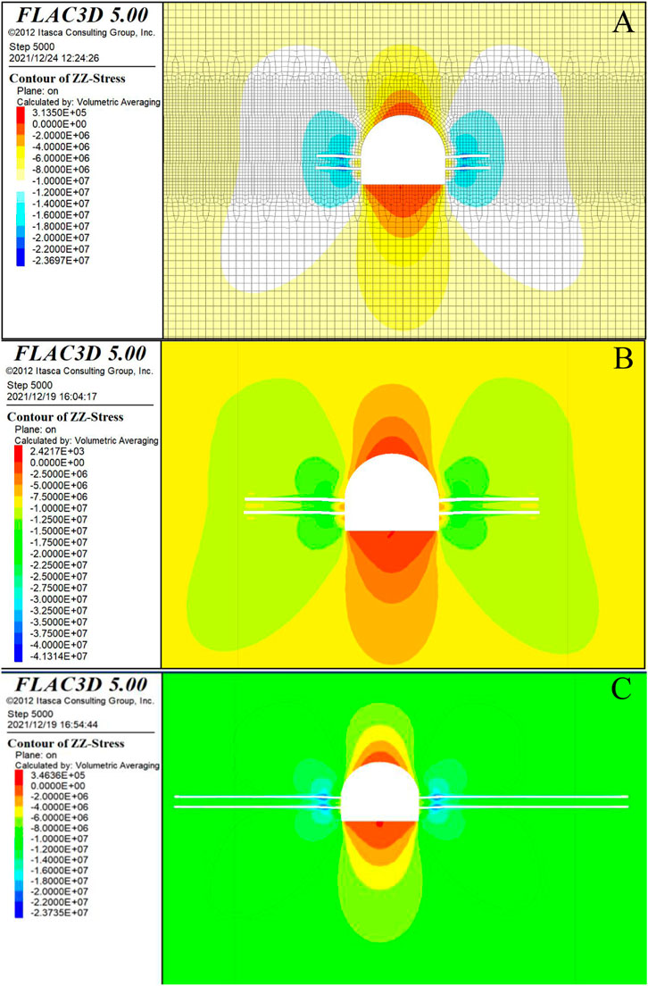
FIGURE 8. Borehole pressure relief ZZ stress distribution nephogram. (A) Option 13. (B) Option 14. (C) Option 15.
From the simulation results, it can be seen that the stress in the vertical direction of the roadway decreases in the vault and floor of the roadway, and the stress around the two sides of the borehole decreases slightly. There is still a slight stress concentration at the corner points such as the arch waist and the foot of the sidewall. The stress concentration zone is transferred around the borehole. The maximum stress value of scheme 13 is 22.5 MPa, that of scheme 14 is 23.735 MPa, and that of scheme 15 is 23.697 MPa. In the actual pressure relief construction, due to the different working faces, different material properties, and the requirements of drilling technology and construction efficiency, it is reasonable to arrange the drilling depth of 5–10 m, which depends on the specific stope conditions.
Through comparison, it is found that the simulated support parameter is the row spacing between bolts of 700 mm × 700 mm, 13 full section supports, 4 base plates, and a 1,400 mm row spacing between anchor cables compared with other schemes; the simulation effect of the scheme of 1,400 mm and 5 full face supports is more obvious; and the damage of the anchor cable is less. When the above support parameters are used to simulate after changing the roof and floor rock properties, the plastic zone of the roadway side is expanded to 1.2 m and the plastic zone of the floor is expanded to 1.8 m. It can be clearly found that this support method is more conducive to the stability of the surrounding rock of the roadway floor. In the actual pressure relief construction, due to the different working faces, different material properties, and the requirements of drilling technology and construction efficiency, when the lateral pressure is higher than 1.5, the drilling depth is 5–10 m and the hole diameter is 200–300 mm, which can effectively transfer the stress concentration, depending on the specific stope conditions. Coordinated control technology of the deep high-horizontal stress roadway is required.
Coordinated Control Technology of the Deep High-Horizontal Stress Roadway
After on-site investigation, it is found that from the slope change point of the No. 11 coal belt roadway in the West Wing of Zhuji to the machine head chamber of the No. 11 coal belt roadway in the West Wing of Zhuji, it is compressed and deformed, squeezing the belt conveyor in the roadway and restricting safety production. The deformation of the on-site investigation roadway is shown in Figure 9.
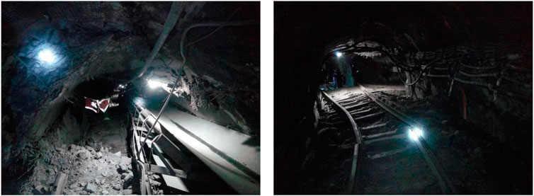
FIGURE 9. Field investigation on the deformation status of the 11 coal belt roadway.
Then, under the results of numerical simulation, the coordinated control is carried out from the slope change point of the 11 coal belt roadway in the east wing to the head chamber of the 11 coal belt roadway in the West Wing of the Zhujixi coal mine. The anchor mesh shotcrete cable support is adopted for permanent support Ф 22, L = 2,800 mm left-hand non-longitudinal reinforcement high-strength deformed steel bolts, with a row spacing of 800 × 800 mm. 1 × 19 strand high-strength anchor cables with specification Ф 22 are used. The length is L = 6,300 mm, the exposed length is 150–250 mm, and the row spacing between anchor cables is 1,600 ± 100 mm. The reinforced support anchor bolt and anchor cable are alternately arranged in the whole cross-section between the transverse and longitudinal middle of the original primary support anchor bolt, and the rows between adjacent anchor bolts and anchor cables are 800 × 800 mm. Grouting is also carried out for the machine head chamber and belt roadway of the 11 coal belt roadway. The diameter of the grouting pipe is 20 mm, and the grouting material is a single liquid cement slurry. The supporting section is shown in Figure 10.
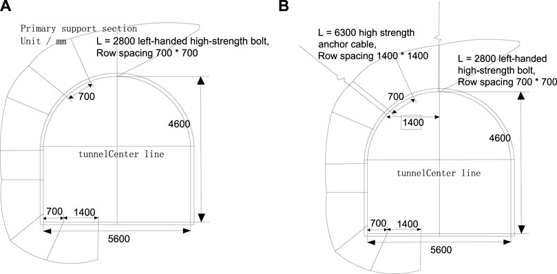
FIGURE 10. Support section. (A) Permanent support. (B) Reinforcement support.
After adopting the coordinated control technology of the deep high-horizontal stress roadway, the field investigation on the support of the East Wing 11 coal belt roadway is carried out, and it can be seen that the support effect is remarkable, as shown in Figure 11.
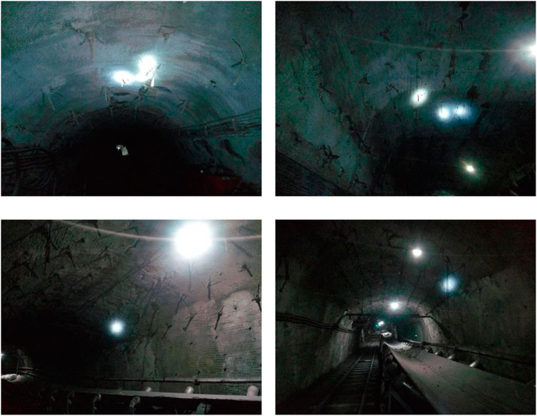
FIGURE 11. Support effect of the 11 coal belt roadway in the west-east wing of Zhuji.
In order to further verify the roadway support effect, a borehole peeping camera is used to peep at the roadway after support, as shown in Figure 12. From the results, it can be seen that there is no obvious separation in the deep part of the roadway.
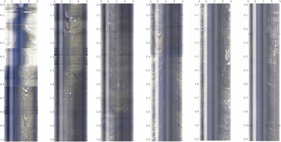
FIGURE 12. Peeping through 0–6 m boreholes in the 11 coal belt roadway in the west-east wing of Zhuji.
Conclusion
(1) Through the test, the mechanical parameters of the deep rock roadway surrounding rock in the Zhujixi coal mine and Hengyuan coal mine are obtained. Among them, the top and bottom slates of the 11 coal track roadway in the West Wing of the Zhujixi mine are mainly sandstone–mudstone. The tensile strength of mudstone is low, ranging from 0.8 to 1.7 mpa, and the compressive strength is about 20.1 mpa. The maximum compressive strength of sandstone is 109.5 mpa, the cohesion of sandstone C = 12.58 mpa, and the internal friction angle φ = 38.51°. The roof lithology of the Hengyuan mine and the 940 return air auxiliary crosscut is mainly mudstone, and the floor lithology is mainly sandstone. The tensile strength of mudstone is low, ranging from 1.6 to 4.4 mpa, and the compressive strength is 28.27–49.65 mp. The compressive strength of sandstone is up to 73.6 mpa, the cohesion of sandstone C = 5.7 mpa, and the internal friction angle φ = 23.17°.
(2) Through the test, the in situ stress occurrence characteristics of the typical deep rock roadway in the Zhujixi coal mine and Hengyuan coal mine are obtained. The maximum principal stress at the location of the 11 coal track roadway on the West Wing of the Zhujixi mine is 25.6–29.9 mpa, the middle principal stress is 22.3–23.6 mpa, and the minimum principal stress is mainly distributed between 16.3 and 18.4 mpa. The maximum principal stress at the location of the Hengyuan mine and the 940 return air auxiliary crosscut is 27.9–29.1 mpa, the middle principal stress is 17.6–19.9 mpa, and the minimum principal stress is mainly distributed between 11.4 and 13.3 mpa. The measured value of the intermediate principal stress is slightly less than the theoretical calculation value, which is obviously affected by the tectonic stress. The lateral pressure coefficients of the two mines calculated according to the theory are between 1.06 and 1.24 and between 1.18 and 1.24, respectively.
(3) The optimization scheme of the coordinated control technology is obtained by numerical simulation. Through comparison, it is found that the simulated support parameter is the row spacing between bolts of 700 mm × 700 mm, 13 full section supports, 4 base plates, and a 1400 mm row spacing between anchor cables × 1400 mm, and it can be clearly found that this support method is more conducive to the stability of the roadway floor surrounding rock. In the actual pressure relief construction, due to the different working faces, different material properties, and the requirements of drilling technology and construction efficiency, when the lateral pressure is higher than 1.5, the drilling depth is 5–10 m and the hole diameter is 200–300 mm, which can effectively transfer the stress concentration, depending on the specific stope conditions.
(4) The coordinated control technology is implemented from the slope change point of the 11 coal belt roadway in the east wing of the Zhujixi coal mine to the machine head chamber of the 11 coal belt roadway in the west wing. In the 11 coal belt roadway in the east wing of the Zhujixi coal mine, which is one of the places where the technology is implemented, it is found that the technology can fully mobilize the deep stable rock stratum by using the borehole peeping technology and on-site actual monitoring.
Data Availability Statement
The original contributions presented in the study are included in the article/supplementary material; further inquiries can be directed to the corresponding author.
Author Contributions
All authors contributed to this work. DC prepared and edited the manuscript. DC and YY substantially contributed to the data analysis and revised the article. DC, YY, and LM reviewed the manuscript and processed the investigation during the research process.
Funding
The project was supported by the National Natural Science Foundation of China (51974008); the University Synergy Program of Anhui Province(GXXT-2020-008),the graduate innovation fund project of Anhui University of Technology (2021CX2012); and the National Key R&D Plan (2019YFC1904300).
Conflict of Interest
LM and YY were employed by Wanbei Coal-Electricity Group Co., Ltd.
The remaining author declares that the research was conducted in the absence of any commercial or financial relationships that could be construed as a potential conflict of interest.
Publisher’s Note
All claims expressed in this article are solely those of the authors and do not necessarily represent those of their affiliated organizations or those of the publisher, the editors, and the reviewers. Any product that may be evaluated in this article or claim that may be made by its manufacturer is not guaranteed or endorsed by the publisher.
References
Du, K., Li, X., Tao, M., and Wang, S., (2020).Experimental Study on Acoustic Emission (AE) Characteristics and Crack Classification during Rock Fracture in Several Basic Lab Tests. Int. J. Rock Mech. Mining Sci., 133:104411. doi:10.1016/j.ijrmms.2020.104411
Du, K., Li, X., Wang, S., Tao, M., Li, G., and Wang, S.,(2021) .Compression-shear Failure Properties and Acoustic Emission (AE) Characteristics of Rocks in Variable Angle Shear and Direct Shear Tests. Measurement, 183:109814. doi:10.1016/j.measurement.2021.109814
Fan, K. G., Zhai, D. Y., Jiang, J. Q., and Jiang, J. Q. (2003). The Shape of Plastic Area and Fracture Ring of Thin Layer Weakness Structure in Roadsides, 4, 6–8. 1003-5923,04-0006-03.
Hou, C. J., Wang, X. Y., and Bai, J. (2021a). Basic Theory and Technology Study of Stability Control for Surrounding Rock in Deep Roadway. J. china Univ. mining Technol. 50 (01), 1–12.
Hou, C, J., Wang, X, Y., Bai, J, B., Meng, N, K., and Wu, W, D. (2021b). Research on Basic Theory and Technology of Surrounding Rock Stability Control of Deep Roadway. J. China Univ. mining Technol. 50, 1–12. doi:10.13247/j.cnki.jcumt.001242
Ma, N. J., Zhao, X. D., Zhao, Z. Q., Li, J., and Guo, X. F. (2015). Stability Analysis and Control Technology of Mine Roadway Roof in Deep Mining. J. China Coal Soc. 40, 2287–2295. doi:10.13225/j.Cnki.jccs.6011
Meng, Q. B., Han, L. J., Zhang, F. G., Zhang, J., Nin, J. W., and Wen, S. Y. (2017). Coupling Support Effect on High-Stress Deep Soft Rock Roadway and its Application. Rock Soil Mech. 38 (05), 1424–1435+1444. doi:10.16285/j.rsm.2017.05.025
Wang, W. J., Yuan, C., Yu, W. J., Wu, H., Peng, W. Q., Peng, G., et al. (2016). Stability Control Method of Surrounding Rock in Deep Roadway with Large Deformation. Jour-nal China Coal Soc. 41 (12), 2921–2931. doi:10.13225/j.cnki.jccs.1115
Xie, H, P., Gao, F., and Ju, Y. (2015). Research and Development of Rock Mechanics in Deep. J. rock Mech. Eng. 34, 2161–2178. doi:10.13722/j.cnki.jrme.1369
Xie, H, P., Li, C, B., Gao, M, Z., Zhang, R., Gao, F., and Zhu, J, B. (2021a). Conception and Preliminary Exploration of Deep In-Situ Rock Mechanics in Coal Journal. J. rock Mech. Eng. 40, 217–232. doi:10.13722/j.cnki.jrme.0317
Xie, H, P., Ren, S, H., Xie, Y, C., and Jiao, X, M. (2021b). Development Opportunities of Coal Industry under the Goal of Carbon Neutralization. J. coal. 46, 2197–2211. doi:10.13225/j.cnki.jccs.0973
Yang, C., Lu, S. L., and Jiang, Y. D. (2000). Controlling Effects of Support Resistance on Roadway Deformation under Different Rock Conditions. J. China Univ. Mining Tech. 29, 170–173. DIO:1000-1964,02-0170-04.
Yin, Z. Q., Ma, H. F., Ma, H. F., Hu, Z. X., and Zou, Y. Effect of Static - Dynamic Coupling Loading on Fracture Toughness and Failure Characteristics in Marble. J. Eng. Sci. Technol. Rev., 2014, 7(2): 169–174. doi:10.25103/jestr.072.25
Yin, Z., Chen, W., Hao, H., Chang, J., Zhao, G., Chen, Z., et al. ,(2020). Dynamic Compressive Test of Gas-Containing Coal Using a Modified Split Hopkinson Pressure Bar System, Rock Mech. Rock Eng., 53(2): 815–829. doi:10.1007/s00603-019-01955-w
Zhang, Y, H. (2020). Study on Deep In-Situ Stress Measurement Method Considering Non-linear Elasticity of Rock Mass. Beijing: Beijing University of science and technology. doi:10.26945/d.cnki.gbjku.000098
Zhao, X., Wang, J., Qin, X. H., and Chen, Q. C.,(2021).In-situ Stress Measurements at Depth and Engineering Application at China's Underground Research Laboratory Site for High-Level Radioactive Waste Disposal. J. Cent. South Univ. (Science Technology).52,2634–2645. doi:10.11817/j.issn.1672-7207.08.011
Zhu, L.,(2018).Study on Deformation Mechanism of Surrounding Rock in Different Directions under High Horizontal Stress. doi:10.27275/d.cnki.gsdku.001239
Keywords: deep high-horizontal stress, side pressure coefficient, stability of roadway surrounding rocks, coordinated control technology, pressure relief and reinforcement
Citation: Chen D, Yuan Y and Ma L (2022) Deformation and Failure Characteristics and Control Technology of Surrounding Rocks in Deep High-Horizontal Stress Rock Roadways in the Wanbei Mining Area. Front. Earth Sci. 10:886221. doi: 10.3389/feart.2022.886221
Received: 28 February 2022; Accepted: 17 March 2022;
Published: 27 April 2022.
Edited by:
Yilin Gui, Queensland University of Technology, AustraliaReviewed by:
Bowen Wu, China University of Mining and Technology, ChinaXiangyu Wang, China University of Mining and Technology, China
Copyright © 2022 Chen, Yuan and Ma. This is an open-access article distributed under the terms of the Creative Commons Attribution License (CC BY). The use, distribution or reproduction in other forums is permitted, provided the original author(s) and the copyright owner(s) are credited and that the original publication in this journal is cited, in accordance with accepted academic practice. No use, distribution or reproduction is permitted which does not comply with these terms.
*Correspondence: Denghong Chen, ZGhjaGVuQGF1c3QuZWR1LmNu; Li Ma, MzQ4MzA2NTg1QHFxLmNvbQ==