- 1State Key Laboratory of Geomechanics and Geotechnical Engineering, Institute of Rock and Soil Mechanics, Chinese Academy of Sciences, Wuhan, China
- 2University of Chinese Academy of Sciences, Beijing, China
Long-term water seepage in shield tunnels has a serious impact on water and soil loading on the outer surfaces of a shield segment near water areas. A theoretical analysis was used to obtain a formula to express the average vertical seepage gradient at the top of the tunnel. A formula for calculating the coefficient of lateral earth pressure for the principal stress arch effect was utilized. A model that takes into consideration the effects of long-term water seepage on the shield tunnel’s water and soil load was designed. Based on this calculation model, the variation law of the water and soil loading on top of shield tunnel near water area with the internal friction angle in the soil body, the density of the soil, the tunnel depth-to-diameter ratio, the water head of the external section, and the amount of water seepage per unit length is studied. Based on the geological conditions and field survey results of water and soil loading of two typical segments of the Maliuzhou Waterway section of the Hengqin Tunnel, a comparative analysis of the theoretical results and field survey measurements was performed for different calculated conditions. The research shows that the proposed model is able to perform a reasonably effective evaluation of the water and soil pressure at the top of the shield tunnel for the marine and land segments of the shield tunnel; and, when compared with Dimitrios Kolymbas’ effective stress method and Terzaghi’s Principle, the method shown in this paper has fewer errors. The results of the associated research are sufficient to reasonably design and propose a theoretical basis for underwater shield tunnels.
1 Introduction
With the implementation of strategies aimed at strengthening China’s transportation infrastructure and as underwater shield tunnels gradually trend toward increased diameters and shallower overlying soils, the phenomenon of water seepage has begun occurring (Wang et al., 2019). The water and soil load on the top of shield tunnels contains two elements: soil pressure produced by the deformation of rock and soil and the water pressure from the effects of groundwater (Metro tunnel design specification, 2003). Tunnel water seepage will lead to changes in the surrounding seepage and stress fields, thus impacting the magnitude of water and soil loading on the outer surface of the shield segment. A reasonably effective evaluation of the water and soil load on the outer surface of shallow shield tunnel segments has consistently been a hot topic and focal point both domestically and abroad as use of inaccurate values can lead to a series of problems, including tunnel deformation and instability, damage to the segment structure and increased project costs arising from material waste (Zhang et al., 2002).
Therefore, extensive research has been conducted on the subject by researchers at home and abroad. On the aspect of water pressure calculation, Kyung-Ho. (2008), Fernandez. (2008), and Mohamed. (2010) took analytical approaches to the seepage field of a drained and circular tunnel. Du and Wang. (2011) proposed a method for the analysis of underwater tunnel fields for tunnels influenced by linings and grouting rings. Zhu et al. (2017), proposed an analytic solution for tunnel seepage fields in tunnels influenced by depth and linings. Li et al. (2020), analysed the effect of grouting rings on tunnel seepage fields under different conditions of outer lining drainage. Cui et al. (2019, 2017, 2015a, b) presented numerical solution of the surrounding rock mass pressure by considering the rock mass as strain softening and confining-stress-dependent. Liu et al. (2019), performed analyses of the seepage fields in surrounding rocks, grouting rings and liners of the Linhai Tunnel. Additionally, He et al. (2020) and Zhang et al. (2018), obtained analytical solutions for tunnel seepage fields by considering the impact of non-Darcy seepage flow while Zhang et al. (2020) and Fu et al. (2021), analysed tunnel seepage fields under the effect of far-field and near-fault water heads. On the aspect of soil pressure calculation, Terzaghi presented a sliding failure mode for overlying soil layers of shallow shield tunnels buried in sandy soils based on experimental results of the sliding door model and proposed a formula for calculating the vertical loose earth pressure on the top of a tunnel:
where Pv is the vertical loose earth pressure on the top of the tunnel, γ is the density of the soil body, c is soil cohesion, φ is the angle of internal friction within the soil body, K is the lateral soil pressure coefficient for the sliding surface overlying the top of the tunnel with a suggested value of 1, H is tunnel depth and B is the width of the sliding section overlying the top of the tunnel, where B =
However, a large number of practical experiments have shown that there exists a definite discrepancy between the results of loose earth pressure calculations for sandy soils and the actual measured values in the field (Li et al., 2015), and researchers both at home and abroad have since performed revisions on the Terzaghi earth pressure theory and explored other ways of calculating soil pressure. Koyama. (2003) revised the value of the coefficient of lateral earth pressure. Li. (2014) proposed the concept of a small principal stress arch effect, thus formulating a new solution for vertical soil pressure at the top of a tunnel. Wang et al. (2019), conducted an analysis of the mechanisms of gradual arching in strata. Wan et al. (2019), separated the overlying soil body into three parts - the rectangular arching, the potential collapse, and the parabolic arching zones - and formulated a model for calculating the loose earth pressure of overlying soils. Li et al. (2020), conducted an inverse analysis of loads on the outer sections of underwater shield tunnel linings based on the results of field surveys. Zhang et al. (2019), performed a comparative analysis of the different calculation methods for vertical earth pressure on shield tunnels and their practicality based on the results of field surveys. Xiao et al. (2019), analysed the surrounding rock pressure of shield tunnels within composite strata. Zhang et al. (2016), investigated the soil arching effect and coefficient of lateral earth pressure at the top of tunnels and formulated a new type of predictive model for the height of developed soil arching. Chen and Peng. (2018), formulated a new type of soil pressure evaluation model, taking into consideration the non-linear distribution characteristic of the height of developed soil arching and the soil pressure at the top of a tunnel based on the buoyancy of tunnels in Shanghai’s soft soil region. Yu et al. (2019), performed a three-dimensional theoretical model analysis on the buoyant shear-slip model for deep tunnels.
In summary, there have already been numerous studies on the theory for calculating overlying water and soil loading on shield tunnels. Furthermore, there are relatively mature water pressure calculations and many theoretical calculation models. Moreover, the Terzaghi soil pressure principle is also in widespread use. All this information provides a theoretical basis for the design of underwater shield tunnels. However, it is not difficult to see that the current design theories and research conclusions are simply a superposition of soil and water pressures (Dimitrios, 2007; Zhao et al., 2017a; Zhao et al., 2017b; Maleki, 2018; Liu et al., 2019; Bi et al., 2020; Wang et al., 2020; Wei and Zhu, 2021; Bi et al., 2022; Liu et al., 2022). Therefore, when it comes to calculating water and soil loading for shallow shield tunnels near water areas, further discussion is still needed to account for the impact of changes in water level, actual flow field, value of the coefficient of lateral earth pressure and other problems. In light of this fact, this paper first presents an analysis of the seepage field for the marine and terrestrial segments of a tunnel, thus establishing a model with which to calculate water and soil loading on top of the tunnel. Then, with the Maliuzhou Waterway section of the Hengqin Tunnel as the object of research, in order to validate the efficacy of the calculation method proposed in this paper, a comparative analysis is performed using the results of the calculation methods proposed in this paper, actual field measurements and results of other theoretical calculations. This is done with the hope that the associated research will be able to provide a beneficial theoretical basis and support for underwater shield tunnel design.
2 Seepage field analysis for shallow underwater shield tunnels
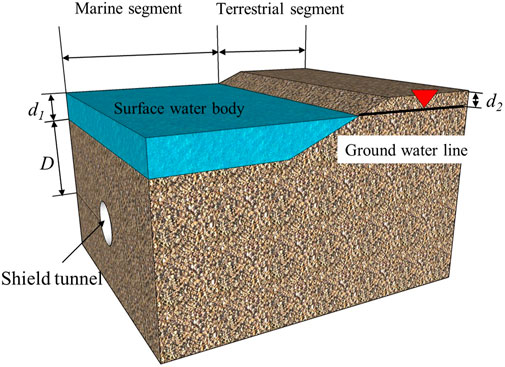
An underwater shield tunnel can be divided into terrestrial and marine segments in the direction of a tunnel’s central axis, as shown in Figure 1, where R is tunnel radius, D is the distance between the central axis of the tunnel and the surface, d1 and d2 are distances between the water level and the surface of the marine and terrestrial segments, respectively and B is the width of the sliding section at the top of the tunnel. The water level is located above the surface in the marine segment and below the surface in the terrestrial section. Therefore, two sets of conditions exist for the underwater shield tunnel: underwater excavation and excavation in a semi-infinite aquifer. Under normal circumstances, surface water and groundwater levels of the Linjiang terrestrial segment are fixed and solutions are found using a fixed water head boundary condition without taking into consideration the complementary water flow conditions along the direction of the central axis of the tunnel. An analysis of the marine and terrestrial segments can be simplified into two dimensions using the calculation method shown in Figure 2 (where P0 is the support force at the top of the tunnel). Assuming that the rock surrounding the tunnel is a continuous, homogeneous medium of isotropic porosity, the seepage coefficient of the surrounding rock is k. Under conditions of long-term water seepage, the seepage field of the rock surrounding the outer section of the shield tunnel can be considered to have already reached a stable seepage state, and an analysis can be performed according to conditions of stable seepage.
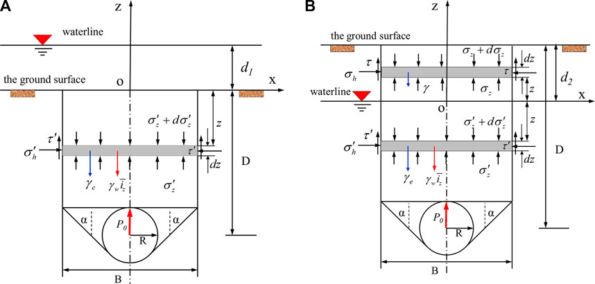
FIGURE 2. Analysis model of water and soil load on the top of a marine shield tunnel. (A) marine segment, (B) terrestrial segment.
According to Darcy’s Law, the equation that governs stable groundwater seepage is:
where ϕ(x,z) is the total water head at any point within the surrounding rock. Performing calculations with Eq. 2 based on the boundary conditions of the terrestrial and marine segments, an analysis of the tunnel seepage field can be obtained.
2.1 Marine segment
With the plane of the ground surface as the datum of reference and ignoring the impact of atmospheric pressure, the seepage boundary condition at the ground surface is
With a fixed water head at the outer section of the shield tunnel, its water seepage boundary condition is
where
The water pressure at any point in the rock surrounding the tunnel is represented by
where p(x,z) is the pore water pressure at any point in the surrounding rock below the water level,
2.2 Terrestrial segment
Because ground water receives long-term replenishment from water at the surface, it is assumed that the groundwater level of the terrestrial segment is essentially equivalent to the water level at the surface and that the groundwater level does not change with tunnel seepage. With the plane of the groundwater level as the datum of reference and ignoring the impact of atmospheric pressure, the seepage boundary condition at the groundwater level is
The water head at the outer section of the shield tunnel is still assumed to be a fixed water head, and its seepage boundary condition is shown in Eq. 4. Under the special condition when the seepage field of the marine segment of the shield tunnel d1 = 0, the seepage field of the terrestrial segment of the shield tunnel is solved using
where d2 is the thickness of the strata above the groundwater level in the terrestrial segment.
3 Analysis of water and soil loading on top of a tunnel: The effect of long-term seepage
3.1 Soil pressure on top of the marine segment of the tunnel
According to the Terzaghi sliding failure mode for the overlying soil body of a shield tunnel, a rock body of thickness dz at a distance z below the ground surface is selected to serve as an object of research for this analysis as shown in Figure 2A. The following assumptions are made for the convenience of using these equations for theoretical analysis: (1) the sliding surfaces within the model are all in their ultimate state of strength, (2) the impact of the vertical seepage force within the sliding section on top of the tunnel is taken into consideration and (3) the vertical seepage gradient is evenly distributed within the rock surrounding the sliding section on top of the tunnel with an average seepage gradient of
where
where
Substituting Eq. 10 into Eq. 9 based on the ground surface effective stress boundary condition
Using Eq. 5 to directly solve for the seepage gradient
where
Combining Eqs 11, 12 can solve for the soil pressure at the top of the marine segment of the shield tunnel (z = R - D):
3.2 Soil pressure on top of the terrestrial segment of the tunnel
For the terrestrial segment, the groundwater level is beneath the ground surface, and for the terrestrial segment of the Linjiang Ocean Shield Tunnel, the groundwater level is generally located above the top of the tunnel. Not taking into consideration the effect of matrix suction and finding separate solutions for the sections above and below the groundwater level, the analytical model shown in Figure 2B is obtained. The differential forces acting on the sliding section of the soil body above the groundwater level are self-gravity,
where γ is the natural density of the soil body above the water level.
The shear stress at the face of the sliding section below the groundwater level can be calculated according to Eq. 10 while the shear stress at the face of the sliding section above the groundwater level is
where Kc is the coefficient of vertical earth pressure for the shear at the face of the slip surface above the groundwater level and c and φ are cohesion and angle of internal friction of the rock and soil body above the water level, respectively. Considering that the groundwater level in land next to the shore is generally higher and that there exists a capillary water effect, the values c and φ used in the calculations for the rocky soil body above the water level are selected according to their saturated state.
If the boundary conditions are
According to Eq. 8, the average seepage force gradient iz within the sliding section of the terrestrial segment of the tunnel is
where
Combining Eqs 17, 18 can solve for the earth pressure on top of the tunnel for the terrestrial segment of the shield tunnel (z = R + d2 - D) as
For a medium load structure model, the water and soil loads
where pw is the water pressure at the top of the tunnel, which can be solved for according to Eqs 5–7.
3.3 Investigating the coefficient of lateral earth pressure for the surface of the sliding section
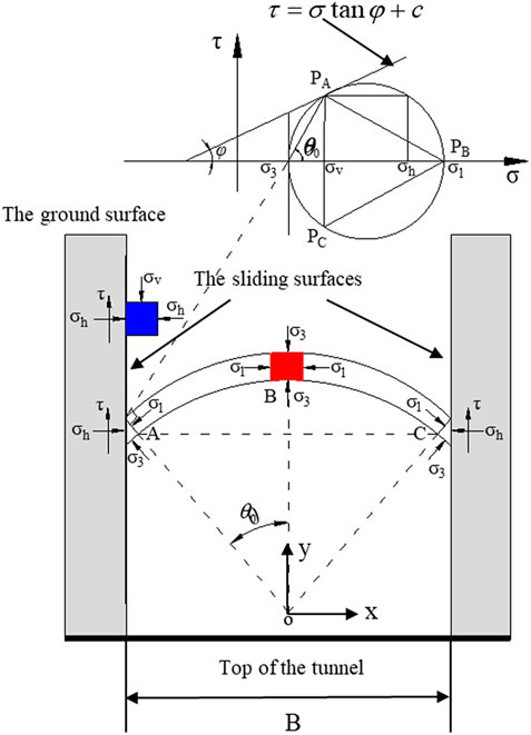
The coefficient of lateral earth pressure is one of the key parameters of the Terzaghi loose earth pressure theory. However, a consensus has still not been reached in the calculation of the coefficient of lateral earth pressure K, with the primary point of controversy being the selection of the principal arch stress to be used in the calculation (Handy, 1985; Wan et al., 2019; Wang et al., 2019; Fan et al., 2022). Xu et al. (2018) and Dong et al. (2022) discovered that a convex principal stress arch is more aligned with actual circumstances and the principal stress arch traces adopt a circular arc form. In addition, the majority of past research and results are based on conditions of sandy strata, and, therefore, the applicability of the coefficient of lateral earth pressure formula to cohesive substrata has not been settled. On the basis of prior research, this paper adopts assumed conditions for the principal stress arch and establishes an analytical model for the convex circular arc form shown in Figure 3. In Figure 3, PA and PB are two poles of the Mohr stress circle.
The rocky soil body of the sliding surface is in a limit equilibrium state. Based on the limit equilibrium conditions and the geometric relationship in Figure 3, the horizontal stress
where
K, the ratio of the horizontal earth pressure to the vertical earth pressure at any point, is expressed as
Because the rocky soil body within the sliding section is in an active fault state, the coefficient of active earth pressure in the equation is
The average vertical stress is
where
The distribution coefficient m for the vertical earth pressure is
According to Figure 3, the shear stress τ at point A of the shear-slip surface satisfies
where KA is the ratio of the horizontal earth pressure and
The coefficient of lateral earth pressure for the shear-slip surface is
According to the geometrical relationship between the Mohr stress circle and the extreme failure envelope of the
Equation 29 can be simplified to obtain
Because of φ, the angle of internal friction within the soil body is typically less than 90⁰ and
from which can be obtained
It is clear from Eq. 32 that the formula for the angle of rotation of the principal stress obtained in this paper is consistent with the formula for the angle of rotation of the principal stress in sandy strata obtained by Handy (1985). Further, it can be seen that the angle of rotation of the principal stress in the soil body is only associated with the angle of internal friction within the soil body and that the coefficient of lateral earth pressure is a function of the angle of rotation of principal stress. This shows that this paper’s model for calculating the coefficient of lateral earth pressure can be applied to both sandy and cohesive strata. By substituting Eq. 32 into Eq. 28 and simplifying, the coefficient of lateral earth pressure of the shear-slip surface can be obtained:
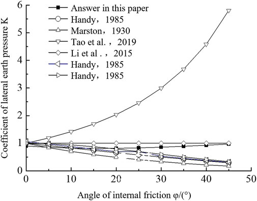
A comparative analysis has been performed using this paper’s model for calculating the coefficient of lateral earth pressure and other existing formulas as shown in Figure 4. Through an analysis of the figure, when the results from this paper’s model are placed alongside those from existing theoretical calculations, the validity of this paper’s model for calculating the coefficient of lateral earth pressure is clear. Furthermore, it can also be seen from the figure that the coefficient of lateral earth pressure changes with increases in the angle of internal friction within the rocky soil body by first slightly decreasing and then increasing. This could be primarily due to the impact of the soil arching effect during the soil deformation process, showing that there are certain conditions where the soil arching effect is a driving influence on the coefficient of lateral earth pressure. Before the soil arching effect begins, the coefficient of lateral earth pressure decreases slightly with an increase in the angle of internal friction. After the soil arching effect forms, soil arching is a driving influence on the changes in the coefficient of lateral earth pressure, and as the angle of internal friction increases, the coefficient of lateral earth pressure increases and the soil arching effect is more evident, which aligns with established facts.
4 Parameter impact analysis
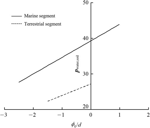
4.1 The impact of the tunnel’s depth - diameter ratio
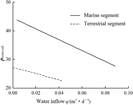
When the distance between the water level and the ground surface is d1 = d2 = 10 m, the cohesive strength of the rocky soil body is c = 20 kPa, the angle of internal friction
4.2 The impact of the density of the rocky soil body
When the distance between the water level and the ground surface is d1 = d2 = 10 m, the cohesive strength of the rocky soil body is c = 20 kPa, the angle of internal friction φ = 30⁰, the tunnel is fully drained, the radius of the tunnel is R = 5 m, and the tunnel depth is D = 30 m. The water and soil loading on the top of the shield tunnel changes with different values of the saturated density γ of the rocky soil body, as shown in Figure 6. Through an analysis of the figure, it is clear that as the volumetric weight of the soil body increases, the water and soil load on the top of the tunnel experiences a gradual linear increase.
4.3 The impact of drainage conditions
When the distance between the water level and the ground surface is d1 = d2 = 10 m, the cohesive strength of the rocky soil body is c = 20 kPa, the angle of internal friction
5 Project applications and verifications
5.1 Project overview
The Maliuzhou segment of the Hengqin Tunnel is the object of our research. This tunnel is located in the section between Working Well No. Three and Financial Island. The Maliuzhou Waterway is in the YDK8 + 100∼ + 700 segment with a waterway width of 600 m and water depth of 5–8 m. The geological profile of the Maliuzhou Waterway shield construction segment of the Hengqin tunnel is shown in Figure 9. The strata surrounding the tunnel are primarily silt, fine clay, medium-grade, coarse and fine sands and weathered granite. According to the engineering geological conditions and engineering characteristics of Hengqin Tunnel, static penetration test, standard penetration test and dynamic penetration test, pressure meter test and indoor soil test were carried out for the main soil layers. Through the statistical analysis of these test results, the paper obtains the values of cohesion and angle of internal friction of geotechnical masses. The primary physical and mechanical parameters are shown in Table 1. The shield construction section of the tunnel uses a total of four composite-style earth pressure equilibrium shields with linings of prefabricated reinforced concrete. The shield tunnel’s inner diameter is 7.7 m, its outer diameter is 8.5 m, its segment width is 1.6 m and its segment liner thickness is 400 mm.
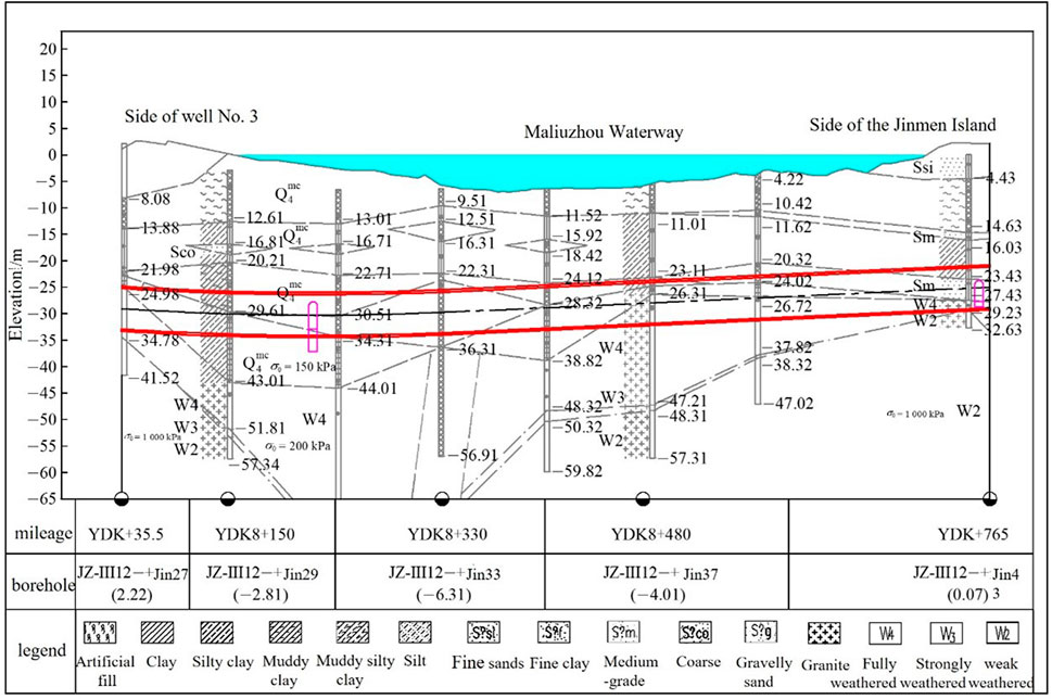
FIGURE 9. Geological section of the construction section of the Hengqin Tunnel passing through the Maciuzhou Waterway.
According to the preliminary geological exploration results of Hengqin Tunnel, two sections of the shield tunnel were selected to measure the changes in water and soil pressure on the outside of the shield tunnel in the direction of Well No. Three on the northern shore beneath the waterway and in the direction of Financial Island to the south. A basic overview of the measured sections is as follows:
Section I: YDK8 + 339.5 at a buried depth of 18.7 m and water depth of 5–8 m in the bottom section of the Maliuzhou Waterway. Overlying strata is composed of fluid plastic silt, fine plastic clay and a thin layer of silty clay. The tunnel passes through a stratum of moderate-density coarse sand.
Section II: YDK8 + 765.1 at a buried depth of 22.5 m and water depth of 5–8 m in the northern shore of the Maliuzhou Waterway. Overlying strata is composed of loose fine sand, fluid plastic silt, a thin layer of slightly dense fine sand, fine plastic clay and clay. The tunnel passes through an arched stratum of plastic clay, a middle stratum of moderately dense sand and a bottom stratum of weatherized granite.
5.2 Analysis of field survey results
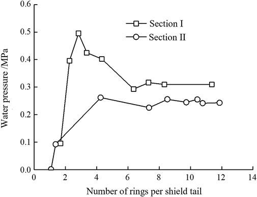
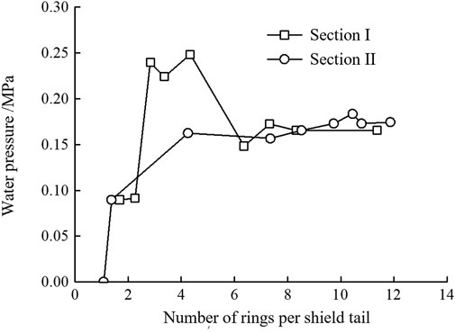
According to Figure 10, it is clear that the two measured sections located in B2 are essentially located at the top of the tunnel and field measurements can be used to obtain the distributed changes in the pressure of water and soil in the outer B2 section at locations I and II as shown in Figures 11, 12. It can be seen that the initial water pressure of section II is higher than that of section I, which is mainly due to the different testing time of the two initial water pressures. Due to the limitation of on-site installation and testing conditions, the initial water pressure of section II is measured after the shield tail passes through about two ring segments. At this time, the underground water is affected by grouting and surrounding rock deformation, which will produce a certain water pressure on the outside of the segment. The initial water pressure of section I is measured when the shield tail almost passed section I, and the water pressure outside the segment is almost zero. After water and soil loading had essentially stabilized, the total soil pressure at the top of the tunnel in Section I was 0.309 MPa, the water pressure was 0.144 MPa and the effective soil pressure was 0.165 MPa. The total soil pressure at the top of the tunnel in Section II was 0.243 MPa, the water pressure was 0.174 MPa and the effective soil pressure was 0.068 MPa.
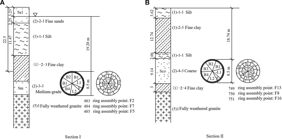
FIGURE 10. Stratum distribution of each monitoring section (unit: m). (A) Section I, (B) Section II.
5.3 Theoretical calculations and comparative analysis
It is rather difficult to make a direct comparison between the water and soil pressures at the top of the tunnel in Sections I and II. The following formula can be used to find a weighted average of the physical parameters of the soil strata above the tunnel to achieve an effective simplification of the conditions of the strata where these sections of the tunnel lie:
where x is the weighted average of the physical parameters of the soil body, xi is the value of the physical parameter at strata i and hi is the thickness of strata i.
The strata above the top of the tunnel was selected to perform a weighted calculation. Segment I is located in strata completely below the water level with separate strata of coarse sand, silt and fine clay. Some of the strata above the tunnel in Segment II are located above the water level and require separate calculations. The strata located below the water level are comprised of fine clay, silt and fine sand. The strata above the water level are comprised of fine sand. The results of a weighted calculation of the physical parameters of the strata of segments I and II are shown in Table 2.
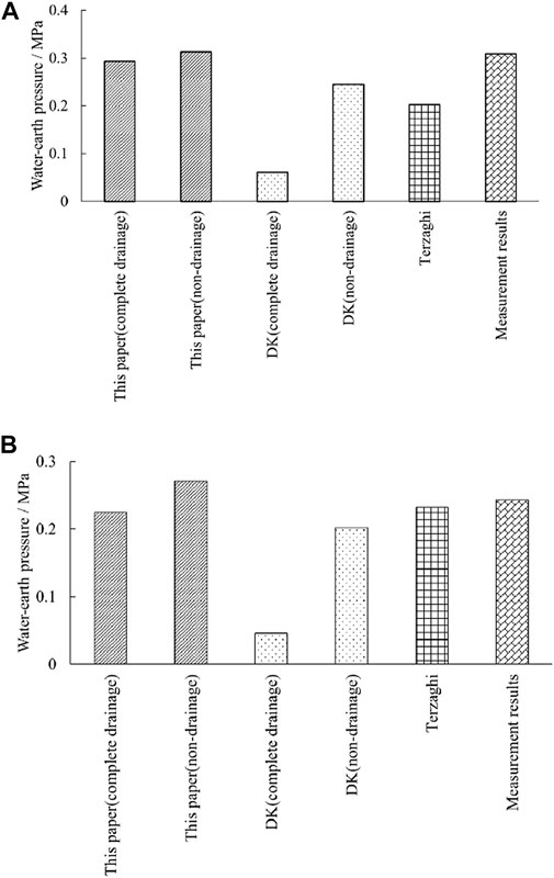
Based on the aforementioned parameters for the strata, different methods, including the Terzaghi method which does not take into consideration the impact of groundwater seepage, were used to perform a predictive analysis of the value of the water and soil pressure at the top of the tunnel. Calculations were performed according to the total stress method. The values for the water and soil pressure at the top of the tunnel obtained through these methods are shown in Table 3 and Figure 13. From an analysis of Figure 13, it is clear that the results from actual field measurements fall between the results of the fully-drained and non-drained conditions proposed in this paper while the results from calculations using the Dimitrios (2007) and Terzaghi methods have a small trend. For this project, the largest margin of error for the results obtained through this paper’s calculation method is 5.17% while those of the DK and Terzaghi methods are nearly 80% and 34.63%, respectively. This shows that the calculation method proposed by this paper has good precision and validity and is able to effectively predict the water and soil load on the top of the tunnel.
6 Conclusion
The water and soil load on the top of the tunnel is an important parameter for the design of shield tunnels. This paper employs a theoretical analysis to construct a model for the water and soil load on the top of the marine segment of a shield tunnel under the conditions of long-term water seepage and applies it to evaluate the water and soil pressure on the Maliuzhou Waterway section of the Hengqin Tunnel. The following primary conclusions were obtained.
1) The analytical model established by this paper for the water and soil load on the top of the tunnel is able to factor the effects of seepage force under conditions of long-term water seepage. Through a comparative analysis with actual field measurements, the Terzaghi total stress method, the DK effective stress method and other calculated results, it is clear that the margin of error for the results using this paper’s calculation method is least, thus verifying the validity of our method.
2) A type of analytical model was established for the coefficient of lateral earth pressure that takes into consideration the principal stress arch effect. A verification through a comparative analysis with existing models indicates that this paper’s model for the coefficient of lateral earth pressure is valid. Moreover, this paper reveals that as the angle of internal friction of the body of soil increases, the coefficient of lateral earth pressure first decreases then increases primarily due to the influence of the developing soil arching effect.
3) An impact analysis of relevant parameters shows that the water and soil load at the top of the tunnel has a positive correlation with the tunnel’s depth-diameter ratio with a rate of increase that gradually falls off; it has a positive linear correlation with the density of the soil body and the water head at the outside of the shield segment and a negative linear correlation with the seepage volume per unit width.
Data availability statement
The original contributions presented in the study are included in the article/supplementary material, further inquiries can be directed to the corresponding author.
Author contributions
ZZ: Conceptualization, Methodology, Software. LC: Data curation, Writing—Original draft preparation. LMC: Software, Validation. QS: Writing—Reviewing and Editing.
Funding
The authors acknowledge the financial support provided by the National Science Foundation of China (Grant No. U21A20159, No. 52279118, No. 52009129).
Conflict of interest
The authors declare that the research was conducted in the absence of any commercial or financial relationships that could be construed as a potential conflict of interest.
Publisher’s note
All claims expressed in this article are solely those of the authors and do not necessarily represent those of their affiliated organizations, or those of the publisher, the editors and the reviewers. Any product that may be evaluated in this article, or claim that may be made by its manufacturer, is not guaranteed or endorsed by the publisher.
References
Bi, J., Liu, P., and Gan, F. (2020). Effects of the cooling treatment on the dynamic behavior of ordinary concrete exposed to high temperatures. Constr. Build. Mater. 248, 118688. doi:10.1016/j.conbuildmat.2020.118688
Bi, J., Tang, J. C., and Wang, C. L. (2022). Crack coalescence behavior of rock-like specimens containing two circular embedded flaws[J]. Lithosphere 2022, 9498148. doi:10.2113/2022/9498148
Chen, K., and Peng, F. (2018). An improved method to calculate the vertical Earth pressure for deep shield tunnel in Shanghai soil layers. Tunn. Undergr. Space Technol. incorporating Trenchless Technol. Res. 75 (5), 43–66. doi:10.1016/j.tust.2018.01.027
Cui, L., Zheng, J., Zhang, R., and Dong, Y. (2015a). Elasto-plastic analysis of a circular opening in rock mass with confining stress-dependent strain-softening behaviour. Tunn. Undergr. Space Technol. 50, 94–108. doi:10.1016/j.tust.2015.07.001
Cui, L., Zheng, J., Zhang, R., and Lai, . (2015b). A numerical procedure for the fictitious support pressure in the application of the convergenceconfinement method for circular tunnel design. Int. J. Rock Mech. Min. 78, 336–349. doi:10.1016/j.ijrmms.2015.07.001
Cui, L., Zheng, J., Dong, Y., Zhang, B., and Wang, A. (2017). Prediction of critical strains and critical support pressures for circular tunnel excavated in strain-softening rock mass. Eng. Geol. 224, 43–61. doi:10.1016/j.enggeo.2017.04.022
Cui, L., Sheng, Q., Zheng, J., Cui, Z., Wang, A., and Shen, Q. (2019). Regression model for predicting tunnel strain in strain-softening rock mass for underground openings. Int. J. Rock Mech. Min. 119, 81–97. doi:10.1016/j.ijrmms.2019.04.014
Dimitrios, K., and Wagner, P. (2007). Groundwater ingress to tunnels – the exact analytical solution. Tunn. And Undergr. Space Technol. 22 (1), 23–27. doi:10.1016/j.tust.2006.02.001
Dong, Y., Cui, L., and Zhang, X. (2022). Multiple-GPU parallelization of three-dimensional material point method based on single-root complex. Int. J. Numer. Methods Eng. 123 (6), 1481–1504. doi:10.1002/nme.6906
Du, C., and Wang, M. (2011). Tan Z. Analytical solution of seepage field in underwater tunnel and its application[J]. Chin. J. Rock Mech. Eng. 30 (2), 3567–3573.
Fan, N., Jiang, J., You-kou, D., Guo, L., and Song, L. (2022). Approach for evaluating instantaneous impact forces during submarine slide-pipeline interaction considering the inertial action. Ocean. Eng. 245, 110466. doi:10.1016/j.oceaneng.2021.110466
Fernandez, G., and Moon, J. (2008). Excavation-induced hydraulic conductivity reduction around a tunnel – Part 1: Guideline for estimate of ground water inflow rate:guideline for estimate of ground water inflow rate[J]. Tunn. And Undergr. Space Technol. 25 (5), 560–566. doi:10.1016/j.tust.2010.03.006
Fu, H., Li, J., and Cheng, G. (2021). Prediction of tunnel water inflow in fault affected area based on conformal mapping[J]. J. Huazhong Univ. Sci. Technology:Natural Sci. Ed. 49 (1), 86–92. doi:10.13245/j.hust.210115
Handy, R. (1985). The arch in soil arching. J. Geotechnical Eng. 111 (3), 302–318. doi:10.1061/(asce)0733-9410(1985)111:3(302)
He, X., Zhou, X., and Guo, X. (2020). Analysis of non-Darcy seepage field and stress field of surrounding rock strengthened by grouting in deep buried tunnel[J]. China J. Highw. Transp. 33 (12), 200–211. doi:10.19721/j.cnki.1001-7372.2020.12.016
Koyama, Y. (2003). Present status and technology of shield tunneling method in Japan. Tunn. Undergr. Space Technol. 18 (2), 145–159. doi:10.1016/s0886-7798(03)00040-3
Kyung-Ho, P., Owatsiriwong, A., and Lee, J. G. (2008). Analytical solution for steady-state groundwater inflow into a drained circular tunnel in a semi-infinite aquifer: A revisit:a revisit[J]. Tunn. Undergr. Space Technol. 23 (2), 206–209. doi:10.1016/j.tust.2007.02.004
Lei, S. (1997). An analytical solution for steady flow into a ttonnel. Ground Water 37 (1), 23–26. doi:10.1111/j.1745-6584.1999.tb00953.x
Li, C. (2014). Research on calculation method of shield tunnel construction loosening Earth pressure[J]. Chin. J. Geotechnical Eng. 36 (9), 1714–1720. doi:10.11779/CJGE201409019
Li, C., Wang, S., and Wang, C. (2020a). Back analysis of load of large under water shield tunnel based on measured internal force[J]. China Civ. Eng. J. 53 (3), 103–113. doi:10.15951/j.tmgcxb.2020.03.012
Li, L., Yang, J., and Gao, C. (2020b). Analytical study on seepage field of tunnels with external drainage considering effect of grouting rings[J]. Chin. J. Geotechnical Eng. 42 (1), 133–141. doi:10.11779/CJGE202001015
Li, X., Zhou, S., and Gong, Q. (2015). Evaluation of the action mode of Earth pressure around large-section, deep-buried, high-pressure metro shield tunnel[J]. Rock Soil Mech. 36 (5), 1415–1420. doi:10.16285/j.rsm.2015.05.025
Liu, G., Zheng, F., Jia, L., Jia, Y., John Zhang, X. c., Hu, F., et al. (2019a). Interactive effects of raindrop impact and groundwater seepage on soil erosion. J. Hydrology 578, 124066. doi:10.1016/j.jhydrol.2019.124066
Liu, J., Zhao, Y., Tan, T., Zhang, L., Zhu, S., and Xu, F. (2022). Evolution and modeling of mine water inflow and hazard characteristics in southern coalfields of China: A case of meitanba mine. Int. J. Min. Sci. Technol. 32 (003), 513–524. doi:10.1016/j.ijmst.2022.04.001
Liu, Q., Pan, J., and Jin, F. (2019b). Study on analytic solution for seepage field of near-sea tunnel[J]. J. Beijing Jiaot. Univ. 43 (4), 18–28. doi:10.11860/j.issn.1673–0291.20180035
Maleki, M. (2018). Groundwater Seepage Rate (GSR); a new method for prediction of groundwater inflow into jointed rock tunnels. Tunn. Undergr. Space Technol. 71, 505–517. doi:10.1016/j.tust.2017.10.006
Mohamed, E. T. (2010). Helmholtz evolution of a semi-infinite aquifer drained by a circular tunnel. Tunn. Undergr. Space Technol. 25 (1), 54–62. doi:10.1016/j.tust.2009.08.005
Wan, T., Li, P., and Zheng, H. (2019). An analytical model of loosening Earth pressure in front of tunnel face for deep-buried shield tunnels in sand[J]. Comput. Geotechnics 115 (11), 103170.
Wang, D., He, S., and Liu, X. (2019a). Study on the influence of stratum progressive arching on the overburden Earth pressure of shallow tunnel[J]. Rock Soil Mech. 40 (6), 2311–2322. doi:10.16285/j.rsm.2018.1475
Wang, J., Yuan, D., and Jin, D. (2019b). Study on calculation model of shield tunnel loosening Earth pressure under steady seepage conditions[J]. J. Tianjin University:Natural Sci. Eng. Technol. Ed. 52 (1), 92–98. doi:10.11784/tdxbz201902019
Wang, J., Yuan, D., and Wang, T. (2020). Calculation model for loosening Earth pressure of the deeply-buried shield tunnel based on the influence of partial leakage[J]. China Civ. Eng. J. 53 (1), 105–111. doi:10.15951/j.tmgcxb.2020.s1.018
Wei, Z., and Zhu, Y. (2021). A theoretical calculation method of ground settlement based on a groundwater seepage and drainage model in tunnel engineering. Sustainability 13 (5), 2733. doi:10.3390/su13052733
Xiao, M., Feng, K., and Li, C. (2019). A method for calculating the surrounding rock pressure of shield tunnels in compound strata[J]. Chin. J. Rock Mech. Eng. 38 (9), 1836–1847. doi:10.13722/j.cnki.jrme.2019.0045
Xu, C., Liang, L., and Chen, Q. (2018). Research on loosening Earth pressure considering the patterns of stress distribution in loosening zone[J]. Rock Soil Mech. 39 (6), 1927–1934. doi:10.16285/j.rsm.2016.2093
Yu, L., Lyu, C., Wang, M., and Xu, T. (2019). Three-dimensional upper bound limit analysis of a deep soil-tunnel subjected to pore pressure based on the nonlinear Mohr-Coulomb criterion. Comput. Geotechnics 112 (9), 293–301. doi:10.1016/j.compgeo.2019.04.025
Zhang, B., Wang, Q., and Lu, X. (2018). Analytical solution for non-Darcian seepage field of a shallow circular tunnel in soft soil[J]. Rock Soil Mech. 39 (12), 4377–4384. doi:10.16285/j.rsm.2017.0882
Zhang, D., Liu, Z., and Shen, G. (2019). Measurement of Earth pressure of shallow buried tunnel with super large diameter and applicability evaluation of calculation method[J]. Rock Soil Mech. 40 (1), 91–98. doi:10.16285/j.rsm.2018.2055
Zhang, F., Fu, D., and Yang, G. (2002). Shield tunnel construction manual[M]. Beijing: Peoples Communications Press, 189–201.
Zhang, H., Zhang, P., Zhou, W., Dong, S., and Ma, B. (2016). A new model to predict soil pressure acting on deep burial jacked pipes. Tunn. Undergr. Space Technol. incorporating Trenchless Technol. Res. 60 (11), 183–196. doi:10.1016/j.tust.2016.09.005
Zhang, Z., Wang, J., and Zhao, Q. (2020). Analytical solution of head distribution on tunnel structure adjacent water-filled fault in water-enriched mountain region[J]. Chin. J. Rock Mech. Eng. 39 (2), 3378–3394. doi:10.13722/j.cnki.jrme.2019.0920
Zhao, Y., Tang, J., and Chen, Y. (2017a). Hydromechanical coupling tests for mechanical and permeability characteristics of fractured limestone in complete stress–strain process[J]. Environ. Earth Sci. 76, 1–18. doi:10.1007/s12665-016-6322-x
Zhao, Y., Tang, J., and Chen, Y. (2017b). Numerical analysis of karst water inrush and a criterion for establishing the width of water-resistant rock pillars[J]. Environ. Earth Sci. 36, 508–519. doi:10.1007/s10230-017-0438-4
Keywords: tunnel engineering, terrestrial and marine shield tunnel, water seepage, water and soil load, soil arching effect, coefficient of lateral earth pressure
Citation: Zhu Z, Chang L, Cui L and Sheng Q (2023) A method of calculating water and soil loading on top of shallow shield tunnels near water areas. Front. Earth Sci. 10:1097216. doi: 10.3389/feart.2022.1097216
Received: 13 November 2022; Accepted: 23 December 2022;
Published: 13 January 2023.
Edited by:
Chong Xu, Ministry of Emergency Management, ChinaReviewed by:
Danqing Song, Tsinghua University, ChinaYanlin Zhao, Hunan University of Science and Technology, China
Jing Bi, Guizhou University, China
Yong Fan, China Three Gorges University, China
Copyright © 2023 Zhu, Chang, Cui and Sheng. This is an open-access article distributed under the terms of the Creative Commons Attribution License (CC BY). The use, distribution or reproduction in other forums is permitted, provided the original author(s) and the copyright owner(s) are credited and that the original publication in this journal is cited, in accordance with accepted academic practice. No use, distribution or reproduction is permitted which does not comply with these terms.
*Correspondence: Lan Cui, bGN1aUB3aHJzbS5hYy5jbg==
 Zeqi Zhu
 Liuming Chang
 Lan Cui
 Qian Sheng