 Yulin Peng1,2
 Shan Dong
95% of researchers rate our articles as excellent or good
Learn more about the work of our research integrity team to safeguard the quality of each article we publish.
Find out more
ORIGINAL RESEARCH article
Front. Earth Sci. , 17 January 2023
Sec. Geohazards and Georisks
Volume 10 - 2022 | https://doi.org/10.3389/feart.2022.1026310
This article is part of the Research Topic Advanced Application of Deep Learning, Statistical Modelling, and Numerical Simulation on Geo-Environmental Hazards View all 59 articles
The mechanism of seismic-induced bedding rock landslide is distinct from that of slope instability/landslide in normal gravity conditions; their failure modes are mainly characterized by vibration deterioration effect of rock mass structural plane due to a seismic loading, which has a significant effect on the stability of the bedding rock landslide. Several advanced methods have been proposed to assess earthquake-induced bedding rock landslide. However, the quantitative evaluation of the vibration deterioration effect of structural plane, along with its application in the dynamic stability analysis of bedding rock slopes, remains a challenging topic that requires further study. In this study, on the basic of the analysis of the cyclic shear condition and the cyclic shear test of the structural plane, the expressions to calculate the dilatancy angle and basic friction angle of structural plane under cyclic shear loading are studied. A deterioration formula for structural plane shear strength is proposed, which fully considers the deterioration effect during cyclic shear. Furthermore, a new calculating method of the seismic-induced permanent displacement of the bedding rock landslide, which introduces the deterioration effect of the structural plane, is developed. A case study was used to compare the permanent displacement calculated with the proposed method with those obtained using the Newmark and Qi methods, which demonstrates the effectiveness and applicability of the proposed method.
When the magnitude of an earthquake exceeds Ms 4.0, landslides can be induced in sensitive areas; when the magnitude of an earthquake exceeds Ms 6.0, many landslides can be induced simultaneously (Keefer 1984; Rodríguez et al., 1999; Keefer 2000). Larger earthquakes can induce thousands of landslides over a wide area. For example, the Wenchuan Ms 8.0 earthquake in China triggered nearly 200,000 landslides, making it the largest, densest, widest, and most catastrophic seismic-induced landslide events caused by a single earthquake ever recorded. Bedding rock landslide is a common type of rock landslide, and is controlled by the interlayer structural planes of the rock mass. When subjected to an earthquake or dynamic loads, such slopes are prone to the occurance of overall bedding slip. In recent years, earthquakes have induced many bedding rock landslides, such as the Daguangbao and Tangjiashan landslides caused by the 2008 Wenchuan earthquake (Ms 8.0) in China (Burchfiel et al., 2008; Hu et al., 2009; Huang and Li, 2009; Cui et al., 2021), and the Arato-sawa landslide caused by the 2008 Iwate-Miyagi Naoriku earthquake (Ms 7.0) in Japan (Moriya et al., 2010; Ryoichi et al., 2010; Setiawan et al., 2016). These seismic-induced landslides lead to serious losses of life and property. Therefore, the study of seismic-induced bedding rock landslide is of great and practical significance.
When the seismic loading is strong, the cyclic shear phenomenon occurs along the interlayer structural plane and the slipping body consequently moves along the structural plane. As demonstrated in Figure 1, taking the horizontal seismic acceleration as an example, when the upward component of the horizontal seismic force along the interlayer structural plane (
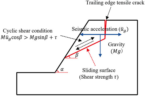
FIGURE 1. Condition of cyclic shear under horizontal seismic acceleration.
Wang and Zhang (1982) found that the movement rate and cumulative displacement of rock blocks have a direct deterioration effect on the dynamic frictional coefficient, and initially tried to incorporate the degradation effect of the structural plane into the calculation method of the sliding displacement of rock slopes. Crawford and Curran (1981, 1982) also proposed a method of calculating the seismic permanent displacement of rock slope introducing the deterioration effect of cumulative displacement and motion velocity on structural plane. Based on the work by Wang and Zhang (1982) and Crawford and Curran (1981, 1982), Qi (2007) proposed a seismic permanent displacement calculation method of planar sliding and wedge sliding problem considering the effect of shear rate and cumulative relative displacement on the deterioration of structural surface roughness. Through the experimental analysis of direct shear experiment and shaking table test, Bakun-Mazor et al. (2012) found that, under the strong ground motion, the dynamic analysis of rock slopes should consider the effect of shear velocity on the friction force of the structural plane. By integrating the influencing factors of vibration wear and relative velocity, Ni et al. (2013) presented mathematical expressions for the vibration degradation effect of a structural face through experimental research, and applied them to the calculation of the dynamic stability analysis of rock slopes using numerical simulation method. Liu et al. (2016) found that the shear strength of structural plane was reduced due to the wear of wave angle and relative velocity between rock blocks during the process of earthquake action, and a mathematical model to calculate the deterioration of the structural plane and a numerical calculation procedure were established. Based on the Newmark and residual thrust methods, Cen (2017) proposed a theoretical model and dynamic analysis with time-history, considering the entire shear process deterioration effect of bedding rock landslide. Dong et al. (2020) proposed deterioration formulas for structural plane shear strength parameters under cyclic shear loading, and on the basis of the cyclic structural plane shear test, they proposed a calculation method for rock landslide displacement by introducing the deterioration effect of the structural plane. However, existing researches on bedding rock landslide stability calculation introducing the effect of structural plane degradation have not yet yielded a definitive and well-recognized method, and the analysis of the dynamic stability of bedding rock landslide with consideration of structural plane vibration degradation required in-depth study.
In conclusion, the effect of seismic loading on the stability of bedding rock landslide lies in the influence of seismic loading on inertial force and the deterioration effect of seismic loading on shear strength (frictional coefficient) of interlayer structural plane. The present study, firstly, investigated the shear-strength deterioration effect of a structural plane. Then, based on the simplified dynamic calculation model of the bedding-rock landslide and introducing the vibration-induced deterioration effect of the structural plane, a new calculating method of the seismic-induced permanent displacement of the bedding rock landslide is further developed. And the motivation of this study is to further improve the understanding of seismic-induced landslide mechanisms by means of a relatively systematic investigation into the dynamic characteristics, instability mechanisms, and stability evaluation methods of bedding-rock landslides under seismic loading.
It is difficult to obtain and sample natural structural planes with complex surface undulations, and the consistency related to the sampling cannot be guaranteed. However, it has been proved that it is feasible to use rock structure samples prepared from cement mortar and other similar materials to replace the surface morphology and undulation of natural structural planes (Einstein et al., 1983; Plesha, 1987; Yang et al., 2001; Jafari et al., 2003; Li et al., 2008; Du et al., 2011). When using simulated structural planes to replace natural structural planes for direct shear tests, the wear degree and failure mode of simulated structural planes are similar to those of natural structural planes. The existing research results (Ladanyi and Archambault 1970; Yang et al., 2001; Jafari et al., 2003; Shen and Zhang, 2010) show that although there are differences between the sawtooth structural plane and the natural structural plane, the shear test with sawtooth structural plane is usually reasonable and can catch the surface morphology and undulations of the structural plane. Using cement mortar as the similar material, Liu et al. (2011) prepared sawtooth structural plane specimens with different initial undulant angles of 16°, 25°, 33°, 40°and 45°, respectively. Using an RJDT-A shear testing device (Figure 2), Liu et al. (2011) carried out cyclic shear tests on structural planes under four kinds normal stresses of 0.8, 1.6, 2.4, and 3.2 MPa, respectively. Due to the limitations of the RJDT-A shear testing device, the relative maximum shearing displacement was set to be ±10 mm, and the cyclic number was set to be 10 repetitions. In the shear process, the lower shear box remains stationary, and the specimen is sheared by the horizontal motion of the upper shear box. A single cyclic shear process of the rock mass structural plane is illustrated in Figure 3.
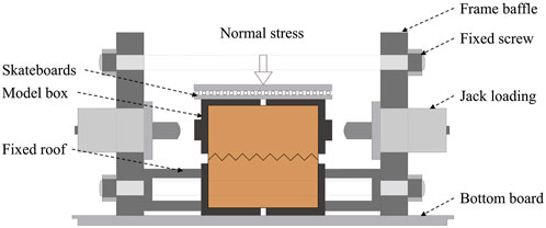
FIGURE 2. Schematic view of RJDT-A shear box.
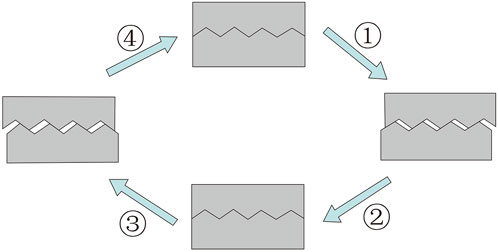
FIGURE 3. A single cyclic shear process of the rock mass structural plane.
Introducing the shear strength ratio
The shear strength ratio
Figure 4 demonstrates the variation of shear strength ratios
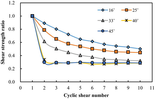
FIGURE 4. Variation of shear strength ratio (
When the shear movement of rock mass occurs, the shear resisting force mainly consists of the undulations of the structural plane and the friction of the contact sections:
where
On the basis of many direct shear tests on the rough structural plane, Barton and Choubey (1977) proposed to replace the undulant angle with the dilatancy angle:
where
Furthermore, Barton (1973) further proposed the following shear strength equation for structural plane:
where
Then, Eqs. 3, 4 can be combined as follows:
And after nth cyclic shear, the friction angle of the structural plane can be obtained:
where n denotes the cyclic shear number,
So, after nth cyclic shear, the peak shear strength of structural plane can be obtained:
According to the strength characteristic test of structural plane under different shear velocity, Li et al. (2006) concluded that the peak shear strength of structural plane decreases with the increase of relative shear velocity. Thus, an exponential decay functional relationship exists between the peak strength and the relative shear velocity. According to the research of Wang and Zhang (1982) and Li et al. (2006), Liu (2017) further proposed to express the relative velocity coefficient as follows:
where
Therefore, combining Eqs. 7, 8, the shear strength of the structural plane introducing the relative shear velocity effect can be obtained as follows:
According to Eq. 9, the key to determining the shear strength of a structural plane during the cyclic shear is to derive variation laws of the dilatancy angle and the basic friction angle. Therefore, this section will focus on the analysis of the variation laws of the dilatancy angle and the basic friction angle during the cyclic shear.
Figure 5 demonstrates the variation of the average dilatancy angle with cyclic shear number for the cases of different initial undulant angles (Liu et al., 2013a). It can be found that with the increase of initial undulant angle, the dilatancy angle at the first cyclic shear of the structural plane increases firstly and then decreases (16°<25°<33°,16°>40°>45°). This is mainly due to the difference of shear failure modes between structural planes with high undulant angle and those with medium undulant angle, and the initial undulant angles of the 40° and 45° structural planes are more serious. On the whole, for structural planes with different initial undulant angles, the dilatancy angle gradually decrease, first rapidly, then more gradually and incline be stable slowly with the increase of cyclic shear number.
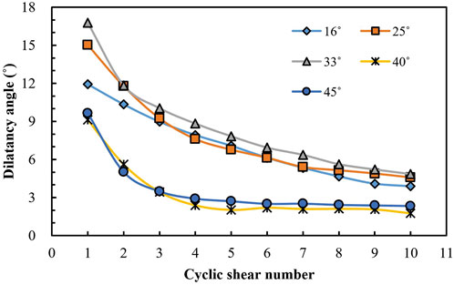
FIGURE 5. Variation of the average dilatancy angle with cyclic shear number with five kinds of initial undulant angles (Liu et al., 2013a).
On the basis of above experimental results, Liu et al. (2013b) further found that there exists a negative exponential distribution relationship between the average dilatancy angle of the structural plane and the cyclic shear number, and the following expression is proposed:
where
The wear coefficient
When
Therefore,
Based on Liu et al. (2013b) study, under the same uniaxial compressive strength of the intact rock
where parameters a, b, c, and d denote constants that are linked to uniaxial compressive strength of the intact rock
Based on Dong et al. (2020), the average shear dilatancy angle of the structural plane can reflect the degradation of undulations during the cyclic shearing, and the basic frictional angle and the average shear dilatancy angle have the same variation trend. Thus, the following equation exists:
where
According to Eq. 16, the basic frictional angle of the structural plane after the nth cyclic shear can be obtained:
where
The residual equivalent frictional angle (
where
Thus, according to Eqs. 17, 19, the expression of basic friction angle
A simplified dynamic calculation model of a bedding rock slope is illustrated in Figure 6, assuming that the potential sliding body produces unstable sliding along the rock stratum of the ith layer, di denotes the exposed length of ith rock stratum, α denotes the slope gradient, β denotes the dip angle of the rock stratum,
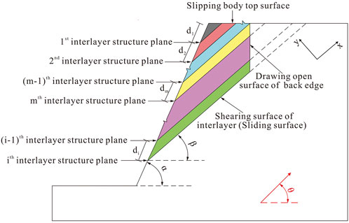
FIGURE 6. Generalized diagram of dynamic model of bedding rock slope.
It should be noted that the quadrilateral area is composed of slope surface, sliding surface, slipping body top surface, and tensile crack surface of back edge of the rock slope. And the area of potential sliding body is determined by:
The gravity of the potential sliding body in layer i is
where
According to the force equilibrium analysis in dynamic analysis model, in the Y direction
and in the X direction
where T denotes the parallel (shear) reaction forces, N denotes the orthogonal (normal) reaction forces,
For the bedding rock landslide, the influence of cohesion (c) is mainly focused on the first cyclic shear process. Once the sliding mass generates cyclic shear under strong ground motion, the influence of cohesion (c) on shear strength is commonly ignored (Dong et al., 2020). The critical acceleration
The safety factor
Based on Figure 6, the X-direction vibration balance equation can be expressed as follows:
where M is the mass of the potential sliding body, and
And according to Eqs. 24, 28, 29 the acceleration of the potential sliding body can be expressed as follows:
After obtaining the dilatancy angle and basic friction angle after nth cyclic shear, the calculation procedures of permanent displacement are as follows:
1) The seismic acceleration
2) When the seismic acceleration
3) The occurrence of sliding depends on whether
4) Repeating the step (3) until the nth time-history, and finally obtaining the permanent displacement
It is very difficult to find the monitoring data of sliding displacement of bedding rock slope under seismic loading. Thus, in order to illustrate the effectiveness and applicability of the proposed calculating method for permanent displacement, referring to the experimental research results of Liu et al. (2013b), a calculation case study was conducted. In the case study, the main parameters are as follows: the normal stress was 1.6 MPa, the basic friction angle was 30.5°, the initial undulant angle was 16°, the uniaxial compressive strength of the intact rock was 30 MPa, the residual shear strength was 0.798 MPa, the residual dilatancy angle was 7.744°, and the cyclic shear number n=10.
Based on dynamic analysis model in Figure 6, assuming that the slope gradient was 30°, the dip angle of rock stratum was 15°, the weight of rock mass was 23 kN/m3, the thickness of each layer of the rock stratum was equal, the length of the exposed surface of each layer was 10 m. Under the seismic loading, the average relative shear velocity
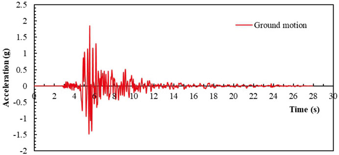
FIGURE 7. Seismic acceleration used in the case study.
Based on the experimental results of wear coefficient of the average dilatancy angle (
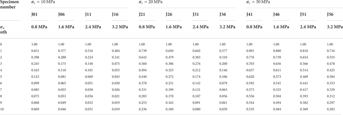
TABLE 1. Experimental results of
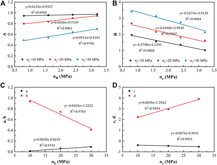
FIGURE 8. Fitting relationships of main parameters. (A) Fitting relationships between A and
Based on Eqs. 31, 32, after 10-th shear cycles, the values of parameters A and B were 0.583 and 3.033, respectively. According to Eqs. 13, 20, the variations of the dilatancy angle and basic friction angle with the increase of cyclic shear number were obtained (Figure 9). The dilatancy angle and basic friction angle gradually decreased and tended to be stable with the increase of the cyclic shear number. After 10-th cyclic shear, the calculated final dilatancy angle was 7.015°. From Eq. 20, the basic friction angle after 10-th cyclic shear was 17.728°.
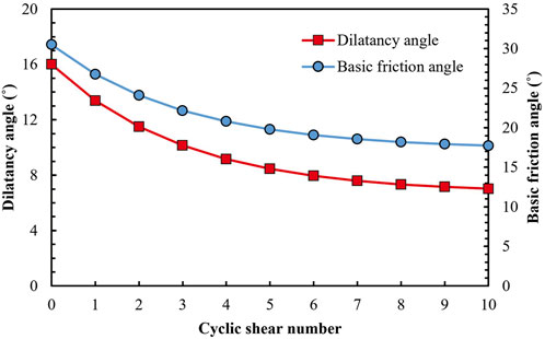
FIGURE 9. Variations of dilatancy angle and basic friction angle with cyclic shear number.
After obtaining the dilatancy angle and basic friction angle, based on the analysis steps of permanent displacement, the variations of critical acceleration and permanent displacement with the cyclic shear number are obtained respectively (Figure 10), where the number of cycle shear is 0, indicating that the deterioration effect of the structural plane is not considered. With the increase of the cyclic shear number, the critical acceleration decreases gradually, especially when cyclic shear number is greater than 5, the critical acceleration decreases slowly and tends to be stable. The permanent displacement increases gradually with the increase of cyclic shear number. And the permanent displacement of the slope is obtained to be 0.015 m when the deterioration effect is not considered. Before the 5-th cyclic shear, the permanent displacement increases linearly with the cyclic shear number, and then the permanent displacement increases slowly and gradually tends to be stable, and the calculated final permanent displacement is 0.420 m after 10-th cyclic shear.
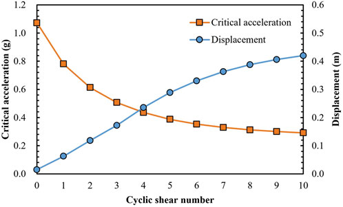
FIGURE 10. Variations of critical acceleration and permanent displacement with the cyclic shear number.
Newmark (1965) introduced seismic loading into rock slope stability analyses and further proposed Newmark sliding rigid block method. For the Newmark method, the critical acceleration is:
where
Based on the vibration degradation law of the undulant angle by using the research results of Plesha (1987), Qi (2007) proposed a permanent displacement calculation method of rock slope, in which the variation of undulant angle is:
where
In the Qi method, the basic friction angle
The initial critical acceleration
Considering the cumulative displacement and relative velocity effect, the expression of critical acceleration with displacement is proposed as follows:
where
And the acceleration of the sliding body is expressed as:
The seismic acceleration
The comparative calculation results of critical acceleration are presented in Table 2. The critical acceleration of the Newmark method is 0.613 g. For the Qi method, when
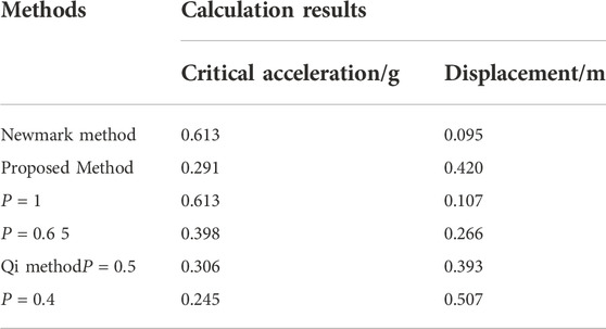
TABLE 2. Calculation results using different methods.
The calculation results of permanent displacement are shown in Table 2; Figure 11. In the proposed method, the cumulative displacement curve obtained is between those of the Qi method with p = 0.4 and p = 0.5, and in contrast the cumulative displacement is closer to the Qi method with p = 0.5. However, the permanent displacement obtained by Qi method and the proposed method is larger than that provided by the Newmark method, which illustrates that the deterioration effect of the structural plane has a significant effect on the calculation of permanent displacement, and the calculation methods that considers the deterioration effect are more conservative and reliable in terms of evaluating the stability of seismic-induced landslides.
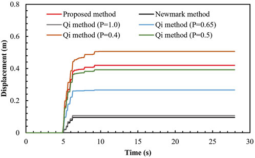
FIGURE 11. Permanent displacements obtained by different methods.
In this study, based on the analysis of the cyclic shear condition under seismic loading, a new method for calculating the permanent displacement of the bedding-rock landslide was proposed by introducing the degradation effect of structural plane, and the following main conclusions can be obtained:
1) When the upward component of the horizontal seismic force along the interlayer structural plane is greater than the resulatant force of the shear strength of the interlayer structural plane and the weight component of the sliding body, a cyclic shear mode of the slipping body will occur.
2) Under the cyclic shear loading, the deterioration of the structural plane mainly consists of the relative shear velocity effect, dilatancy angle degradation and basic frictional angle degradation.
3) To verify the effectiveness and applicability of the proposed calculating method for permanent displacement, using a case study, the calculated displacement results using the proposed method were compared with those obtained using the Newmark and Qi method. It was found that under seismic loading, the degradation effect of the structural plane has a direct effect on the permanent displacement and stability of the bedding rock landslide. The calculation method proposed in this paper potentially serves as reference for engineering design, calculation, and application.
The original contributions presented in the study are included in the article/Supplementary Material, further inquiries can be directed to the corresponding author.
YP and SD were responsible for the main manuscript writing and idea discussions; Other authors were responsible for the prepare the paper language, figures, and tables. All authors have reviewed and agreed to the published version of the manuscript.
The Fellowship of China Postdoctoral Science Foundation (Grant No. 2022M712949); the Open Fund Project of Badong National Observation and Research Station of Geohazards, China University of Geosciences (Grant No. BNORSG202210); the State Key Laboratory of Geohazard Prevention and Geoenvironment Protection of the Chengdu University of Technology Open Fund (Grant No. SKLGP 2019K010); the State Key Laboratory of Geohazard Prevention and Geoenvironment Protection of the Chengdu University of Technology Open Fund (Grant No. SKLGP 2020K015).
Author ZL was employed by the company Changjiang Institute of Survey, Planning, Design and Research Corporation.
The remaining authors declare that the research was conducted in the absence of any commercial or financial relationships that could be construed as a potential conflict of interest.
All claims expressed in this article are solely those of the authors and do not necessarily represent those of their affiliated organizations, or those of the publisher, the editors and the reviewers. Any product that may be evaluated in this article, or claim that may be made by its manufacturer, is not guaranteed or endorsed by the publisher.
Bakun-Mazor, D., Hatzor, Y. H., and Glaser, S. D. (2012). Dynamic sliding of tetrahedral wedge: The role of interface friction. Int. J. Numer. Anal. Meth. Geomech. 36 (3), 327–343. doi:10.1002/nag.1009
Barton, N. R., and Choubey, V. (1977). The shear strength of rock joints in theory and practice. Rock Mech. 10 (1-2), 1–54. doi:10.1007/bf01261801
Barton, N. R. (1973). Review of a new shear strength criterion for rock joints. Eng. Geol. 7 (4), 287–332. doi:10.1016/0013-7952(73)90013-6
Burchfiel, B. C., Royden, L. H., Hilst, R. D. V. D., Hager, B. H., Chen, Z., King, R. W., et al. (2008). A geological and geophysical context for the wenchuan earthquake of 12 may 2008, sichuan, people's Republic of China. Gsa Today 18 (7), 4–11. doi:10.1130/gsatg18a.1
Cen, D. (2017). Tensional rupture and low-friction initiation mechanism of bedding landslides triggered by mega-earthquakes. Chongqing: Chongqing University.
Crawford, A. M., and Curran, J. H. (1982). The influence of rate- and displacement-dependent shear resistance on the response of rock slopes to seismic loads. Int. J. Rock Mech. Min. Sci. Geomechanics Abstr. 19 (1), 1–8. doi:10.1016/0148-9062(82)90704-5
Crawford, A. M., and Curran, J. H. (1981). The influence of shear velocity on the frictional resistance of rock discontinuities. Int. J. Rock Mech. Min. Sci. Geomechanics Abstr. 18 (6), 505–515. doi:10.1016/0148-9062(81)90514-3
Cui, S., Pei, X., Jiang, Y., Wang, G., Fan, X., Yang, Q., et al. (2021). Liquefaction within a bedding fault: Understanding the initiation and movement of the Daguangbao landslide triggered by the 2008 Wenchuan Earthquake (Ms = 8.0). Eng. Geol. 295, 106455. doi:10.1016/j.enggeo.2021.106455
Dong, S., Feng, W., Yin, Y., Hu, R., and Zhang, G. (2020). Calculating the permanent displacement of a rock slope based on the shear characteristics of a structural plane under cyclic loading. Rock Mech. Rock Eng. 53 (53), 4583–4598. doi:10.1007/s00603-020-02188-y
Du, S., Hu, Y., Hu, X., and Guo, X. (2011). Comparison between empirical estimation by JRC-JCS model and direct shear test for joint shear strength. J. Earth Sci. 22 (3), 411–420. doi:10.1007/s12583-011-0193-6
Einstein, H. H., Veneziano, D., Baecher, G. B., and O’Reilly, K. J. (1983). The effect of discontinuity persistence on rock slope stability. Int. J. Rock Mech. Min. Sci. Geomechanics Abstr. 20 (5), 227–236. doi:10.1016/0148-9062(83)90003-7
Homand, F., Belem, T., and Souley, M. (2001). Friction and degradation of rock joint surfaces under shear loads. Int. J. Numer. Anal. Meth. Geomech. 25 (10), 973–999. doi:10.1002/nag.163
Hu, X., Huang, R., Shi, Y., Lu, X., and Wang, X. (2009). Analysis of blocking river mechanism of Tangjiashan landslide and dam-breaking mode of its barrier dam. Chin. J. Rock Mech. Eng. 28 (1), 181–189.
Huang, R., and Li, W. (2009). Development and distribution of geohazards triggered by the 5.12 Wenchuan Earthquake in China. Sci. China Ser. E-Technol. Sci. 52 (4), 810–819. doi:10.1007/s11431-009-0117-1
Hutson, R. W., and Dowding, C. H. (1990). Joint asperity degradation during cyclic shear. Int. J. Rock Mech. Min. Sci. Geomechanics Abstr. 27 (2), 109–119. doi:10.1016/0148-9062(90)94859-r
Indraratna, B., Welideniya, H. S., and Broen, E. T. (2005). A shear strength model for idealised infilled joints under constant normal stiffness (CNS). Geotech 55 (3), 215–226.
Indraratna, B., Haque, A., and Aziz, N. (1999). Shear behaviour of idealized infilled joints under constant normal stiffness. Geotechnique 49 (3), 331–355. doi:10.1680/geot.1999.49.3.331
Jafari, M. K., Hosseini, K. A., Pellet, F., Boulon, M., and Buzzi, O. (2003). Evaluation of shear strength of rock joints subjected to cyclic loading. Soil Dyn. Earthq. Eng. 23 (7), 619–630. doi:10.1016/s0267-7261(03)00063-0
Keefer, D. K. (1984). Landslides caused by earthquakes. Geol. Soc. Am. Bull. 95, 406–421. doi:10.1130/0016-7606(1984)95<406:lcbe>2.0.co;2
Keefer, D. K. (2000). Statistical analysis of an earthquake-induced landslide distribution the 1989 Loma Prieta, California event. Eng. Geol. 58 (3-4), 231–249. doi:10.1016/s0013-7952(00)00037-5
Ladanyi, B., and Archambault, G. (1970). “Simulation of shear behavior of a jointed rock mass,” in Proc.11th syrup. On rock mechanics: Theory and practice (New York: AIME), 105–125.
Li, B., Jiang, Y., Koyama, T., Jing, L., and Tanabashi, Y. (2008). Experimental study of the hydro-mechanical behavior of rock joints using a parallel-plate model containing contact areas and artificial fractures. Int. J. Rock Mech. Min. Sci. (1997). 45 (3), 362–375. doi:10.1016/j.ijrmms.2007.06.004
Li, H., Deng, J., Feng, P., Pu, C., Arachchige, D., and Cheng, Q. (2021a). Short-term nacelle orientation forecasting using bilinear transformation and ICEEMDAN framework. Front. Energy Res. 9, 780928. doi:10.3389/fenrg.2021.780928
Li, H., Deng, J., Yuan, S., Feng, P., and Arachchige, D. (2021b). Monitoring and identifying wind turbine generator bearing faults using deep belief network and EWMA control charts. Front. Energy Res. 9, 799039. doi:10.3389/fenrg.2021.799039
Li, H., Feng, H., and Liu, B. (2006). Study on strength behaviors of rock joint under different shearing deformation velocities. Rock Soil Mech. 25 (12), 2435–2440.
Li, H. (2022a). SCADA data based wind power interval prediction using LUBE-based deep residual networks. Front. Energy Res. 10, 920837. doi:10.3389/fenrg.2022.920837
Li, H. (2022b). Short-term wind power prediction via spatial temporal analysis and deep residual networks. Front. Energy Res. 10, 920407. doi:10.3389/fenrg.2022.920407
Liu, B., Li, H., and Liu, Y. (2013a). Experimental study of deformation behavior of rock jointsunder cyclic shear loading. Rock Soil Mech. 34 (09), 2475–2488.
Liu, B., Li, H., Liu, Y., and Xia, X. (2013b). Generalized damage model for asperity and shear strength calculation of joints under cycle shear loading. Chin. J. Rock Mech. Eng. 32 (2), 3000–3008. doi:10.3969/j.issn.1000-6915.2013.z2.003
Liu, B., Li, H., and Zhu, X. (2011). Experimental simulation study of strength deterioration of rock joints under cyclic shear loading. Chin. J. Rock Mech. Eng. 30 (10), 2033–2039.
Liu, X., Liu, Y., He, C., and Li, W. (2016). Dynamic stability analysis of the bedding rock slope considering the vibration deterioration effect of the structural plane. Bull. Eng. Geol. Environ. 77, 87–103. doi:10.1007/s10064-016-0945-8
Liu, Y. (2017). Study on cumulative damage evolution mechanism and stability of bedding rock slope in reservoir area under frequent microseismic. Chongqing: Chongqing University.
Mirzaghorbanali, A., Nemcik, J., and Aziz, N. (2014). Effects of shear rate on cyclic loading shear behaviour of rock joints under constant normal stiffness conditions. Rock Mech. Rock Eng. 47 (5), 1931–1938. doi:10.1007/s00603-013-0453-0
Moriya, H., Abe, S., Ogita, S., and Higaki, D. (2010). Structure of the large-scale landslide at the upstream area of Aratozawa Dam induced by the Iwate-Miyagi Nairiku earthquake in 2008. J. Jpn. Landslide Soc. 47 (2), 77–83. doi:10.3313/jls.47.77
Mroz, Z., and Giambanco, G. (2015). An interface model for analysis of deformation behaviour of discontinuities. Int. J. Numer. Anal. Methods Geomech. 20 (1), 1–33. doi:10.1002/(sici)1096-9853(199601)20:1<1::aid-nag799>3.0.co;2-l
Newmark, N. M. (1965). Effects of earthquakes on dams and embankments. Geotechnique 15 (2), 139–160. doi:10.1680/geot.1965.15.2.139
Ni, W., Tang, H., Liu, X., and Wu, Y. (2013). Dynamic stability analysis of rock slope considering vibration deterioration of structural planes under seismic loading. Chin. J. Rock Mech. Eng. 32 (3), 492–500. doi:10.3969/j.issn.1000-6915.2013.03.008
Papaliangas, T., Lumsden, A. C., Hencher, S. R., and Manolopoulou, S. (1990). Shear strength of modelled filled rock joints. Proc International Symposium on Rock Joints, Loen, 275–283. doi:10.1016/0148-9062(91)92234-p
Plesha, M. E. (1987). Constitutive models for rock discontinuities with dilatancy and surface degradation. Int. J. Numer. Anal. Methods Geomech. 11 (4), 345–362. doi:10.1002/nag.1610110404
Premadasa, W., Indraratna, B., Mizargobanali, A., and Oliveira, D. (2012). “Shear behaviour of rock joints under cyclic loading,” in Australia-New Zealand conference on geomechanics: Ground engineering in A changing world.
Qi, S. (2007). Evaluation of the permanent displacement of rock mass slope considering deterioration of slide surface during earthquake. Chin. J. Geotech. Eng. 29 (3), 452–457. doi:10.3321/j.issn:1000-4548.2007.03.024
Rodríguez, C. E., Bommer, J. J., and Chandler, R. J. (1999). Earthquake-induced landslides: 1980-1997. Soil Dyn. Earthq. Eng. 18 (5), 325–346. doi:10.1016/s0267-7261(99)00012-3
Ryoichi, Ohno., Shin-ichi, Yamashina., Takanari, Y. A. M. A. S. A. K. I., Tomofumi, K. O. Y. A. M. A., Fumitoshi, E. S. A. K. A., and Shikoh, K. A. S. A. I. (2010). Mechanisms of a large-scale landslide triggered by the earthquake in 2008: A study of arato-sawa landslide. J. Jpn. Landslide Soc. 47 (2), 84–90. doi:10.3313/jls.47.84
Setiawan, H., Sassa, K., Takara, K., Miyagi, T., and Fukuoka, H. (2016). Initial pore pressure ratio in the earthquake triggered large-scale landslide near aratozawa dam in miyagi prefecture, Japan. Procedia Earth Planet. Sci. 16, 61–70. doi:10.1016/j.proeps.2016.10.007
Shen, M., and Zhang, Q. (2010). Experimental study of shear deformation characteristics of rock mass discontinuities. Chin. J. Rock Mech. Eng. 29 (4), 713–719.
Souley, M., Homand, F., and Amadei, B. (1995). An extension to the Saeb and Amadei constitutive model for rock joints to include cyclic loading paths. Int. J. Rock Mech. Min. Sci. Geomechanics Abstr. 32 (2), 101–109. doi:10.1016/0148-9062(94)00039-6
Tulinov, R., and Molokov, L. (1971). “Role of joint filling material in shear strength of rocks,” in Symposium of international society of rock mechanics (Nancy.
Wang, S., and Zhang, J. (1982). Dynamic analysis of sliding stability of slope rock mass. Chin. J. Geol. 2, 162–170.
Yang, Z., Di, C., and Yen, K. (2001). The effect of asperity order on the roughness of rock joints. Int. J. Rock Mech. Min. Sci. (1997). 38 (5), 745–752. doi:10.1016/s1365-1609(01)00032-6
Zheng, B., Qi, S., Zhan, Z., Zou, Y., and Zhang, S. (2015). Effect of shear rate on the strength characteristics of rock joints. J. Earth Sci. Envir. 37 (5), 101–110.
Keywords: structural plane, deterioration effect, seismic-induced bedding rock landslide, dynamic analysis model, permanent displacement
Citation: Peng Y, Dong S, Lu Z, Zhang H and Hou W (2023) A method for calculating permanent displacement of seismic-induced bedding rock landslide considering the deterioration of the structural plane. Front. Earth Sci. 10:1026310. doi: 10.3389/feart.2022.1026310
Received: 23 August 2022; Accepted: 14 November 2022;
Published: 17 January 2023.
Edited by:
Shenghua Cui, Chengdu University of Technology, ChinaReviewed by:
Xiangbo Bu, Universitat Politecnica de Catalunya, SpainCopyright © 2023 Peng, Dong, Lu, Zhang and Hou. This is an open-access article distributed under the terms of the Creative Commons Attribution License (CC BY). The use, distribution or reproduction in other forums is permitted, provided the original author(s) and the copyright owner(s) are credited and that the original publication in this journal is cited, in accordance with accepted academic practice. No use, distribution or reproduction is permitted which does not comply with these terms.
*Correspondence: Shan Dong, ZG9uZ3NoYW5AY3VnLmVkdS5jbg==
Disclaimer: All claims expressed in this article are solely those of the authors and do not necessarily represent those of their affiliated organizations, or those of the publisher, the editors and the reviewers. Any product that may be evaluated in this article or claim that may be made by its manufacturer is not guaranteed or endorsed by the publisher.
Research integrity at Frontiers
Learn more about the work of our research integrity team to safeguard the quality of each article we publish.