 Kotaro Kojima
 Izuru Takewaki
94% of researchers rate our articles as excellent or good
Learn more about the work of our research integrity team to safeguard the quality of each article we publish.
Find out more
ORIGINAL RESEARCH article
Front. Built Environ. , 06 March 2025
Sec. Earthquake Engineering
Volume 11 - 2025 | https://doi.org/10.3389/fbuil.2025.1539299
This article is part of the Research Topic Behavior of Buildings under Seismic Sequences View all articles
A triple impulse is used as a mathematical model of forward-directivity inputs, which are fault-normal components of near-fault earthquake ground motions. In this paper, two types of the triple impulse input are employed. One is the triple impulse with the same time interval. The critical triple impulse of this sequence is defined as the triple impulse with the critical time intervals maximizing the displacement response, and the critical time intervals are necessary to be captured by changing the time intervals. The other is the triple impulse, with second and third impulses acting at zero-restoring force points. The elastic–plastic responses of single-degree-of-freedom (SDOF) systems with bilinear hysteresis and viscous damping under the two types of triple impulses are obtained by time-history response analysis and compared. Furthermore, approximate expressions are derived for the responses of the damped bilinear hysteretic SDOF system under the triple impulse (the latter triple impulse stated above), with impulses acting at the zero-restoring force timing. In response derivation, a quadratic function approximation of the damping force–displacement relationship and an energy balance approach are employed. The validity of the triple impulse as the model of the forward-directivity input and the accuracy of approximate expressions to the triple impulse (the latter triple impulse stated above) are checked by comparing them with responses under the equivalent three wavelets of sinusoidal waves and the Ricker wavelet.
Long-period and pulse-like earthquake ground motions with large amplitudes, called near-fault pulse-like ground motions, were recorded near earthquake source faults. The characteristics of these types of ground motions and their effect on damage to building structures have been studied in the previous works (for example, Bertero et al., 1978; Sasani and Bertero, 2000; Sakai et al., 2000; Alavi and Krawinkler, 2001; Alavi and Krawinkler, 2004; Mavroeidis and Papageorgiou, 2003; Mavroeidis et al., 2004; Makris and Black, 2004; Kalkan and Kunnath, 2006; Xu et al., 2007; Takewaki and Tsujimoto, 2011; Minami and Hayashi, 2013; Khaloo et al., 2015; Okazawa et al., 2018). Such near-fault pulse-like ground motions are broadly classified into two types depending on their input directions (Sasani and Bertero, 2000). One is the fling-step input with a fault-parallel component of the near-fault pulse-like ground motion, and the second is the forward-directivity input with a fault-normal component. The main part of these inputs can be represented by a few series of wavelets, and their mathematical models have been proposed to evaluate seismic responses of building structures to these inputs in many papers (Sasani and Bertero, 2000; Sakai et al., 2000; Alavi and Krawinkler, 2001; Alavi and Krawinkler, 2004; Mavroeidis and Papageorgiou, 2003; Makris and Black, 2004; Xu et al., 2007; Takewaki and Tsujimoto, 2011; Minami and Hayashi, 2013; Okazawa et al., 2018). The one-cycle sinusoidal wave and three sinusoidal wavelets were employed as the mathematical models of the near-fault ground motions (Sasani and Bertero, 2000; Sakai et al., 2000; Makris and Black, 2004; Kalkan and Kunnath, 2006; Khaloo et al., 2015). Sakai et al. (2000) proposed a theory for predicting the acceleration amplitude and the period of one-cycle sinusoidal wave, which is regarded to be equivalent to actual recorded ground motions. Alavi and Krawinkler (2001) and Alavi and Krawinkler (2004) used the combination of square waves as a ground acceleration input to evaluate the buildings’ responses under the directivity pulse. Mavroeidis and Papageorgious (2003) compared various wavelets, for example, the Gabor wavelet, Berlage wavelet, and Ricker wavelet, in the modeling of the near-fault ground motions. Mavroeidis and Papageorgious (2003) also proposed a simple model of the near-fault ground motions, and Mavroeidis et al. (2004) evaluated the effects of its parameters on elastic and inelastic responses of single-degree-of-freedom (SDOF) systems. Xu et al. (2007) evaluated the performance of passive energy dissipation systems under near-fault ground motions using the Berlage wavelet. Takewaki and Tsujimoto (2011) employed Xu’s model as the near-fault ground motion and proposed its scaling method based on deformation and input energy. The Ricker wavelet has also been used as a simple model of the forward-directivity input (Minami and Hayashi, 2013; Okazawa et al., 2018). Okazawa et al. (2018) investigated the damage to super high-rise buildings under the Ricker wavelet, representing pulse-like ground motions.
Kojima and Takewaki (2015a) and Kojima and Takewaki (2015b) introduced the double and triple impulse inputs to model ground accelerations of the fling-step and forward-directivity inputs. These simple models enable the easy derivation of the critical elastic–plastic response under the near-fault ground motions. Actually, Kojima and Takewaki (2015a) and Kojima and Takewaki (2015b) derived the critical double-impulse and triple-impulse responses of undamped elastic–perfectly plastic SDOF systems in a closed form using the energy balance approach in terms of free vibration after each impulse. This innovative approach is based on the input model transformation rather than the structural model transformation, like an equivalent linearization (Takewaki and Kojima, 2021). The double impulse has one time interval, and the zero-restoring force timing characterized the critical timing of the second impulse for the SDOF system, which is equal to half of the resonant pulse period (Kojima and Takewaki, 2015a). It was shown that, by extending this theory, the critical response to the double impulse can be formulated for the SDOF system with bilinear hysteresis (Kojima and Takewaki, 2016). The approximate closed-form solutions of the critical double-impulse responses of the elastic–plastic SDOF system with viscous damping were also derived (Kojima et al., 2018; Akehashi et al., 2018a). In the derivation, both the approximation of the damping force–displacement relationship by a quadratic function and the assumption that the critical timing of the second impulse is the zero-restoring force timing even in the damping SDOF system played crucial roles in addition to an energy balance law. Furthermore, Akehashi and Takewaki (2019), Akehashi and Takewaki (2021), Akehashi and Takewaki (2022a), and Akehashi and Takewaki (2022b) extended these theories to elastic–plastic multi-degree-of-freedom (MDOF) systems under the critical double impulse. They proved that the critical timing of the second impulse is the timing when the sum of inertial forces at all floors becomes zero (Akehashi and Takewaki, 2019). They also proposed a pseudo-double impulse input, which can be expressed by external impulsive forces with a first-mode distribution, to simulate rather accurately the elastic–plastic response under the one-cycle sinusoidal wave (Akehashi and Takewaki, 2021) and derived approximate expressions in the closed form for the elastic–plastic responses of MDOF systems to the critical double impulse (Akehashi and Takewaki, 2022a; Akehashi and Takewaki, 2022b). Fujii (2024a) and Fujii (2024b) applied the theory of the pseudo-double impulse and pseudo-multiple impulse to analyze the critical response of reinforced concrete structures.
Furthermore, Kojima and Takewaki (2015c) proposed the multiple-impulse input to derive the critical steady-state responses of an elastic–plastic system. Previous studies provided the critical steady-state responses of undamped and damped bilinear hysteretic SDOF systems to the multiple-impulse input (Kojima and Takewaki, 2017; Akehashi et al., 2018b). Tamura et al. (2019) derived approximate expressions for the inelastic resonant responses of an elastic–perfectly plastic SDOF system with a nonlinear damper under the multiple-impulse input.
In contrast to the double impulse, it seems difficult to define the critical triple impulse for the elastic–plastic system because of the existence of two time intervals between the three consecutive impulses. Kojima and Takewaki (2015b) defined the critical triple impulse for an “undamped elastic–perfectly plastic system” as the triple impulse, in which the second impulse acts at the zero-restoring force timing, and the third impulse acts at the same time interval, following the second impulse. In this critical triple impulse, the two time intervals of the triple impulse have the same value. Given the simulation of directivity pulses and the capturing of the critical pulse period, this definition is reasonable phenomenologically. On the other hand, Kojima and Takewaki (2015b) proposed another triple impulse, with the second and third impulses acting at the zero-restoring force points. The derivation of the elastic–plastic responses to this triple impulse seems simple. Although this triple impulse has different time intervals among three impulses for the case in which the system yields after the first or second impulse, the elastic–plastic response of the undamped system can be derived by the energy balance law and obtained as a simple closed-form expression. Furthermore, this response is larger than that under the critical triple impulse (the former triple impulse) with the same time interval. Kojima and Hikita (2020) also used the energy balance approach to derive the approximate expressions of the critical responses of the SDOF “elastic–perfectly plastic system” with viscous damping to the triple impulse (the latter triple impulse), as well as a similar approximation of the damping force–displacement relationship in the previous works (Kojima et al., 2018; Akehashi et al., 2018a). Kojima and Takewaki (2024) named the triple impulse, in which the timings of the second and third impulses are the zero-restoring force timings (the latter triple impulse), Input Sequence 1 (IS1), and the triple impulse with the same time interval (the former triple impulse) Input Sequence 2 (IS2) for “an undamped bilinear hysteretic system.” The triple impulse (IS2) has the same time interval, and the critical triple impulse (IS2) was defined as the triple impulse with the critical time interval that maximizes the maximum displacement response for the varied time interval with the same value. Furthermore, they derived the elastic–plastic responses of the undamped SDOF systems with bilinear hysteresis under the triple impulse (IS1) and compared that with the critical elastic–plastic responses to the triple impulse (IS2).
In this paper, a triple impulse input is introduced as one of the mathematical models of forward-directivity inputs of near-fault earthquake ground motions (Kojima and Takewaki, 2015a; Kojima and Takewaki, 2015b; Kojima and Hikita, 2020; Kojima and Takewaki, 2024), and the critical responses are evaluated for the SDOF systems with bilinear hysteresis and viscous damping under the triple impulse. Two sequences of the triple impulse input are employed, as shown in the previous works (Kojima and Takewaki, 2024): Input Sequence 1 (IS1), in which the timings of the second and third impulses are the zero-restoring force timings, and Input Sequence 2 (IS2) with the same time interval. These two types of triple impulse and the SDOF system used in this paper are defined in Sections 2, 3. Section 4 shows the elastic–plastic responses under the triple impulse with IS1 and the critical elastic–plastic responses under the triple impulse with IS2 calculated by the time-history response analysis and compared for the SDOF system with bilinear hysteresis and viscous damping. It is then showed that the response of the damped SDOF bilinear system under the triple impulse (IS1) is the same or slightly larger than the critical response under the triple impulse with IS2. It should be remarked that, although Kojima and Takewaki (2015b) defined the critical triple impulse as the triple impulse with the same time interval, in which the second impulse acts at the zero-restoring force timing, the critical triple impulse (IS2) is defined in this paper as the triple impulse with the critical time interval that maximizes the maximum displacement response for the varied time interval with the same value. Section 5 shows the approximate expressions derived for the elastic–plastic responses of the SDOF system with bilinear hysteresis and viscous damping under the triple impulse in IS1. In the derivation, the quadratic function approximation of the damping force–displacement relationship and the energy balance approach are employed. Section 6 shows the validity of the triple impulse as the mathematical forward-directivity input model investigated by comparing the critical triple-impulse responses in IS1 and IS2 with the responses under the equivalent three wavelets of sinusoidal waves (TWSW) and the Ricker wavelet. Then, it is confirmed that the elastic–plastic responses under the equivalent TWSW and the Ricker wavelet can be estimated by the approximate expression of the triple-impulse responses in IS1 obtained in Section 5. The conclusions are summarized in Section 7.
The triple impulse was proposed recently to model the forward-directivity input of near-fault ground motions (Kojima and Takewaki, 2015a; Kojima and Takewaki, 2015b; Kojima and Hikita, 2020; Kojima and Takewaki, 2024). Figure 1 shows the ground acceleration, ground velocity, ground displacement, and the Fourier amplitude of ground acceleration of the triple impulse (IS2); TWSW; and the Ricker wavelet, which are commonly used as forward-directivity pulse models (Sasani and Bertero, 2000; Kalkan and Kunnath, 2006; Minami and Hayashi, 2013; Khaloo et al., 2015; Okazawa et al., 2018). It was reported that the most remarkable property of the forward-directivity input of near-fault ground motions is the existence of the impulsive wave consisting of a few sinusoidal components, and such input could cause a large deformation at certain stories of buildings, especially at lower stories depending on the relationship between their natural frequencies and the input frequency (Kalkan and Kunnath, 2006; Minami and Hayashi, 2013; Khaloo et al., 2015; Okazawa et al., 2018). Since it is well-known in the past works that the most influential part of the forward-directivity input of near-fault ground motions can be modeled by TWSW or the Ricker wavelet, the triple impulse that can represent these two models is used in this paper. The amplitudes of ground accelerations of the TWSW and the Ricker wavelet are scaled so that their maximum Fourier amplitudes are equal, as shown in Figure 1D. As shown in Figures 1A–C,
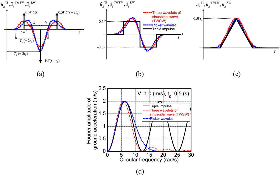
Figure 1. Triple impulse, three wavelets of sinusoidal waves (TWSW), and Ricker wavelet as simple forward-directivity input models: (A) ground acceleration, (B) ground velocity, (C) ground displacement, and (D) Fourier amplitude of ground acceleration.
The ground acceleration of the triple impulse
where
Equation 3 is used in Section 6 to adjust the input levels of these two inputs.
The time intervals between the first and second impulses and between the second and third impulses of the triple impulse shown in Equation 1 are the same; the triple impulse with the same two time intervals was called Input Sequence 2 (IS2) (Kojima and Takewaki, 2024). Although the two time intervals need to be the same for capturing the critical frequency of the forward-directivity input, the triple impulse (IS1), in which the second and third impulses act at zero-restoring force timing, is employed to drive an approximate solution of the critical triple-impulse responses using similar procedures in the previous works (Kojima and Takewaki, 2015b; Kojima and Hikita, 2020; Kojima and Takewaki, 2024). Therefore, the triple impulse, which has different time intervals, is defined as Equation 4:
where t1 (= 0), t2, and t3 are the acting timings of the first, second, and third impulses, respectively. The first and second time intervals ΔT1 (= t2 − t1) and ΔT2 (= t3 − t2) are defined as the time intervals between the first and second impulses and between the second and third impulses, respectively.
Since the characteristics of the forward-directivity input of near-fault ground motions are quite uncertain and the analysis of their effects on the structural response is also versatile and time-consuming, only the critical response producing the maximum effect is taken into account in this paper from the viewpoint of the reliability of the analysis.
A single-degree-of-freedom (SDOF) system with bilinear hysteresis and linear viscous damping of mass m, initial stiffness k, and damping coefficient c is considered, as shown in Figure 2. The relative displacement response, restoring force, and damping force are expressed by u, fR, and fD, respectively. dy, fy (= kdy), and α indicate the yield deformation (limit deformation of the elastic range), the yield force corresponding to the yield deformation, and the ratio of the post-yield stiffness (second stiffness) to the elastic stiffness of the bilinear hysteresis, respectively. Let
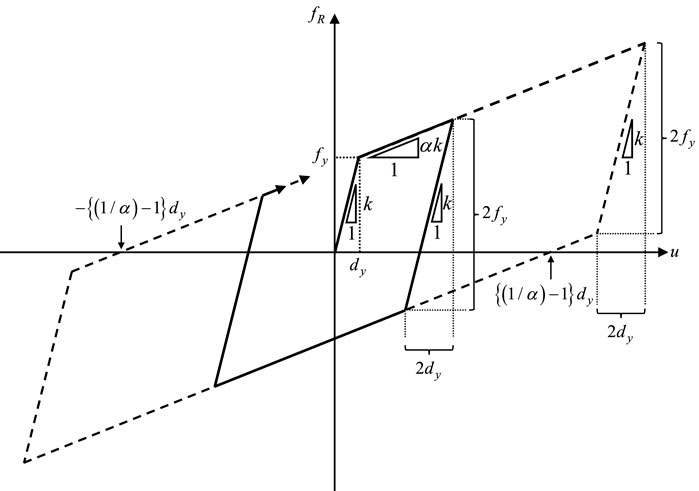
Figure 2. Bilinear hysteretic restoring-force characteristic.
In this section, the maximum elastic–plastic responses of the damped bilinear hysteretic SDOF system under the triple impulse in IS1 are compared with the critical triple impulse responses in IS2. The exact solutions of the elastic–plastic responses of the damped SDOF system to the triple impulse are difficult to derive. Therefore, the triple-impulse responses are calculated by the time-history response analysis (THRA) in this section. The critical triple impulse in IS2 is defined as the triple impulse with the critical time interval t0c, which maximizes the maximum displacement response, and the critical time interval t0c is captured by changing the time interval t0 from 0.1T1 to 1.0T1 in Equation 1 for the specific input velocity amplitude V/Vy.
Figures 3–5 show the comparison of the maximum displacement responses umax/dy normalized by the yield deformation under the triple impulse in IS1 and that under the critical triple impulse in IS2 for α = 0.01, 0.1, and 0.5 and h = 0, 0.01, 0.02, 0.05, 0.1, and 0.2 with respect to the normalized input velocity amplitude V/Vy. As can be seen from Figures 3, 5, when α = 0.01 and 0.5 and h = 0, 0.01, 0.02, and 0.05, the maximum triple-impulse responses in IS1 are larger than the critical responses in IS2 in the larger input level. On the other hand, as shown in Figures 3–5, in cases except those mentioned above, the maximum triple-impulse responses in IS1 can provide the critical response in IS2. The reasons for this are summarized below. For α = 0.01, in both the triple-impulse responses in IS1 and the critical responses under the triple impulse with IS2, the maximum response just after the second impulse, corresponding to umax2 shown in Section 5, determines the maximum displacement. In IS2 for h = 0, the third impulse acts in the loading process after the second impulse and makes the maximum response just after the second impulse smaller, as stated in Kojima and Takewaki (2015b) and Kojima and Takewaki (2024). A similar situation occurs for h = 0.01, 0.02, and 0.05 and the larger input level. In this situation, the critical timing of the second impulse in IS2 is longer than the zero-restoring force timing, and the maximum displacement in IS1 becomes slightly larger than that in the critical IS2. When α = 0.01 and h = 0.1 and 0.2, the third impulse acts in the unloading process after the maximum displacement just after the second impulse, and the critical timing of the second impulse is determined as the zero-restoring force timing in both IS1 and IS2. In this case, the maximum responses in IS1 and the critical IS2 are the same. When α = 0.1, both the maximum responses in IS1 and the critical IS2 are determined by the maximum displacement just after the second impulse, and the third impulse acts in the unloading process after the maximum displacement just after the second impulse, regardless of the damping ratio. Therefore, the critical timing of the second impulse is determined as the zero-restoring force timing in both IS1 and IS2, and the response in IS1 is equal to that in the critical IS2. When α = 0.5, the maximum response just after the third impulse, corresponding to umax3 shown in Section 5, becomes the maximum displacement to the triple impulse in all input levels for h = 0, as shown in Kojima and Takewaki (2024), and in the larger input level for h = 0.01, 0.02, 0.05. The critical timing in IS2 is determined to maximize the maximum displacement after the third impulse and is longer than the zero-restoring force timing. Therefore, the maximum displacement in IS1 becomes somewhat larger than that in IS2. On the other hand, when α = 0.5 and h = 0.1 and 0.2, the maximum displacement in both IS1 and the critical IS2 is determined by the maximum displacement just after the second impulse due to the large damping ratio. The critical timing of the second impulse in both input sequences is the zero-restoring force timing, and the maximum displacements are the same.
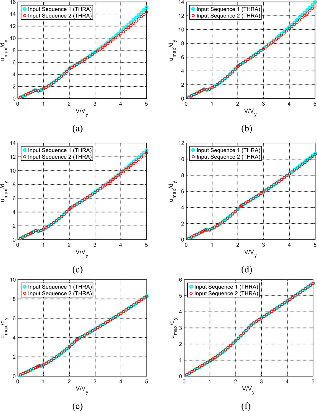
Figure 3. Comparison of the normalized maximum displacement response under triple impulse in IS1 with that under critical triple impulse in IS2 (α = 0.01): (A) h = 0, (B) h = 0.01, (C) h = 0.02, (D) h = 0.05, (E) h = 0.1, and (F) h = 0.2.
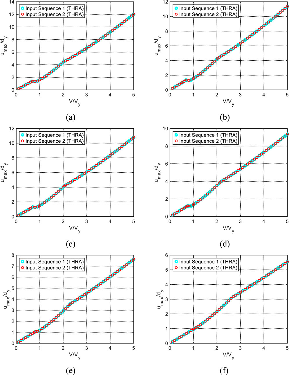
Figure 4. Comparison of the normalized maximum displacement response under triple impulse in IS1 with that under critical triple impulse in IS2 (α = 0.1): (A) h = 0, (B) h = 0.01, (C) h = 0.02, (D) h = 0.05, (E) h = 0.1, and (F) h = 0.2.
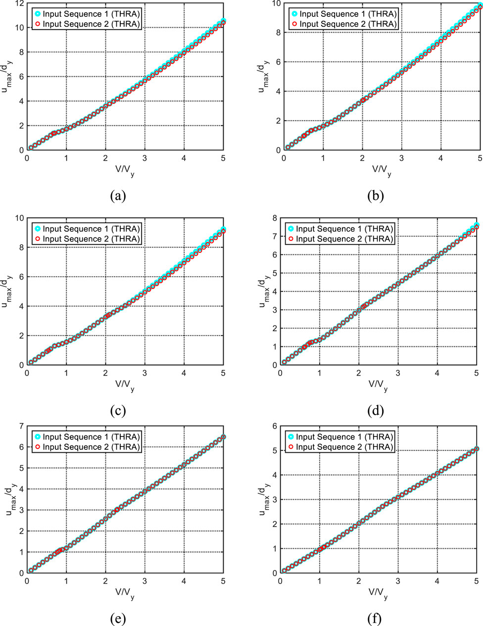
Figure 5. Comparison of the normalized maximum displacement response under triple impulse in IS1 with that under critical triple impulse in IS2 (α = 0.5): (A) h = 0, (B) h = 0.01, (C) h = 0.02, (D) h = 0.05, (E) h = 0.1, and (F) h = 0.2.
Figure 6 shows the maximum displacement response umax normalized by the yield deformation dy under the triple impulse in IS2 with respect to the time interval t0 shown in Equation 1 for a specific input velocity amplitude V/Vy for the SDOF system with α = 0.1 and 0.5 and h = 0.02 and 0.1. It can be seen that, as the input velocity amplitude becomes larger, the time interval attaining the maximum displacement response moves to a longer range depending on the post-yield stiffness ratio and the damping quantity.
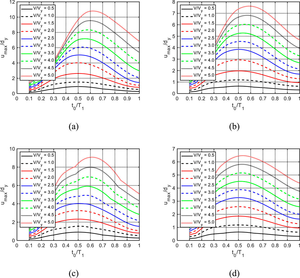
Figure 6. Normalized maximum displacement response umax/dy under triple impulse in IS2 with respect to time interval t0 for specific input velocity V/Vy: (A) α = 0.1, h = 0.02, (B) α = 0.1, h = 0.1, (C) α = 0.5, h = 0.02, and (D) α = 0.5, h = 0.1.
In the previous papers (Kojima and Takewaki, 2015b; Kojima and Takewaki, 2024; Kojima and Hikita, 2020), it was assumed that the elastic–plastic response under the triple impulse in IS1, whose second and third impulses act at zero-restoring force timings, provides the upper bound of that under the critical triple impulse (IS2) with the same time intervals, and the exact or approximate expressions of the elastic–plastic responses under the triple impulse were derived. In Section 5, approximate expressions are obtained for the triple-impulse responses in IS1 of the SDOF systems with bilinear hysteresis and viscous damping by using an approximation of the damping force–displacement relationship and an energy balance law based on the previous works (Kojima et al., 2018; Akehashi et al., 2018a; Kojima and Hikita, 2020). In Section 4, the response of the damped SDOF bilinear system under the triple impulse with IS1 is the same or slightly larger than the critical response under the triple impulse in IS2. Therefore, the approximate expression of the triple-impulse response in IS1 is useful for evaluating the upper bound of the critical elastic–plastic response under the triple impulse in IS2 (two time intervals are the same). Since it seems difficult to obtain the critical timing for IS2 in a simple manner, the critical triple-impulse response in IS2 is difficult to derive in a similar manner, as shown for IS1. It is hoped to obtain an approximate expression for the free vibration of the damped elastic–plastic system and approximately derive the critical triple impulse responses in IS2.
The triple-impulse responses in IS1 are summarized in Figure 7. The triple-impulse response in IS1 of an SDOF system with viscous damping and bilinear hysteresis can be classified into seven cases, as stated below and summarized in Table 1, depending on whether the system yields after each impulse, as shown in the previous work (Kojima and Takewaki, 2024).
CASE 1: the elastic response even after the third impulse.
CASE 2: the system yields after the third impulse.
CASE 3–1: the system yields after the second impulse, and the third impulse acts in the unloading process (initial stiffness range).
CASE 3–2: the system yields after the second impulse, and the third impulse acts in the post-yield stiffness range (second stiffness range).
CASE 4–1: the system yields after the first impulse, and the second and third impulses act in the unloading process (initial stiffness range).
CASE 4–2: the system yields after the first impulse, the second impulse acts in the initial stiffness range, and the third impulse acts in the second stiffness range.
CASE 4–3: the system yields after the first impulse, and both the second and third impulses act in the second stiffness range.
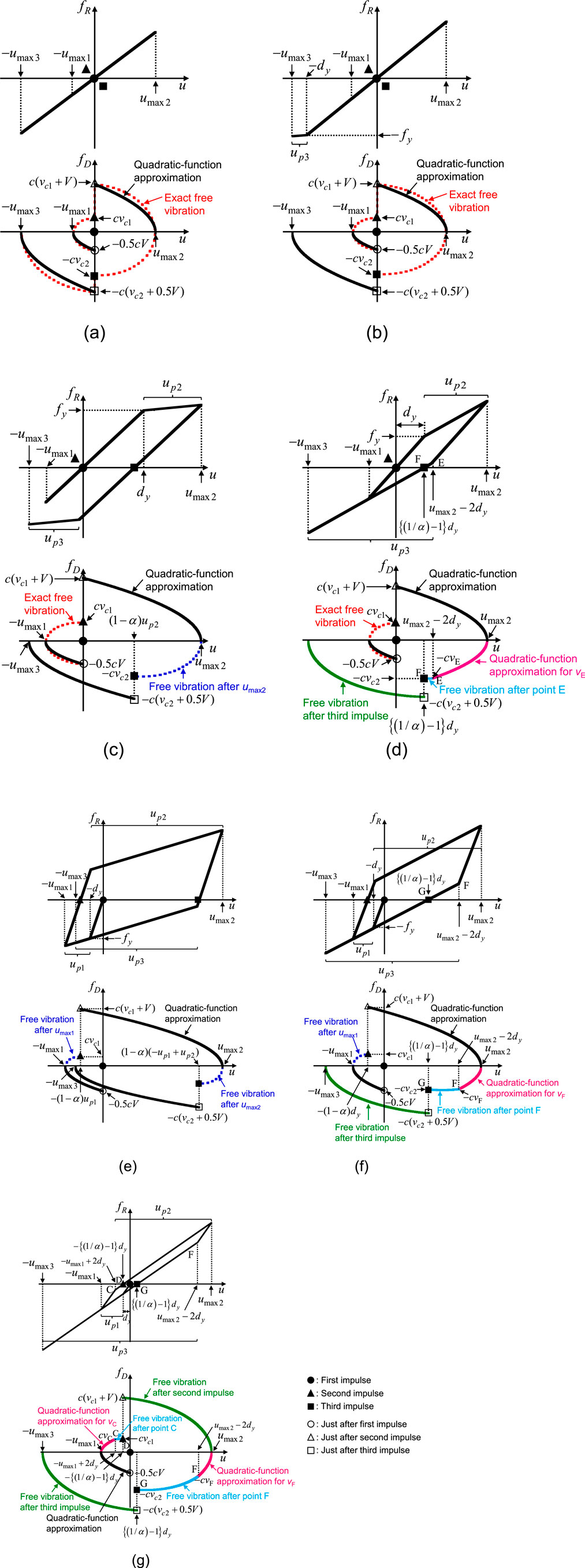
Figure 7. Schematic diagram of restoring force–displacement relationship and approximate damping force–displacement relationship of triple-impulse responses in IS1: (A) CASE 1, (B) CASE 2, (C) CASE 3–1, (D) CASE 3–2, (E) CASE 4–1, (F) CASE 4–2, and (G) CASE 4–3 (●: first impulse timing, ▲: second impulse timing, and ■: third impulse timing) .
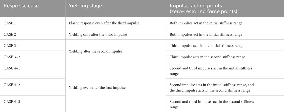
Table 1. Classification of the elastic–plastic response under triple impulse in IS1.
Figure 7 shows the schematic diagram of the restoring force fR–displacement u relationship and the approximate damping force fD–displacement u relationship for each response case. It should be noted that each case is determined by the second stiffness ratio α and the input level. It is shown in Section 5.3 which cases occur for several α as the input level increases. Let umax1, umax2, and umax3 denote the maximum displacement (absolute values) just after the first, second, and third impulses, respectively. Similarly, the plastic deformation just after each impulse is denoted by up1, up2, and up3.
Approximate expressions are derived in this section for the triple-impulse responses in IS1 of the SDOF systems with bilinear hysteresis and viscous damping. There are two procedures for deriving the maximum displacement response and plastic deformation after each impulse, depending on the state of the impulse-acting point. For the response after the first, second, or third impulses acting in the initial stiffness range, the damping force–displacement relationship is approximated, and the work done by the damping force between the impulse acting point and the maximum displacement point is formulated. Then, the maximum displacement response and plastic deformation just after each impulse are obtained by using the energy balance law (Kojima et al., 2018; Akehashi et al., 2018a; Kojima and Hikita, 2020). In this procedure, the velocity at the impulse acting point (the zero-restoring force timing) after the elastic–plastic response can be obtained by the free vibration response after the maximum response and that after the elastic response can be formulated by the exact linear free vibration solution after the previous impulses.
On the other hand, the response after the second or third impulse acting in the post-yield stiffness range is obtained by the following procedure proposed by Akehashi et al. (2018a). The damping force–displacement relationship in the unloading process after the maximum displacement is approximated by a quadratic function, and then, the work done by the damping force between the maximum displacement after the previous impulse and the re-yielding point is formulated. The approximate expression of the velocity at the zero-restoring force timing in the post-yield stiffness range can be obtained by free vibration, which can be obtained by using the initial condition at the re-yielding point. The maximum displacement can then be formulated approximately by using the free vibration derived by using the initial condition at the impulse-acting point (the zero-restoring force timing).
The diagrams of the two procedures are shown in Figure 8.
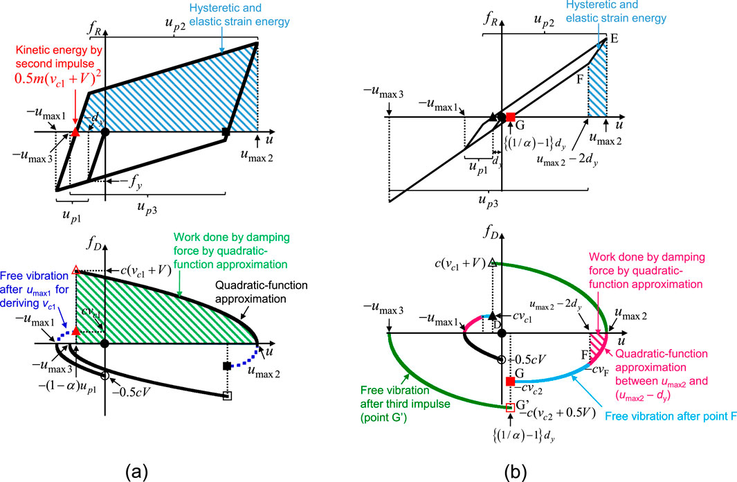
Figure 8. Schematic diagram of two deriving procedures for triple impulse (IS1). (A) Derivation of maximum displacement after second impulse acting at zero-restoring force point in the elastic stiffness range in CASE 4–1. (B) Derivation of maximum displacement after third impulse at the zero-restoring force point in the post-yield stiffness range in CASE 4–3 (●: first impulse timing, ▲: second impulse timing and ■: third impulse timing).
The approximate expressions of the maximum displacement responses under the triple impulse in IS1 are summarized below. In the following equations,
The triple-impulse response in CASE 1, as shown in Figure 7A, remains in the elastic range even after the third impulse. Kojima and Hikita (2020) obtained the approximate expressions of the triple-impulse responses in CASE 1, which are summarized as follows:
In the derivation of Equations 6, 7, the velocities
The velocities
The exact solutions of the triple-impulse responses in IS1 of the elastic SDOF system with viscous damping can be obtained from the free vibration responses. The time intervals of the triple impulse (IS1) are
In CASE 2, a plastic deformation appears only after the third impulse. Figure 7B shows the schematic diagram of the triple-impulse response in CASE 2. The boundary input level V/Vy between CASEs 1 and 2 can be obtained by Equation 7 and umax3 = dy and is expressed by Equation 13 (Kojima and Hikita, 2020):
However, if the damping ratio h is larger than 0.151409, it is noted that the maximum displacement response umax2 just after the second impulse becomes larger than the maximum displacement response umax3 after the third impulse.
In CASE 2, umax1 and umax2 are in the elastic range and are calculated using Equations 5, 6. The plastic deformation up3 and the maximum displacement umax3 are obtained as follows:
where vc2/Vy in Equations 14, 15 can be obtained by Equation 9.
In CASEs 3–1 and 3–2, the displacement response is beyond the yield deformation after the second impulse. CASE 3–1, as shown in Figures 7C, is the case where the third impulse acts in the unloading range (initial stiffness range), and CASE 3–2, as shown in Figures 7D, is the case where the third impulse acts in the second stiffness range. The boundary input level V/Vy between CASEs 2 and 3–1 can be obtained by Equation 6 and umax2 = dy and is expressed by Equation 16 (Kojima and Hikita, 2020):
In CASEs 3–1 and 3–2, umax1 is in the elastic range and is calculated using Equation 5. The plastic deformations up2 and up3 and the maximum displacements umax2 and umax3 in CASE 3–1 are summarized as Equations 17–20:
where vc1/Vy in Equations 17, 18 can be obtained by Equation 8 and vc2/Vy in Equation 19, which is the velocity at the zero-restoring force timing in the free vibration after the maximum displacement point umax2, can be calculated using Equation 21 (Akehashi et al., 2018a):
The schematic diagram of CASE 3–2 is shown in Figure 7D. When
In CASE 3–2, umax1, up2, and umax2 are calculated using Equation 5 in CASE 1 and Equations 17, 18 in CASE 3–1, respectively. The maximum displacement umax3 in CASE 3–2 is summarized as Equation 23:
where
where
where vE denotes the absolute value of the velocity at point E shown in Figure 7D (Equations 24–28).
In CASEs 4–1, 4–2, and 4–3, the elastic–plastic response appears even after the first impulse. CASE 4–1, as shown in Figures 7E, is the case where both the second and third impulses act in the unloading range, and CASE 4–2, as shown in Figures 7F, is the case where the third impulse only acts in the post-yield stiffness range. The boundary input level V/Vy between CASEs 3–1 and 4–1 or CASEs 3–2 and 4–2 can be obtained by Equation 5 and umax1 = dy and is expressed by Equation 29 (Kojima and Hikita, 2020):
Depending on the values of the post-yield stiffness ratio α and the damping ratio h, the order of the cases differs as V/Vy increases.
The plastic deformations up1, up2, and up3 and the maximum displacements umax1, umax2, and umax3 in CASE 4–1 can be summarized as Equations 30–35:
where vc1/Vy and vc2/Vy in Equations 32, 34, which are the velocities at the zero-restoring force timing in the free vibration after the maximum displacement points umax1 and umax2, can be calculated using Equations 36, 37 (Akehashi et al., 2018a):
The schematic diagram of the triple-impulse response in CASE 4–2 is shown in Figure 7F. When
In CASE 4–2, up1, umax1, up2, and umax2 are calculated using Equations 30–33 in CASE 4–1, respectively. The maximum displacement umax3 after the third impulse in CASE 4–2 can be derived by using the same procedure shown in Akehashi et al. (2018a) and is summarized as follows:
where vc2 denotes the absolute value of the velocity at the zero-restoring force timing (point G in Figure 7F) and can be expressed as
where
where vF denotes the absolute value of the velocity at point F, as shown in Figure 7F.
The schematic diagram of the triple-impulse response in CASE 4–3 is shown in Figure 7G. When
In CASE 4–3, up1 and umax1 are calculated using Equations 30, 31 in CASE 4–1. The maximum displacement umax2 in CASE 4–3 is summarized as follows:
where vc1 denotes the velocity at the zero-restoring force timing (point D in Figure 7G) and can be expressed as
where
where vC denotes the velocity at point C, as shown in Figure 7G (Equations 46–51):
umax3 in CASE 4–3 can be obtained by substituting umax2/dy obtained from Equation 46 into Equations 39–44 in CASE 4–2.
The maximum deformation of the damped bilinear hysteretic SDOF system under the triple impulse in IS1 is evaluated using the approximate expressions obtained in Section 5.2. Figures 9–11 show the normalized maximum displacement response umax/dy to the triple impulse in IS1 with respect to the input level V/Vy evaluated for the post-yield stiffness ratio α = 0.01, 0.1, and 0.5 and the damping ratio h = 0, 0.01, 0.02, 0.05, and 0.1 using the approximate expressions. Figures 9–11 show that umax = max (umax1, umax2, umax3). It can be observed from Equations 6, 7 that when the damping ratio h ≥ 0.151409, umax2 is larger than umax3 in the elastic response (CASE 1). In this case, when the input amplitude becomes larger, umax2 exceeds the yield deformation before the system yields after the third impulse. Therefore, this case is different from the case assumed in Section 5.1. The system with the damping ratio h ≥ 0.151409 is out of range of application of the approximate expression derived in Section 5.2.
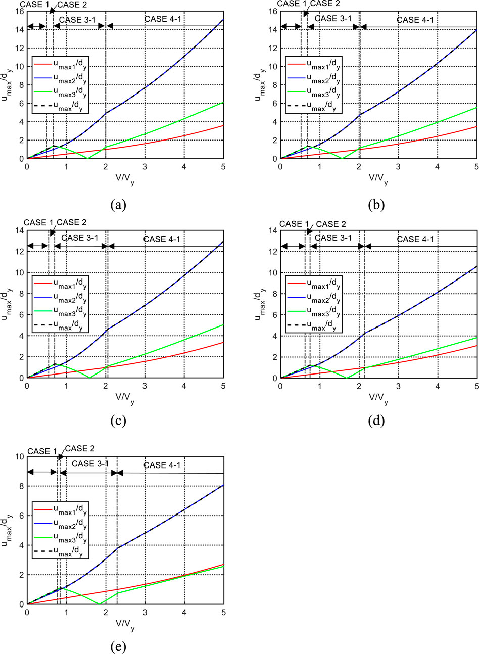
Figure 9. Normalized maximum displacement response umax/dy under triple impulse in IS1 with respect to input level V/Vy evaluated by approximate expression (α = 0.01): (A) h = 0 from Kojima and Takewaki (2024), (B) h = 0.01, (C) h = 0.02, (D) h = 0.05, and (E) h = 0.1.

Figure 10. Normalized maximum displacement response under triple impulse in IS1 with respect to input level V/Vy evaluated by approximate expression (α = 0.1): (A) h = 0 from Kojima and Takewaki (2024), (B) h = 0.01, (C) h = 0.02, (D) h = 0.05, and (E) h = 0.1.
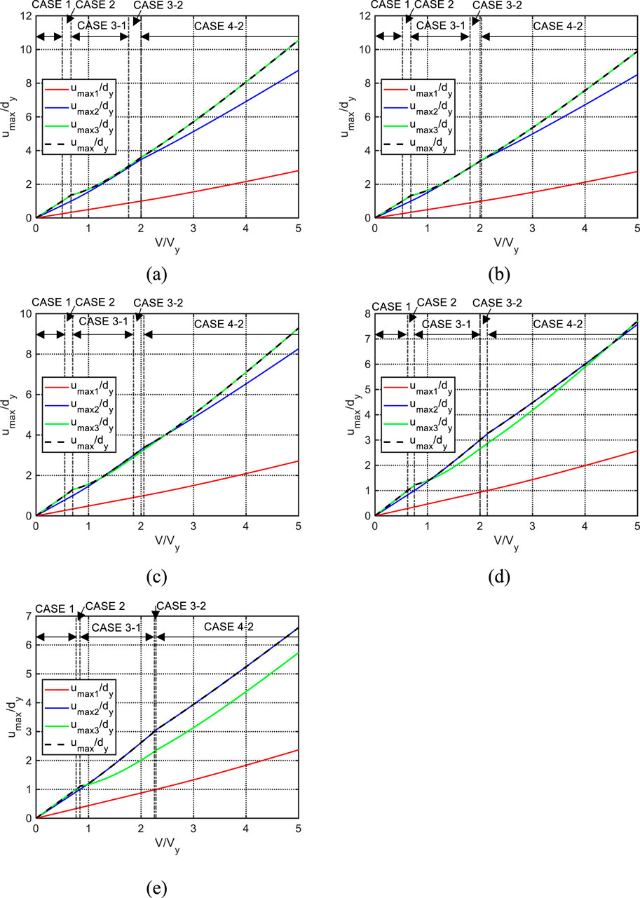
Figure 11. Normalized maximum displacement response under triple impulse in IS1 with respect to input level V/Vy evaluated by approximate expression (α = 0.5): (A) h = 0 from Kojima and Takewaki (2024), (B) h = 0.01, (C) h = 0.02, (D) h = 0.05, and (E) h = 0.1.
Figures 9, 10 show that, when the post-yield stiffness ratio α = 0.01 and 0.1, umax2 is the largest in the larger input level (about 1 ≤ V/Vy) for any damping ratio. On the other hand, Figure 11 shows that when α = 0.5, there is a range of the input level where umax3 is the largest in CASEs 3–1, 3–2, and 4–2 for the damping ratio h = 0, 0.01, 0.02, and 0.05. However, when α = 0.5 and h = 0.1, umax2 is the largest in the larger input level (about 1 ≤ V/Vy). Figures 9–11 show that CASE 4–1 appears after CASE 3–1 for α = 0.01 and 0.1 as V/Vy becomes larger, and the cases for α = 0.5 change in the order of CASEs 1, 2, 3–1, 3–2, and 4–2 as V/Vy increases.
The approximate triple-impulse responses in IS1 derived in Section 5.2 are compared with those calculated by the time-history response analysis (THRA) to investigate their accuracy. Figures 12, 13 show the comparison of the normalized maximum displacement response of the damped bilinear hysteretic SDOF system under the triple impulse in IS1 calculated by the approximated expressions and that obtained by THRA. In Figures 12, 13, umax = max (umax1, umax2, umax3). It can be observed from Figures 12, 13 that the approximate expressions can predict the triple-impulse response in IS1 with reasonable accuracy. It may be meaningful to consider the limit case of α = 1.0 (elastic) and h = 0 (undamped). Since the energy is stored successively when each impulse is given, it is clear that the maximum deformation occurs after the third impulse and the critical timing is the moment of peak velocity. In some cases for the damped bilinear hysteretic system with a smaller α and/or a larger h, the maximum velocity occurs at the timing just after the second impulse because of the energy dissipation by the plastic deformation and the viscous damping and because the given initial velocity by the second impulse is twice that by the third impulse.

Figure 12. Comparison of normalized maximum displacement under triple impulse in IS1 by approximate expressions and that by time-history response analysis (α = 0.1): (A) h = 0.02, (B) h = 0.02 (magnified), (C) h = 0.1, and (D) h = 0.1 (magnified).

Figure 13. Comparison of normalized maximum displacement under triple impulse in IS1 by approximate expressions and that by time-history response analysis (α = 0.5): (A) h = 0.02, (B) h = 0.02 (magnified), (C) h = 0.1, and (D) h = 0.1 (magnified).
To investigate the validity of modeling the forward-directivity input by the triple impulse, the elastic–plastic responses under the triple impulse in IS1 and the critical triple impulse in IS2 are compared with the elastic–plastic response to TWSW and the Ricker wavelet, which have been employed to simulate the ground acceleration of the forward-directivity pulse (Sasani and Bertero, 2000; Kalkan and Kunnath, 2006; Minami and Hayashi, 2013; Khaloo et al., 2015; Okazawa et al., 2018).
To compare the elastic–plastic responses under these inputs, the TWSW and the Ricker wavelet equivalent to the triple impulse in IS2 in Equation 1 are set according to the following procedure. As mentioned in Section 2, the pulse period Tp of the TWSW in Equation 2 is twice of the time interval t0 of the triple impulse in IS2 in Equation 1, and the ground acceleration amplitude Ap in Equation 2 can be determined from the velocity amplitude V of the triple impulse and
The ground acceleration of the forward-directivity pulse modeled by the Ricker wavelet is expressed by (Minami and Hayashi, 2013; Okazawa et al., 2018)
where Tp = 2t0 and ApRW is the maximum ground acceleration of the Ricker wavelet. The Fourier amplitude of the Ricker wavelet in Equation 52 attains the maximum at ω = ωp, and its maximum Fourier amplitude is
Figure 1D shows the Fourier amplitudes of the triple impulse, the TWSW, and the Ricker wavelet for V = 1.0 m/s and t0 = 0.5 s, whose ground acceleration amplitudes Ap and ApRW are adjusted so that their maximum Fourier amplitudes are the same.
Figure 14 shows the comparison of the ductility (the maximum displacement response) to the triple impulse in IS1, the critical triple impulse in IS2, the TWSW, and the Ricker wavelet. The time interval t0c, which maximizes umax under the triple impulse in IS2, is adopted as t0 (= Tp/2) for the TWSW and the Ricker wavelet. The time-history response analysis is used to calculate the responses under the triple impulse (IS1 and IS2), the TWSW, and the Ricker wavelet in this section. The response to the triple impulse (IS1) is also obtained by the approximate expressions (AE) derived in Section 5.2. When α = 0.01 and h = 0.01, the triple-impulse response in IS1 by AE and THRA can evaluate the response under the Ricker wavelet with reasonable accuracy, and the response to the critical triple impulse in IS2 corresponds well to the response to the TWSW. When α = 0.1 and 0.5 and h = 0.01, the responses under the triple impulse in IS1 (THRA and AE), the critical triple impulse in IS2, TWSW, and the Ricker wavelet are almost the same. On the other hand, when h = 0.1, the response under the Ricker wavelet is slightly larger than both the triple-impulse responses (IS1 and critical IS2). This is because, while the response under the Ricker wavelet is a forced vibration, the triple-impulse response is a series of free vibrations. Although the response under the Ricker wavelet is slightly larger than that under the triple impulse (IS1) and the critical triple impulse (IS2) for the system with h = 0.1, the responses of the system with bilinear hysteresis and viscous damping to the TWSW and the Ricker wavelet can be estimated by the approximate expressions of the triple-impulse response (IS1).
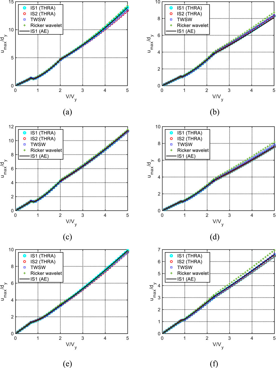
Figure 14. Comparison of normalized maximum deformation umax/dy under triple impulse with IS1 and critical triple impulse with IS2, TWSW, and Ricker wavelet: (A) α = 0.01 and h = 0.01; (B) α = 0.01 and h = 0.1; (C) α = 0.1 and h = 0.01; (D) α = 0.1 and h = 0.1; (E) α = 0.5 and h = 0.01; and (F) α = 0.5 and h = 0.1.
Two types of sequences of a triple impulse, as one of the mathematical models of forward-directivity inputs, were proposed. One is the triple impulse, in which the timings of the second and third impulses are the zero-restoring force timings. This is called Input Sequence 1 (IS1). The other is Input Sequence 2 (IS2) with the same time interval. Then, the elastic–plastic responses of an SDOF system with bilinear hysteresis and linear viscous damping under the triple impulse (IS1) and the critical triple impulse (IS2) were calculated and compared. The critical triple impulse (IS2) was defined as the triple impulse with the critical time interval that maximizes the maximum displacement response when the time interval with the same value was changed. Furthermore, approximate expressions were derived for the elastic–plastic responses of the SDOF system with bilinear hysteresis and viscous damping under the triple impulse (IS1). To validate the appropriateness of the triple impulse as the mathematical model of the directivity pulse, the responses under the triple impulse (IS1) and the critical triple impulse (IS2) were compared with those under the equivalent three wavelets of sinusoidal waves (TWSW) and the Ricker wavelet. The conclusions are summarized as follows:
(1) The elastic–plastic responses of the damped bilinear hysteretic SDOF system under the triple impulse (IS1) were calculated for various normalized input velocity levels by the time-history response analysis and compared with those under the critical triple impulse (IS2) calculated by the time-history response analysis for the post-yield stiffness ratio α = 0.01, 0.1, and 0.5 and the damping ratio h = 0, 0.01, 0.02, 0.05, 0.1, and 0.2. The critical time interval of the triple impulse (IS2) was calculated by changing the same time interval and captured as the time interval that maximizes the maximum displacement response to the triple impulse (IS2). When the second stiffness ratio α is 0.01 and 0.5 and the damping ratio h is 0, 0.01, 0.02, and 0.05, the elastic–plastic responses under the triple impulse (IS1) were larger than those under the critical triple impulse (IS2) in the larger input velocity level. On the other hand, for the systems except those mentioned above, the elastic–plastic responses under the triple impulse (IS1) and the critical triple impulse (IS2) were the same even in the larger input level.
(2) Approximate expressions were derived for the elastic–plastic responses of the damped bilinear hysteretic SDOF system under the triple impulse (IS1) using the quadratic-function approximation of the damping force–displacement relationship and energy balance equations. The responses to the triple impulse (IS1) were classified into seven cases depending on the timing of the system yielding and whether the second and third impulses act in the unloading process (initial stiffness range) or post-yield stiffness range. When the impulses act at the zero-restoring force point in the initial stiffness range, the work done by the damping force can be formulated from the quadratic-function approximation of the damping force–displacement relationship, and the maximum displacement just after each impulse can be obtained from the energy balance equation between the impulse acting point and the maximum displacement point. On the other hand, when the second or third impulse acts at the zero-restoring force point in the post-yield stiffness range, the work done by the damping force between the maximum displacement after the previous impulse and the re-yielding point can be formulated using the approximated damping force–displacement relationship by a quadratic function, and the velocity at the re-yielding point can be derived from the energy balance equation. Then, the velocity at the zero-restoring force point and the maximum displacement after each impulse can be obtained from the free vibration in the post-yield stiffness range.
(3) The accuracy of the approximate expressions was investigated by comparing the response under the triple impulse (IS1) obtained by the approximate expressions with that by the time-history response analysis. As for the conclusion (1), it was found that the elastic–plastic response under the triple impulse (IS1) was slightly larger than or the same as that under the critical triple impulse (IS2). Therefore, the elastic–plastic responses of the damped bilinear hysteretic system under both the triple impulse (IS1) and the critical triple impulse (IS2) can be estimated in a simple manner by the approximate expressions for the triple impulse (IS1).
(4) To validate the appropriateness of the triple impulse as a simple mathematical ground motion model of the forward directivity pulse, the elastic–plastic responses to the triple impulse (IS1) and the critical triple impulse (IS2) were compared with those under TWSW and the Ricker wavelet, which were commonly used as ground motion models of the forward-directivity pulse. The pulse periods of the TWSW and the Ricker wavelet were twice the critical time interval of the triple impulse (IS2), and their acceleration amplitudes were scaled so that the maximum Fourier amplitudes of the triple impulse (IS2), the TWSW, and the Ricker wavelet were the same. Although the responses under the equivalent Ricker wavelet were slightly larger than those under the triple impulse (IS1) and the critical triple impulse (IS2) for the damping ratio h = 0.1, the elastic–plastic responses to the equivalent TWSW and the Ricker wavelet can be estimated by that to the triple impulse (IS1).
The raw data supporting the conclusions of this article will be made available by the authors, without undue reservation.
KK: writing–original draft, writing–review and editing, conceptualization, data curation, formal analysis, funding acquisition, investigation, methodology, project administration, resources, software, supervision, validation, and visualization. IT: conceptualization, methodology, project administration, supervision, writing–original draft, and writing–review and editing.
The author(s) declare that financial support was received for the research, authorship, and/or publication of this article. This research is partially supported by KAKENHI of the Japan Society for the Promotion of Science (No. 23K13439).
The authors declare that the research was conducted in the absence of any commercial or financial relationships that could be construed as a potential conflict of interest.
The author(s) declared that they were an editorial board member of Frontiers, at the time of submission. This had no impact on the peer review process and the final decision.
The author(s) declare that no Generative AI was used in the creation of this manuscript.
All claims expressed in this article are solely those of the authors and do not necessarily represent those of their affiliated organizations, or those of the publisher, the editors and the reviewers. Any product that may be evaluated in this article, or claim that may be made by its manufacturer, is not guaranteed or endorsed by the publisher.
Akehashi, H., Kojima, K., Farsangi, E. N., and Takewaki, I. (2018b). Critical response evaluation of damped bilinear hysteretic SDOF model under long duration ground motion simulated by multi impulse motion. Int. J. Earthq. Impact Eng. 2 (4), 298–321. doi:10.1504/IJEIE.2018.099361
Akehashi, H., Kojima, K., and Takewaki, I. (2018a). Critical response of single-degree-of-freedom damped bilinear hysteretic system under double impulse as substitute for near-fault ground motion. Front. Built Environ. 4, 5. doi:10.3389/fbuil.2018.00005
Akehashi, H., and Takewaki, I. (2019). Optimal viscous damper placement for elastic-plastic MDOF structures under critical double impulse. Front. Built Environ. 5, 20. doi:10.3389/fbuil.2019.00020
Akehashi, H., and Takewaki, I. (2021). Pseudo-double impulse for simulating critical response of elastic-plastic MDOF model under near-fault earthquake ground motion. Soil Dyn. Earthq. Eng. 150, 106887. doi:10.1016/j.soildyn.2021.106887
Akehashi, H., and Takewaki, I. (2022a). Closed-form critical response of undamped bilinear hysteretic MDOF system under pseudo-double impulse for estimating resonant response under one-cycle sine wave. Soil Dyn. Earthq. Eng. 157, 107254. doi:10.1016/j.soildyn.2022.107254
Akehashi, H., and Takewaki, I. (2022b). Closed-form critical response of elastic-plastic shear building with viscous damper under pseudo-double impulse for simulating resonant response under near-fault fling-step motion. Front. Built Environ. 8, 964867. doi:10.3389/fbuil.2022.964867
Alavi, B., and Krawinkler, H. (2001). Effects of near-fault ground motions on frame structures, John A Blume Earthquake Engineering Center Technical Report 138, Stanford Digital Repository. Available at: http://purl.stanford.edu/cx534fy3768.
Alavi, B., and Krawinkler, H. (2004). Behavior of moment-resisting frame structures subjected to near-fault ground motions. Earthq. Eng. Struct. Dyn. 33 (6), 687–706. doi:10.1002/eqe.369
Bertero, V. V., Mahin, S. A., and Herrera, R. A. (1978). Aseismic design implications of near-fault San Fernando earthquake records. Earthq. Eng. Struct. Dyn. 6 (1), 31–42. doi:10.1002/eqe.4290060105
Fujii, K. (2024a). Critical pseudo-double impulse analysis evaluating seismic energy input to reinforced concrete buildings with steel damper columns. Front. Built Environ. 10, 1369589. doi:10.3389/fbuil.2024.1369589
Fujii, K. (2024b). Seismic capacity evaluation of reinforced concrete moment-resisting frames with steel damper columns using incremental critical pseudo-multi impulse analysis. Front. Built Environ. 10, 1431000. doi:10.3389/fbuil.2024.1431000
Kalkan, E., and Kunnath, S. K. (2006). Effects of fling step and forward directivity on seismic response of buildings. Earthq. Spectra 22 (2), 367–390. doi:10.1193/1.2192560
Khaloo, A. R., Khosravi, H., and Hamidi Jamnani, H. (2015). Nonlinear interstory drift contours for idealized forward directivity pulses using “Modified Fish-Bone” models. Adv. Struct. Eng. 18 (5), 603–627. doi:10.1260/1369-4332.18.5.603
Kojima, K., and Hikita, R. (2020). Critical response of single-degree-of-freedom elastic-perfectly plastic system with viscous damping to forward-directivity input modeled by triple impulse. J. Struct. Eng. 66B, 451–461. (in Japanese).
Kojima, K., Saotome, Y., and Takewaki, I. (2018). Critical earthquake response of a SDOF elastic-perfectly plastic model with viscous damping under double impulse as a substitute for near-fault ground motion. Jpn. Archit. Rev. 1 (2), 207–220. doi:10.1002/2475-8876.10019
Kojima, K., and Takewaki, I. (2015a). Critical earthquake response of elastic-plastic structures under near-fault ground motions (Part 1: fling-step input). Front. Built Environ. 1, 12. doi:10.3389/fbuil.2015.00012
Kojima, K., and Takewaki, I. (2015b). Critical earthquake response of elastic-plastic structures under near-fault ground motions (Part 2: forward-directivity input). Front. Built Environ. 1, 13. doi:10.3389/fbuil.2015.00013
Kojima, K., and Takewaki, I. (2015c). Critical input and response of elastic-plastic structures under long-duration earthquake ground motions. Front. Built Environ. 1, 15. doi:10.3389/fbuil.2015.00015
Kojima, K., and Takewaki, I. (2016). Closed-form critical earthquake response of elastic-plastic structures with bilinear hysteresis under near-fault ground motions. J. Struct. Constr. Eng. (Transactions of AIJ) 726, 1209–1219. (in Japanese). doi:10.3130/aijs.81.1209
Kojima, K., and Takewaki, I. (2017). Critical steady-state response of single-degree-of-freedom bilinear hysteretic system under multi impulse as substitute of long-duration ground motion. Front. Built Environ. 3, 41. doi:10.3389/fbuil.2017.00041
Kojima, K., and Takewaki, I. (2024). “Earthquake response of SDOF bilinear hysteretic system under forward-directivity input modeled by triple impulse,” in Proc. of the 26th Australasian Conference on the Mechanics of Structures and Materials (ACMSM 2023). Lecture notes in civil engineering. Editors N. Chouw, and C. Zhang (Singapore: Springer), 513, 629–639. doi:10.1007/978-981-97-3397-2_54
Makris, N., and Black, C. J. (2004). Dimensional analysis of rigid-plastic and elastoplastic structures under pulse-type excitations. J. Eng. Mech. ASCE 130 (9), 1006–1018. doi:10.1061/(ASCE)0733-9399(2004)130:9(1006)
Mavroeidis, G. P., Dong, G., and Papageorgiou, A. S. (2004). Near-fault ground motions, and the response of elastic and inelastic single-degree-of-freedom (SDOF) systems. Earthq. Eng. Struct. Dyn. 33, 1023–1049. doi:10.1002/eqe.391
Mavroeidis, G. P., and Papageorgiou, A. S. (2003). A mathematical representation of near-fault ground motions. Bull. Seismol. Soc. Am. 93 (3), 1099–1131. doi:10.1785/0120020100
Minami, H., and Hayashi, Y. (2013). Response characteristics evaluation of elastic shear beam for pulse waves. J. Struct. Constr. Eng. (Transactions of AIJ) 685, 453–460. (in Japanese). doi:10.3130/aijs.78.453
Okazawa, R., Sugino, M., and Hayashi, Y. (2018). Modeling of super high-rise buildings and response properties against Ricker wavelet -Damage prediction for super high-rise buildings in Osaka against pulse-like ground motions: Part 1-. J. Struct. Constr. Eng. (Transactions of AIJ) 745, 421–430. (in Japanese). doi:10.3130/aijs.83.421
Sakai, Y., Minami, T., and Kabeyasawa, T. (2000). Simplification of strong motion considering inelastic responses of structures. Earthq. Eng. Struct. Dyn. 29, 823–846.
Sasani, M., and Bertero, V. V. (2000). “Importance of severe pulse-type ground motions in performance-based engineering: historical and critical review,” in Proc. of the Twelfth World Conference on Earthquake Engineering (Auckland, New Zealand).
Takewaki, I., and Kojima, K. (2021). An impulse and earthquake energy balance approach in nonlinear structural dynamics. Boca Raton, FL: CRC Press.
Takewaki, I., and Tsujimoto, H. (2011). Scaling of design earthquake ground motions for tall buildings based on drift and input energy demands. Earthq. Struct. 2, 171–187. doi:10.12989/eas.2011.2.2.171
Tamura, G., Kojima, K., and Takewaki, I. (2019). Critical response of elastic-plastic SDOF systems with nonlinear viscous damping under simulated earthquake ground motions. Heliyon 5, e01221. doi:10.1016/j.heliyon.2019.e01221
Keywords: critical earthquake response, triple impulse, forward-directivity input, single-degree-of-freedom system, bilinear hysteresis, viscous damping
Citation: Kojima K and Takewaki I (2025) Critical response of a single-degree-of-freedom system with bilinear hysteresis and viscous damping under triple impulse. Front. Built Environ. 11:1539299. doi: 10.3389/fbuil.2025.1539299
Received: 04 December 2024; Accepted: 20 January 2025;
Published: 06 March 2025.
Edited by:
Saber Moradi, Western University, CanadaReviewed by:
Chia-Ming Chang, National Taiwan University, TaiwanCopyright © 2025 Kojima and Takewaki. This is an open-access article distributed under the terms of the Creative Commons Attribution License (CC BY). The use, distribution or reproduction in other forums is permitted, provided the original author(s) and the copyright owner(s) are credited and that the original publication in this journal is cited, in accordance with accepted academic practice. No use, distribution or reproduction is permitted which does not comply with these terms.
*Correspondence: Kotaro Kojima, a29qaW1hNjFAa2l0LmFjLmpw
Disclaimer: All claims expressed in this article are solely those of the authors and do not necessarily represent those of their affiliated organizations, or those of the publisher, the editors and the reviewers. Any product that may be evaluated in this article or claim that may be made by its manufacturer is not guaranteed or endorsed by the publisher.
Research integrity at Frontiers
Learn more about the work of our research integrity team to safeguard the quality of each article we publish.