 Boxiong Wang
 Kohju Ikago
 Shotaro Kezuka
95% of researchers rate our articles as excellent or good
Learn more about the work of our research integrity team to safeguard the quality of each article we publish.
Find out more
ORIGINAL RESEARCH article
Front. Built Environ. , 30 May 2024
Sec. Earthquake Engineering
Volume 10 - 2024 | https://doi.org/10.3389/fbuil.2024.1411170
The resistive force of linear viscous damping (LVD), which is commonly used as a damping model for structures, decreases proportionally with the frequency. Another linear damping model known as the rate-independent linear damping (RILD) model is used as a linear mathematical model for representing the damping characteristics of structures and materials that have a low frequency dependency. Because the resistive force of RILD is proportional to the displacement amplitude instead of the velocity, it is expected to directly and effectively control the seismic response displacement of low-frequency structures if implemented in a physical device. In this study, we propose the application of a causal approximation model of the RILD model—based on Biot’s model—that extends the order of dynamic stiffness of each branch to the second order with seismically isolated structures. A few branches of commercially available tuned viscous mass dampers with second-order dynamic stiffness are arranged in parallel in the proposed device. When the demand for isolator displacement mitigation is moderate, the proposed model simulates the performance of the RILD model well. The proposed system outperforms the LVD system even when the demand for isolator displacement mitigation becomes more severe.
Seismic isolation can alleviate the seismic force transmitted to the superstructure at the expense of isolator displacement by increasing the fundamental natural period of the structure. However, there is concern regarding long-period and long-duration ground motions that are amplified by a thick sedimentary subsoil on which many buildings are built and induced by large-scale subduction-zone earthquakes (Architectural Institute of Japan, 2007). Excessive isolator displacement caused by long-period and long-duration ground motion may result in moat wall impact, thereby damaging seismic isolation devices and superstructures.
Increasing the number of conventional dampers to address this challenge presents a dilemma: excessive damping compromises the seismic isolation performance under the effect of ground motions that are dominated by high-frequency components and that occur more frequently than long-period ground motions. Ikago and Inoue (2014) and Luo et al. (2019) reported that rate-independent linear damping (RILD) offers an attractive solution because it realizes direct control of the displacement, thus exploiting its rate-independent resistive force. Other systems that increase resistive force in accordance with response displacement include the skid system (Kelly et al., 1980), modulated homogeneous friction (Inaudi, 1997), and nonlinear displacement-dependent dampers (Ilgeigi et al., 2012).
Rate-independent linear damping (RILD) is a linear damping model used for representing the energy dissipation characteristics of structural materials that are independent of frequency over a wide frequency range. This contrasts with the commonly used linear viscous damping (LVD) model, whose energy dissipation is proportional to the frequency. RILD is also referred to as linear hysteretic or structural damping. Although we confined ourselves to linear damping systems in this study, a comprehensive review of nonlinear damping systems can be found in Lu et al. (2018).
Crandall (1991) reported that structures equipped with RILD respond before an excitation is applied, and RILD is thereby noncausal. Figure 1 shows a displacement time history of a single-degree-of-freedom (SDOF) system containing RILD subjected to impulse excitation at time t = 0. Anticipatory response is observed before an impulse is applied, thus violating the causality.

Figure 1. Noncausal response of an SDOF system containing RILD.
Owing to this noncausal nature, RILD is physically unsound and impossible to realize as a physical device. The first successful causal model that exhibited an approximated rate-independent energy dissipation behavior was proposed by Biot (1958). Caughey (1962) stated that Biot’s model can be constructed by arranging infinite Maxwell elements in parallel.
The transfer function from displacement to force in the frequency domain has a stiffness dimension and is thus referred to as the dynamic stiffness, which is expressed as a complex number. The real and imaginary parts of the dynamic stiffness are referred to as the storage and loss stiffness, respectively.
The storage stiffness is identical to the conventional stiffness coefficient. Although the loss stiffness has the dimensions of stiffness, it is in phase with the velocity—that is, 90◦ advanced to the displacement—which results in energy dissipation.
Makris (1997) demonstrated that the modification of RILD to satisfy causality necessitates the addition of a storage stiffness that is proportional to the logarithm of the frequency. This explains why the storage stiffness of Biot’s model increases as the frequency increases. A fractional order derivative model for approximating RILD, proposed by Luo and Ikago (2021) also exhibited increasing storage stiffness with respect to frequency. Thus, the storage and loss stiffnesses are bound to each other by the causality requirement, which results in a trade-off between the accuracy of mimicking RILD and maintaining a low storage stiffness. This is the challenge encountered when exploring the application of a RILD-based damping model for the protection of low-frequency structures.
Keivan et al. (2020) developed a control algorithm for a magneto-rheological damper to causally realize the performance of RILD without the addition of an undesirable stiffness at the fundamental natural frequency of the controlled structure. The transfer function of the control algorithm was subsequently observed to be equivalent to that of a parallel configuration of negative stiffness and Maxwell elements (Luo et al., 2019). Their work further led to an examination of combinations of the Maxwell–Wiechert model, negative stiffness, and inerters to realize causal RILD models (Liu and Ikago, 2021a; b, 2022a; b,c). Wu and Ikago (2024) proposed the addition of two inerters to a Maxwell–Wiechert model in series and parallel to negate the undesirable storage stiffness at two specified frequencies. A combination of a negative-stiffness element and an inerter to negate the added storage stiffness in a causal RILD model was investigated by Liu et al. (2022) and Wu et al. (2023).
In this study, unlike conventional approaches, we propose expanding the order of dynamic stiffness of the components in the proposed damping device to mitigate undesirable storage stiffness. Specifically, an inerter is connected in parallel to the damper to construct a commercially available device called a tuned viscous mass damper (TVMD). Limiting the frequency band in which the loss stiffness of the proposed device is tuned can significantly reduce the required number of TVMD branches, thus improving its feasibility. Another benefit of limiting the bandwidth is that it can reduce undesirable storage stiffness. In this study, the frequency band was determined to include the fundamental natural angular frequency of the controlled structure as well as twice that value.
The novelty of this study lies in the development of a physical model that approximates the energy dissipation behavior of an ideal RILD with lower storage stiffness compared with existing causal models in the literature.
The remainder of this paper is organized as follows: Section 2 expands the dynamic stiffness of Biot’s model to the second order. The second-order model included Biot’s model. Section 3 presents the adopted TVMD, which is a commercially available device with second-order dynamic stiffness, to realize the proposed model. To improve its feasibility, in Section 4, we propose that the frequency band be limited, wherein the target constant loss stiffness is attained, which significantly reduces the number of required TVMD devices. An analytical example using the proposed model with three TVMD branches demonstrated its efficacy in causally approximating the ideal RILD, thus outperforming conventional LVD. Section 5 presents the conclusions of this study.
One of the most successful models to causally approximate an ideal RILD is Biot’s model (Biot, 1958), which comprises infinite branches of Maxwell elements (Figure 2).
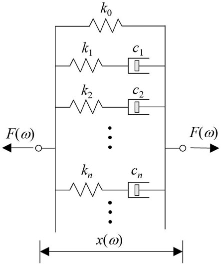
Figure 2. Biot’s model.
The transfer function obtained from the deformation x to the resistive force Fj of the jth branch of Biot’s model is:
where kj, cj, and rj = kj/cj are the stiffness, damping coefficient, and relaxation parameter of the Maxwell element, respectively.
The real and imaginary parts of the dynamic stiffness are referred to as the storage and loss stiffnesses, respectively. The storage stiffness is identical to the conventional stiffness. The product of the loss stiffness and deformation yields the resistive force, the amplitude and phase of which are proportional to the deformation and are in phase with the velocity, respectively. Thus, the loss stiffness is related to energy loss.
[Storage stiffness]
[Loss stiffness]
Figure 3A shows how Biot’s model realizes constant loss stiffness characteristics at high frequencies. As indicated by the solid lines, the loss stiffness of the jth branch reaches its maximum value (indicated by red circles) of kj/2 at angular frequency ω = rj.
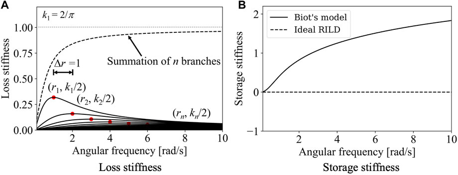
Figure 3. Dynamic stiffness of Biot’s model. (A) Loss stiffness. (B) Storage stiffness.
When the stiffness and damping coefficient of each branch are arranged such that
the lowest relaxation parameter and jth damping coefficient are
Accordingly, the dynamic stiffness of Biot’s model
Furthermore, when Δr → 0,
Figure 3A presents the loss stiffness of Biot’s model when the stiffnesses and relaxation parameters are determined as follows:
Although the loss stiffness exhibits frequency dependency at low frequencies, it becomes almost independent of the frequency at high frequencies.
Figure 3B presents a comparison of the storage stiffness of Biot’s model and ideal RILD when k0 = 0. The storage stiffness of Biot’s model increased with frequency, while that of the ideal RILD was constant, irrespective of the frequency. This is owing to the causality requirement that bounds the real and imaginary parts of the dynamic stiffness, which is known as the Kramers–Kronig relationship (Booij and Thoone, 1982). The causality of Biot’s model results in the addition of stiffness when it is incorporated into a structure.
Herein, we propose a novel causal model to approximate ideal RILD. The model comprises infinite branches of any mechanical device in a second-order physical system connected in parallel, as shown in Figure 4, where s is the Laplace variable.
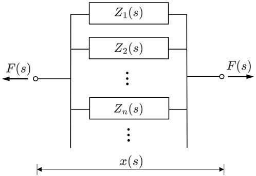
Figure 4. Proposed causal model of RILD.
The dynamic stiffness of a second-order device can be defined as a bi-proper transfer function:
where r and k are the frequency and stiffness dimensions, respectively. a1, a2, b1, b2, and b3 are the dimensionless parameters to be determined.
Let j denote the jth branch, where the dynamic stiffness of the proposed model written in the frequency domain is the summation of all the branches.
Here we assume that the relaxation parameters are distributed with a uniform interval of Δr = rj+1 − rj (j = 1, 2, ⋯) starting from a small value r1 = ɛ. Accordingly, the stiffness of the jth branch is
Based on these definitions, the dynamic stiffness of this model can be expressed as follows:
The sum is then substituted into the integration as follows:
Partial fraction decomposition of the integrand yields
where Δ1 and Δ2 are the roots of the denominator
and A, B, and C can be represented using the roots as follows:
Subsequent to integration and simplification, Eq. 14 is reduced to
Hereafter, we exclusively examine the imaginary part of dynamic stiffness (loss stiffness).
When Δ1 and
where we used the following relationship:
Eq. 18 clearly shows that, when ω ≫ɛ or ɛ → 0, the loss stiffness approaches the constant value k1π.
For the case in which Δ1 and Δ2 are complex-valued, B and C are also complex-valued. It should be noted that the pairs of Δ1 and Δ2 and B and C are conjugate pairs. For further simplification, the following equations are introduced:
where α1, α2, β1, and β2 are real-value constants. Eq. 17 is expanded by separating the real and imaginary parts as follows:
which is further reduced to:
Eq. 22 demonstrates that the loss stiffness approaches a constant value as the excitation angular frequency ω increases, which proves that the proposed model can be an excellent approximation of the ideal RILD in terms of loss stiffness.
As previously mentioned, Biot’s model comprises infinite Maxwell elements arranged in parallel. The dynamic stiffness of Biot’s model in the frequency domain is a summation of those of all branches:
where rj represent the relaxation frequency of the jth branch. It should be noted that the proposed model is reduced to Biot’s model when a1, b1 = 0 and a2, b2, b3 = 1.
Because the proposed second-order causal model encompassing Biot’s model has more parameters than Biot’s model, it offers a solution for reducing undesirable storage stiffness, as discussed in the following section.
An inerter (Smith, 2002) is a two-node mechanical device, the application of which in civil structures has been investigated for decades. The inertial resistive force generated by an inerter is proportional to the relative acceleration between its two nodes. Its physical realization usually involves the amplification of the physical mass using fluid (Kawamata, 1989; Kawamata, 1987; Nakamura et al., 1988; Wang et al., 2011; Swift et al., 2013; Nakaminami et al., 2017; Liu et al., 2018; Zhang et al., 2018; De Domenico et al., 2019), a leverage (Sone et al., 1998), rack and pinion (Smith, 2002; Saitoh, 2012; Pietrosanti et al., 2021), and ball screw (Arakaki et al., 1999a; b; Hwang et al., 2007; Watanabe et al., 2012; Xie et al., 2019; Xue et al., 2020; Kang et al., 2023; Li et al., 2023). Researchers have investigated various configurations of inerter, spring, and damper for the protection of civil structures against earthquakes and wind (Ikago et al., 2012; Giaralis and Petrini, 2017; Marian and Giaralis, 2017; Pan and Zhang, 2018; Jia et al., 2023; Kang and Ikago, 2023).
As shown in Figure 5A, a parallel arrangement of an inerter and a damper yields a compact device that can provide thousands of tons of inertance, which is sufficient for structural control. The connection of a spring element to the device configures a tuned-mass-damper-like (TMD-like) system, designated as a TVMD (Ikago et al., 2012). In contrast to a conventional TMD, a mass element (inerter) is arranged in parallel to the damper in a TVMD, as shown in Figure 5B. To the best of our knowledge, inerter-based seismic control systems have been applied to real-life building structures only in Japan (Sugimura et al., 2012; Architectural Institute of Japan, 2014; Ishii et al., 2014; Ogino and Sumiyama, 2014).
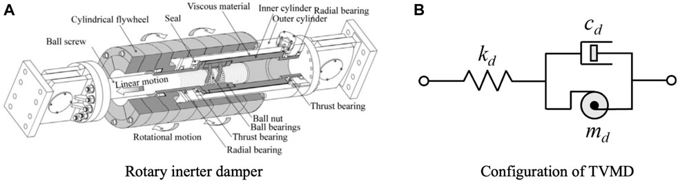
Figure 5. Rotary inerter damper and tuned viscous mass damper. (A) Rotary inerter damper. (B) Configuration of TVMD.
The dynamic stiffness of TVMD can be expressed as follows:
where r = kd/cd and
The dynamic stiffness of a TVMD single branch shown in Eq. 25 is similar to Eq. 9. It is easy to infer that the infinite branches of TVMDs will also be a physical realization of the proposed model. To prove this, we first express the dynamic stiffness of the infinite branches of TVMDs as follows:
The springs and inerters in the model resulted in the formation of infinite oscillators. Herein, we introduce a damping ratio
On comparing the above equation with Eq. 10, the parameters can be identified as a1, b1 = 1 and a2, b2, b3 = 4ζ2 for all branches. The dynamic stiffness of the infinite TVMDs can then be derived as
where B, C, Δ1, and Δ2 are defined as
B, C, Δ1, and Δ2 have complex values when 0 < ζ < 1; however, they have real values when ζ > 1. As previously discussed, in either case, this model can serve as an approximation of an ideal RILD model.
This section presents an example to demonstrate the advantages of the proposed model over Biot’s model. The loss stiffness in Biot’s model monotonically increases over the entire frequency range [0, ∞] and approaches
The lower bound of the relaxation parameter for Biot’s model ɛB was determined such that the maximum error in the loss stiffness at frequencies greater than 1 rad/s was less than 1%.
An iteration shows that ɛB = 0.015 satisfies Eq. 31. For the proposed model, the required ζ = 0.5 when we set kd,1 to
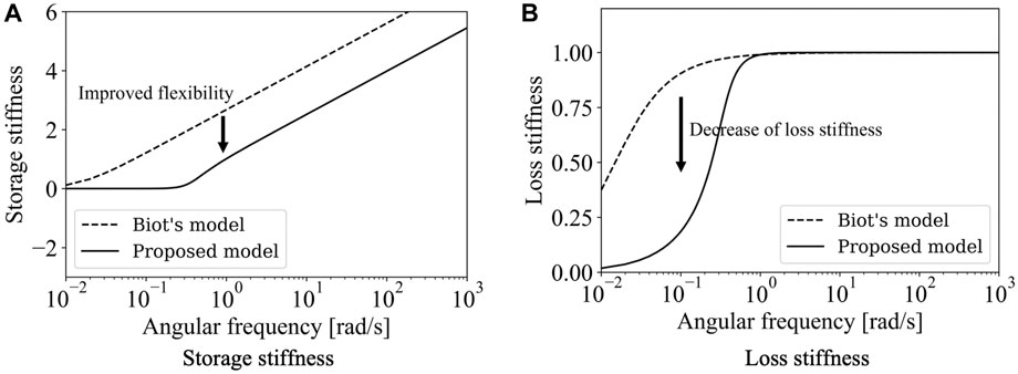
Figure 6. Dynamic stiffness of Biot’s and the proposed models. (A) Storage stiffness. (B) Loss stiffness.
The proposed model requires infinite TVMDs arranged in parallel to causally approximate RILD over all the frequencies. Nonetheless, the number of required branches can be significantly reduced by limiting the frequency band in which a constant loss stiffness is achieved, which is preferable for practical structural design.
The loss stiffness of a single TVMD branch is given as
To solve for
Therefore, the peak value of the loss stiffness is
Figure 7A presents the shape of the TVMD loss stiffness function and its peak value coordinates.
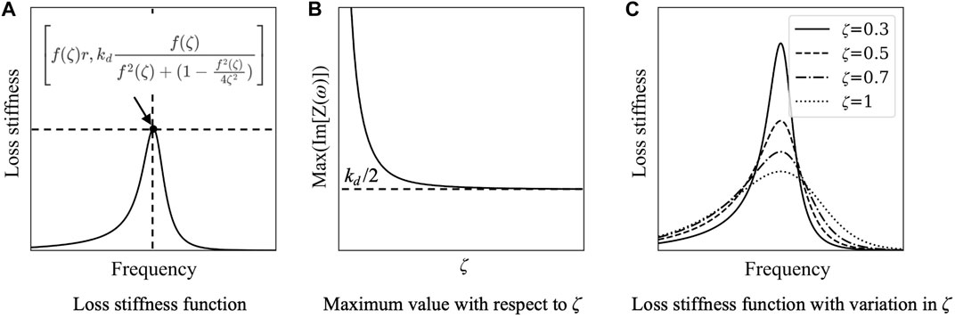
Figure 7. Mathematical properties of loss stiffness function for a single TVMD branch. (A) Loss stiffness function. (B) Maximum value with respect to ζ. (C) Loss stiffness function with variation in ζ.
Eq. 34 indicates that the peak value of the loss stiffness is proportional to the stiffness of the branch kd. As shown in Figure 7B, the peak value decreases and approaches kd/2 as the damping ratio of the branch ζ increases.
Figure 7C shows that the shape of the loss stiffness function becomes longer and narrower as ζ decreases.
Herein, we denote a second-order causal RILD device comprising n branches of TVMDs as n-TVMD. For an n-TVMD, the frequency band in which the loss stiffness is specified is limited to [ωℓ, ωu].
Regarding the distribution of the relaxation parameters, Genta and Amati (2009) adopted geometric progression. Liu and Ikago (2021b) adopted fundamental natural frequencies as the relaxation parameters to avoid the parameters of their proposed device to become negative values. This study adopted a uniform distribution as follows:
The number of branches n should be chosen properly to avoid negative parameters of the branches.
All the branches share the same damping ratio ζ, and the jth branch is designed to exhibit a peak value at frequency λj. Thus, from Eq. 33,
Let Zn (ω; ωℓ, ωu) denote the dynamic stiffness of the n-TVMD with a target frequency range [ωℓ, ωu], and the loss stiffness is
We consider incorporating n-TVMD into a base-isolation layer, the isolator stiffness of which is ks, and the target loss stiffness to be imparted is ηks. Accordingly, the following condition is imposed to realize a constant loss stiffness within the frequency region of interest.
When we define βj and Qj (λk) as follows:
Eq. 38 can be rewritten as
Figure 8 illustrates how constant loss stiffness is realized in a four-TVMD model in the specified frequency range. The dashed lines represent the loss stiffness of each branch. The summation of the loss stiffnesses of all the branches attains a constant value stiffness within the target frequency range, as shown by the solid line.

Figure 8. Four branch example.
On solving Eq. 40 with respect to {βj}, we obtain
A greater number of branches of TVMDs causes the loss stiffness to become flatter when ζ is fixed, as shown in Figure 9A.
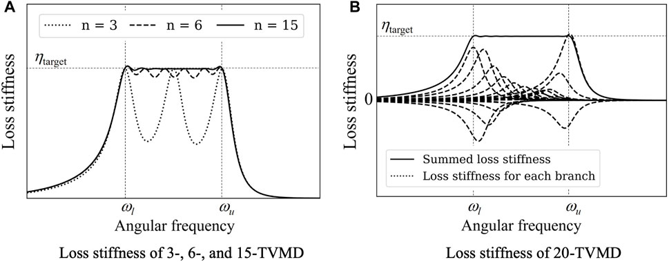
Figure 9. Loss stiffness of n-TVMD. (A) Loss stiffness of 3-, 6-, and 15-TVMD. (B) Loss stiffness of 20-TVMD.
However, some of the βj values become negative when λj are uniformly distributed and n exceeds a certain value, as shown in Figure 9B. The maximum n required to maintain βj as positive, thereby ensuring the feasibility of the n-TVMD is denoted as nu, which can be reduced by increasing ζ.
Fewer branches of TVMD are preferable in practical structural design, which is realized at the expense of accuracy in approximating the constant loss stiffness. Discussions on achieving a compromise between feasibility and accuracy when designing an n-TVMD are presented in the next section.
To elucidate the influence of the target frequency range [ωℓ, ωu] on the control efficacy of an n-TVMD, we examined an SDOF structure equipped with an n-TVMD, as shown in Figure 10.
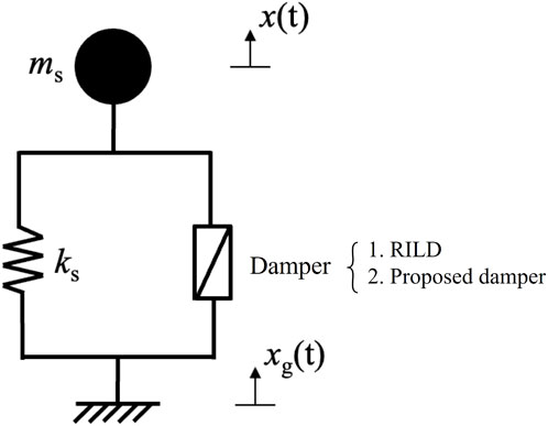
Figure 10. SDOF structure equipped with n-TVMD or RILD.
The transfer functions from the ground acceleration
where the superscript j represents the damping element incorporated into the structure; j = 1 and 2 correspond to RILD and proposed models, respectively.
Thus,
Figures 11A–C, present the peak values with respect to ω of the transfer functions of the SDOF structure containing the n-TVMD system (j = 2) normalized by those of the SDOF structure containing RILD (j = 1). The horizontal axes indicate the lower- and upper-bound frequencies normalized by the fundamental angular frequency. The vertical axes indicate the peak values of (a) displacement, (b) acceleration, and (c) control force transfer functions normalized by those of RILD. The n-TVMD exhibits the best performance with a lower-bound frequency near ω0, while the displacement mitigation performance is close to that of RILD as long as the lower-bound frequency is lower than ω0. When the upper bound frequency exceeds twice the fundamental frequency, the performance of the n-TVMD approaches that of RILD.
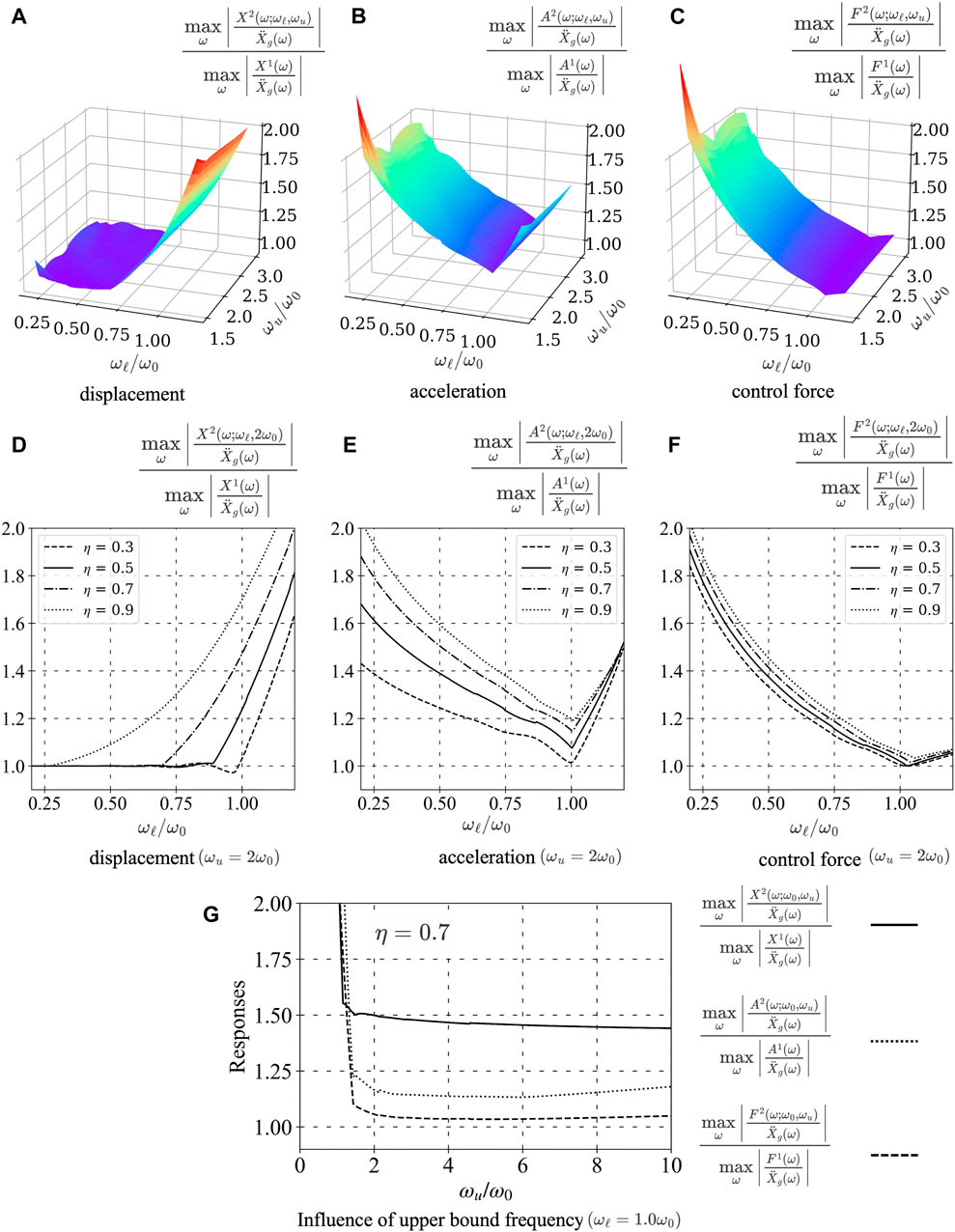
Figure 11. Comparison of responses of ideal RILD and proposed model. (A,D) Displacement. (B,E) Acceleration. (C,F) Control force. (G) Influence of upper bound frequency.
Figures 11D–F, present the peak values of the transfer functions with respect to the lower-bound frequency as the loss factor is varied when the upper-bound frequency is fixed at twice the fundamental natural frequency. The upper bound of the lower-bound frequency ωℓ, which exhibits a displacement control performance similar to that of RILD, decreases as the loss factor increases, as shown in Figure 11D. However, the optimal lower-bound frequencies that minimize the acceleration and control force remain almost constant. Utilizing this characteristic can minimize the acceleration and damping force responses, rendering them closer to an ideal RILD. The increased displacement response can be managed with a higher loss factor to satisfy design requirements.
The above observations suggest that setting ωℓ = ω0 is a viable option for n-TVMD to realize a control performance similar to that of an ideal RILD when the target loss factor η is relatively low. Figure 11G presents the cross-sections of Figures 11A–C along ωℓ = ω0. As discussed in Section 3.3, the proposed system improves the storage stiffness more than the conventional causal RILD model [see Figure 6A], resulting in a better approximation of the floor response acceleration and damper resistive force, especially when ωu > 2ω0. However, this is attained at the expense of the displacement response owing to the reduced loss stiffness at low frequencies [see Figure 6B].
Considering that a lower value of ωu necessitates a smaller number of branches, thus resulting in enhanced feasibility and cost efficiency, we suggest setting ωu = 2ω0 for SDOF systems.
Figure 12 presents the parameter design flow for an n-TVMD. The damping ratio ζ and target angular frequency range [ωℓ, ωu] are given first. Herein, ζ = 0.25, and the target angular frequency range is [ω0, 2ω0], where ω0 is the fundamental angular frequency of the controlled structure. The first iteration is performed to identify the loss factor η with the maximum feasible number of branches nu that satisfy the design criteria. In this study, we began with an initial estimate of the value of η, determined nu and βj, and performed a time–history analysis. The η value was gradually increased until the design criteria were satisfied. In the second iteration, the number of branches n was decremented until the minimum n satisfying the design criteria was reached.
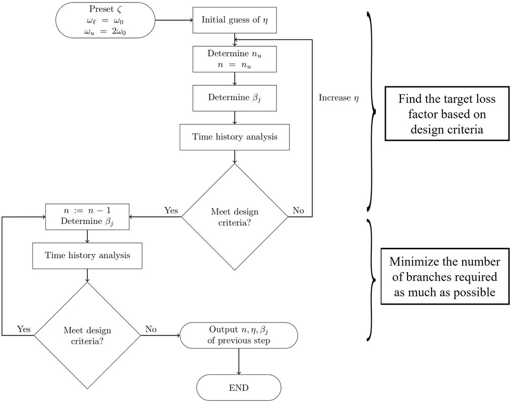
Figure 12. Parameter design flowchart.
Figure 13 presents the analytical model of an example multi-degree-of-freedom (MDOF) base-isolated structure with its properties listed in Figure 13B. The isolator horizontal stiffness was designed such that the fundamental undamped natural period was 4.0 s, following the base-isolation design practice in Japan.
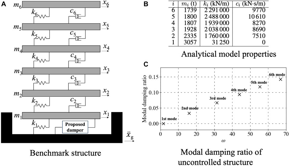
Figure 13. Analytical model information. (A) Benchmark structure. (B) Analytical model properties. (C) Modal damping ratio of uncontrolled structure.
The mass-proportional portion of the Rayleigh damping imparts undesirable damping to the first mode of the isolated structure beyond that provided by the dampers in the isolation layer, thus resulting in an underestimated seismic response, as reported in Hall (2006). Therefore, stiffness-proportional damping was adopted in this study, with a damping ratio of 2% assigned to the first mode of the superstructure with a fixed base (Ryan and Polanco, 2008; Anajafi et al., 2020). The inherent damping at the isolation layer is ignored. Figure 13C presents the modal damping ratios of the structure with no damping devices incorporated into the isolation layer.
This section presents an investigation of the high-mode effect on the performance of the n-TVMD incorporated into the example MDOF base-isolated structure.
Here, the loss factor is η = 0.7. In the case of the target frequency range, two cases, [ω0, 2ω0] and [ω0, 50ω0], were investigated. The upper-bound frequency of the former case was the same as that of the SDOF case. The latter case was a control, the target angular frequency range of which includes all fundamental natural angular frequencies of the entire structure. The former and latter cases comprised 5 and 26 branches, respectively. Figures 14A, B present the dynamic stiffnesses of the 5- and 26-TVMD systems, respectively. It should be noted that narrowing the target frequency band reduces the undesirable storage stiffness at high frequencies.
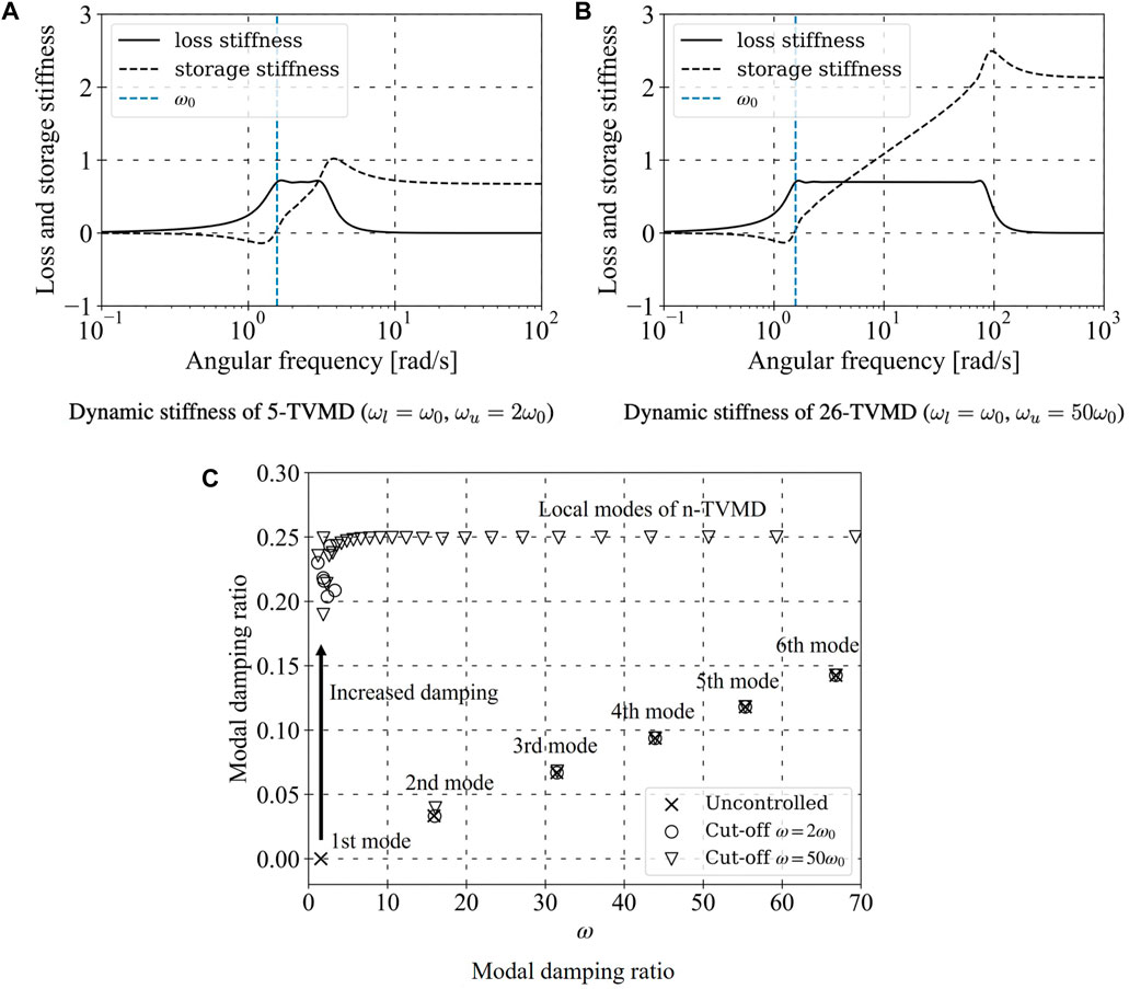
Figure 14. Analytical model equipped with 5-TVMD and 26-TVMD. (A) Dynamic stiffness of 5-TVMD. (B) Dynamic stiffness 26-TVMD. (C) Modal damping ratio.
Figure 14C presents the modal damping ratios of the uncontrolled structure and cases comprising the 5- and 26-TVMD systems. The ×, ◦, and ▽ notations represent the uncontrolled and 5- and 26-TVMD controlled cases, respectively. The n-TVMDs adds n degrees of freedom, thus resulting in n additional modes owing to the inerters. The ◦ and ▽ notations, which are distributed at a damping ratio of approximately 0.25, represent the damping ratios of the locally independent modes of TVMD branches. The damping ratio of the first mode was increased by n-TMVDs, while those of the higher modes remained almost constant. This is because the n-TVMDs are activated by the isolator displacement, which is dominated by the first mode.
Figure 15A presents a comparison of the participation mode vectors of the uncontrolled, 5-TVMD controlled (ωu = 2ω0), and 26-TVMD controlled (ωu = 50ω0) cases. This figure indicates that an increase in the number of branches n to include the high-mode frequencies only slightly improves the seismic response displacement because the participation of high modes is limited.
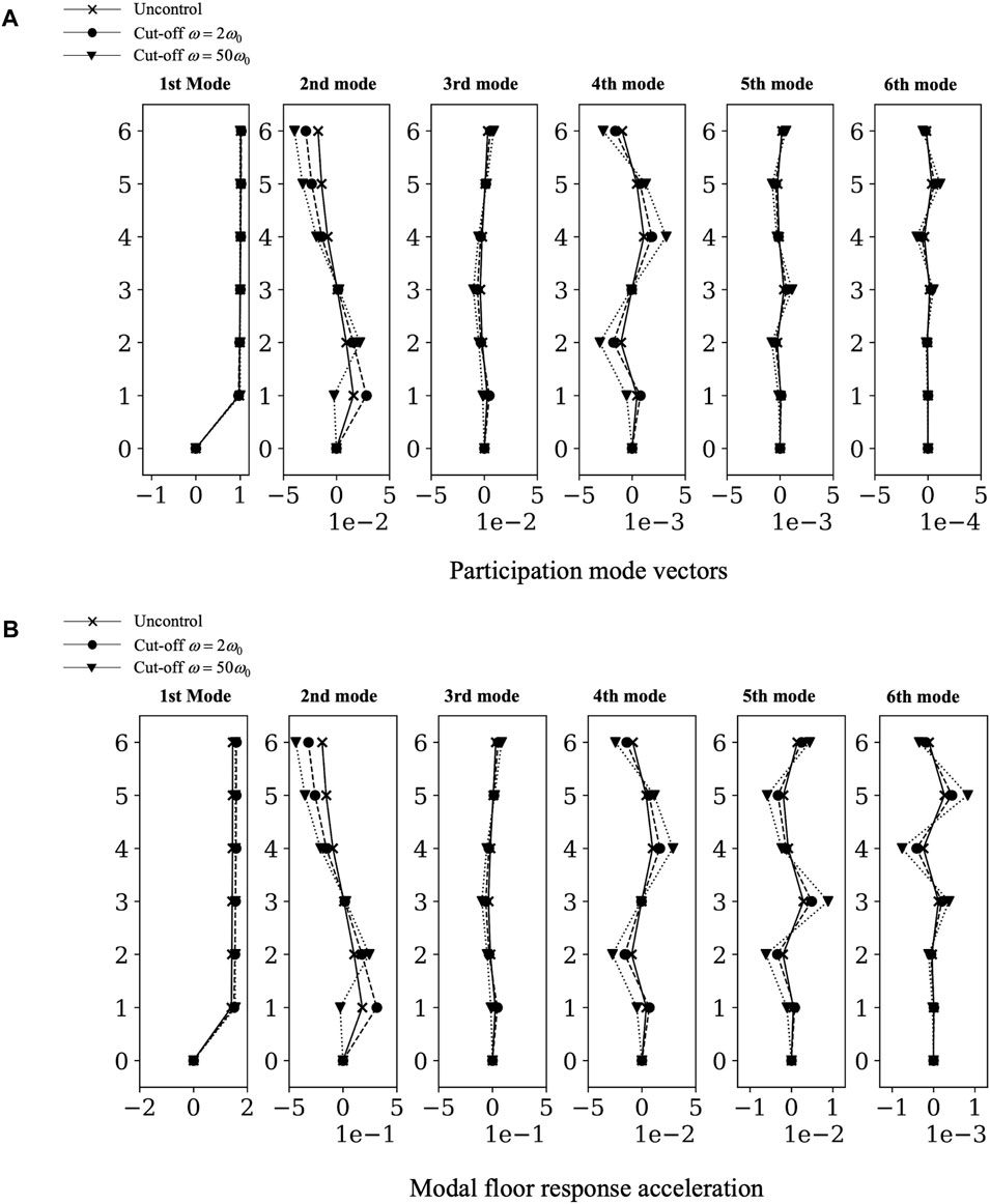
Figure 15. Participation mode vectors and modal floor response acceleration. (A) Participation mode vectors. (B) Modal floor response acceleration.
Supplementary Figure S1 presents the acceleration spectrum for the type-two surface subsoil provided in the building seismic design code of Japan. Modal floor response accelerations, as products of the participation mode vectors and acceleration spectra, are presented in Figure 15B. In contrast to the displacement response, the high modes—and especially the second mode—have a significant effect on the floor response accelerations. The addition of n-TVMDs increases the floor response acceleration. Moreover, widening the target frequency band increases the floor response accelerations.
Thus, the selection of the upper bound of the target frequency as twice the fundamental natural angular frequency is a better option for mitigating floor response acceleration.
Three recorded and three synthetic ground motions were employed as design earthquakes, in accordance with the practice in Japan. The three recorded ground motions were scaled such that their peak ground velocities (PGVs) were 0.5 m/s. Table 1 lists the details of these ground motions. The synthetic ground motions were generated such that their response acceleration spectra were compatible with the design spectrum, as shown in Supplementary Figure S1. Each ground motion is identified by a number, as shown in Table 1.
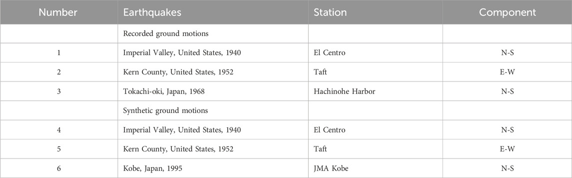
Table 1. Ground motions.
For comparison, a base-isolated structure comprising ideal RILD, LVD, and the proposed model (n-TVMD) was examined. These three damping systems were designed such that the maximum isolator displacement yielded by the six ground motions was 0.3 m. The condition of the isolator displacement was employed as the design criterion for the design flow presented in Figure 12. Following the design process presented in the previous section, the number of TVMDs was reduced to three. Table 2 lists the designed properties of the damping models that satisfy this criterion.
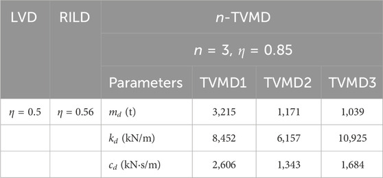
Table 2. Damper properties.
Supplementary Figure S2A presents the time–history seismic responses of the three systems under No. 6 ground motion (synthetic ground motion with the 1995 JMA Kobe record phase property). The diagram shows that the ideal RILD has a clear advantage in protecting seismic isolation structures, and the performance of the proposed model lies between RILD and LVD. The maximum values from the time-history results of the damping force and damper stroke demonstrate the feasibility of the proposed model in practical engineering applications. Supplementary Figures S2C, S2D present a comparison of their maximum responses under each ground motion. The No. 6 ground motion yielded the highest responses in terms of isolator displacement and rooftop response acceleration. Thus, the No. 6 ground motion was used to realize the damping system design, and both systems yielded a maximum isolator displacement of 0.3 m for the No. 6 ground motion.
Supplementary Figure S2B presents a description of the relationship between the maxima of the isolator displacement and floor response acceleration yielded by the RILD, LVD, and proposed damping models subjected to six ground motions. The isolator displacement decreased as the loss factor of the damping systems increased, while an excessively large loss factor compromises the floor response acceleration in the LVD and proposed models. The proposed system realizes a similar response mitigation effect to the RILD if an isolator displacement of 0.4 m or greater is allowed. There are no feasible designs for LVD in the gray area, i.e., the area in which the maximum allowable isolator displacement and rooftop acceleration are less than 0.36 m and 1.43 m/s2, respectively. Nonetheless, there are feasible designs for RILD and the proposed model.
The proposed model comprises multiple branches of TVMDs. A TVMD is a commercially available device that has been applied to real-life building structures in Japan (Sugimura et al., 2012; Ishii et al., 2014; Ogino and Sumiyama, 2014). Supplementary Figure S3A illustrates the installation of a TVMD in a building frame (Sugimura et al., 2012). The inertance, stiffness, and maximum resistive force of the TVMD device are 5,400 tons, 7,300 kNm/s, and 68,600 kN/m, and 1,200 kN, respectively. Thus, the parameters of the TVMD devices listed in Table 2 fall within the feasible range. When incorporating the proposed device into a seismic isolation layer, the rotary inerter dampers are connected to a laminated rubber device to provide a tuned stiffness, as shown in Supplementary Figure S3B.
This study focused exclusively on theoretical and numerical analyses. Therefore, experimental studies using small- or full-scale specimens should be conducted in the future. In addition, because the rotary inerter damper is a relatively new device that has not yet been widely adopted, its cost is considered a challenge.
The amplitude and phase of the RILD resistive force were proportional to the displacement and in phase with the velocity, respectively. This resulted in the benefit of the direct control capability of the seismic response displacement in a low-frequency structure such as a seismically isolated building.
This study was motivated by one of the most successful causal RILD models, i.e., Biot’s model, which comprises infinite Maxwell elements with first-order dynamic stiffness. The dynamic stiffness of each branch was expanded to the second order. Because a branch of second-order dynamic stiffness can be decomposed into two branches with first-order dynamic stiffness, it was found that the second-order causal RILD model encompasses Biot’s model, which suggests that the proposed system can improve the storage stiffness while maintaining constant loss stiffness characteristics.
As a physical device used for realizing the proposed second-order branch, the TVMD, which is a commercially available device, is employed. The negative-stiffness effect of an inerter in a TVMD branch successfully reduces the undesirable storage stiffness compared to Biot’s model.
By limiting the target frequency range in which a constant loss stiffness is achieved, the required number of branches is significantly reduced, thus enhancing the feasibility of the proposed device.
An analytical example was used to demonstrate that the proposed device approximated the performance of RILD well when the maximum allowable isolator displacement was 0.4 m or greater. The performance of the proposed device degraded when the demand for isolator displacement mitigation became more severe; nevertheless, it outperformed LVD. Moreover, the properties of the proposed device, i.e., the inertance, damping coefficients, stiffness, and maximum resistive force were in the realizable range.
The raw data supporting the conclusion of this article will be made available by the authors, without undue reservation.
BW: Funding acquisition, Investigation, Writing–original draft, Writing–review and editing. KI: Supervision, Writing–original draft, Writing–review and editing. SK: Conceptualization, Methodology, Validation, Writing–original draft, Writing–review and editing.
The author(s) declare that financial support was received for the research, authorship, and/or publication of this article. This work was supported by the Support for Pioneering Research Initiated by the Next-Generation Program (Grant Number. JPMJSP2114) provided by the Japan Science and Technology Agency.
The authors declare that the research was conducted in the absence of any commercial or financial relationships that could be construed as a potential conflict of interest.
All claims expressed in this article are solely those of the authors and do not necessarily represent those of their affiliated organizations, or those of the publisher, the editors and the reviewers. Any product that may be evaluated in this article, or claim that may be made by its manufacturer, is not guaranteed or endorsed by the publisher.
The Supplementary Material for this article can be found online at: https://www.frontiersin.org/articles/10.3389/fbuil.2024.1411170/full#supplementary-material
Anajafi, H., Medina, R. A., and Santini-Bell, E. (2020). Effects of the improper modeling of viscous damping on the first-mode and higher-mode dominated responses of base-isolated buildings. Earthq. Eng. Struct. Dyn. 49, 51–73. doi:10.1002/eqe.3223
Arakaki, T., Kuroda, H., Arima, F., Inoue, Y., and Baba, K. (1999a). Development of seismic devices applied to ball screw: Part 1 basic performance test of RD-series. AIJ J. Technol. Des. 5, 239–244. doi:10.3130/aijt.5.239_1
Arakaki, T., Kuroda, H., Arima, F., Inoue, Y., and Baba, K. (1999b). Development of seismic devices applied to ball screw: Part 2 performance test and evaluation of RD-series. AIJ J. Technol. Des. 5, 265–270. doi:10.3130/aijt.5.265
Architectural Institute of Japan (2007). Structural response and performance for long period seismic gound motions, vol. 366 (MARUZEN)
Architectural Institute of Japan (2014) Intelligible guide to structural control. (in Japanese) (MARUZEN).
Biot, M. A. (1958). “Linear thermodynamics and the mechanics of solids,” in Proceedings of the third US national congress of applied mechanics (America: American Society of Mechanical Engineers).
Booij, H., and Thoone, G. (1982). Generalization of kramers-kronig transforms and some approximations of relations between viscoelastic quantities. Rheol. Acta 21, 15–24. doi:10.1007/bf01520701
Caughey, T. (1962). Vibration of dynamic system with linear hysteretic damping (linear theory). Proc. 4th U. S. Natl. Congr. Appl. Mech. 1962, 87–97.
Crandall, S. (1991). The hysteretic damping model in vibration theory. Proc. Institution Mech. Eng. Part C Mech. Eng. Sci. 205, 23–28. doi:10.1243/pime_proc_1991_205_086_02
De Domenico, D., Deastra, P., Ricciardi, G., Sims, N. D., and Wagg, D. J. (2019). Novel fluid inerter based tuned mass dampers for optimised structural control of base-isolated buildings. J. Frankl. Inst. 356, 7626–7649. doi:10.1016/j.jfranklin.2018.11.012
Genta, G., and Amati, N. (2009). On the equivalent viscous damping for systems with hysteresis. Mecc. Dei Solidi 32, 21–43.
Giaralis, A., and Petrini, F. (2017). Wind-induced vibration mitigation in tall buildings using the tuned-mass-damper-inerter. J. Struct. Eng. 143, 04017127. doi:10.1061/(asce)st.1943-541x.0001863
Hall, J. F. (2006). Problems encountered from the use (or misuse) of Rayleigh damping. Earthq. Eng. Struct. Dyn. 35, 525–545. doi:10.1002/eqe.541
Hwang, J.-S., Kim, J., and Kim, Y.-M. (2007). Rotational inertia dampers with toggle bracing for vibration control of a building structure. Eng. Struct. 29, 1201–1208. doi:10.1016/j.engstruct.2006.08.005
Ikago, K., and Inoue, N. (2014). “Behavior of rate-independent linear damping incorporated into long-period structures subjected to strong ground motions,” in Proceedings of the 6th world conference on structural control and monitoring, Spain, 15-17 July 2014 (IEEE), 1116–1124.
Ikago, K., Saito, K., and Inoue, N. (2012). Seismic control of single-degree-of-freedom structure using tuned viscous mass damper. Earthq. Eng. Struct. Dyn. 41, 453–474. doi:10.1002/eqe.1138
Ilgeigi, S., Jahanpur, J., and Farshidianfar, A. (2012). A novel scheme for nonlinear displacement-dependent dampers. Nonlinear Dynamcics 70, 421–434. doi:10.1007/s11071-012-0465-4
Inaudi, J. (1997). Modulated homogeneous friction: a semi active damping strategy. Earthq. Eng. Struct. Dyn. 26, 361–376. doi:10.1002/(sici)1096-9845(199703)26:3<361::aid-eqe648>3.3.co;2-d
Ishii, M., Kazama, H., Miyazaki, K., and Murakami, K. (2014). “Application of tuned viscous mass damper to super-high-rise buildings,” in Proceedings of the 6th World Conference of Structural Control and Health Monitoring, Barcelona, Sapin, 15-17 July 2014 (IEEE), 2825–2833.
Jia, R., Ji, X., Cheng, Y., and Ikago, K. (2023). Seismic response control of core wall structures using tuned viscous mass damper (tvmd) outriggers. Eng. Struct. 292, 116546. doi:10.1016/j.engstruct.2023.116546
Kang, J., and Ikago, K. (2023). Seismic control of multi-degree-of-freedom structures using a concentratedly arranged tuned viscous mass damper. Earthq. Eng. Struct. Dyn. 52, 4708–4732. doi:10.1002/eqe.3977
Kang, J., Xue, S., Xie, L., Tang, H., and Zhang, R. (2023). Multi-modal seismic control design for multi-storey buildings using cross-layer installed cable-bracing inerter systems: Part 1 theoretical treatment. Soil Dyn. Earthq. Eng. 164, 107639. doi:10.1016/j.soildyn.2022.107639
Kawamata, S. (1987). “Accelerated liquid mass damper and principles of structural vibration control,” in Transactions of the International Conference on Structural Mechanics in Reactor Technology (Lausanne), USA, 17-21 August 1987 (IEEE), 737–742.
Keivan, A., Zhang, R., Keivan, D., Phillips, B. M., Ikenaga, M., and Ikago, K. (2020). Rate-independent linear damping for the improved seismic performance of inter-story isolated structures. J. Earthq. Eng. 26, 793–816. doi:10.1080/13632469.2019.1693444
Kelly, J., Beucke, K., and M, S. S. (1980). Experimental testing of a friction damped aseismic base isolation system with fail-safe characteristics. NASA STI/Recon Tech. Rep. N. 1980 81, 26304.
Li, D., Ikago, K., and Yin, A. (2023). Structural dynamic vibration absorber using a tuned inerter eddy current damper. Mech. Syst. Signal Process. 186, 109915. doi:10.1016/j.ymssp.2022.109915
Liu, W., and Ikago, K. (2021a). Feasibility study of a passive rate-independent damping device for the seismic protection of low-frequency structures. Structures 34, 2499–2514. doi:10.1016/j.istruc.2021.09.005
Liu, W., and Ikago, K. (2021b). Feasibility study of the physical implementation of rate-independent linear damping for the protection of low-frequency structures. J. Build. Eng. 44, 103319. doi:10.1016/j.jobe.2021.103319
Liu, W., and Ikago, K. (2022a). Causal implementation of rate-independent linear damping for the seismic protection of low-frequency structures. Structures 35, 274–288. doi:10.1016/j.istruc.2021.10.095
Liu, W., and Ikago, K. (2022b). Feasibility of physical implementation of rate-independent linear damping to protect multistory low-frequency structures. J. Sound Vib. 528, 116893. doi:10.1016/j.jsv.2022.116893
Liu, W., and Ikago, K. (2022c). Performance of a passive rate-independent damping device in a seismically isolated multistory building. Struct. Control Health Monit. 29, e2941. doi:10.1002/stc.2941
Liu, W., Ikago, K., Wu, Z., and Fukuda, I. (2022). Modified tuned Maxwell–Wiechert model for improving seismic performance of base-isolated structures. J. Build. Eng. 54, 104616. doi:10.1016/j.jobe.2022.104616
Liu, X., Jiang, J. Z., Titurus, B., and Harrison, A. (2018). Model identification methodology for fluid-based inerters. Mech. Syst. Signal Process. 106, 479–494. doi:10.1016/j.ymssp.2018.01.018
Lu, Z., Wang, Z., Zhou, Y., and Lu, X. (2018). Nonlinear dissipative devices in structural vibration control: a review. J. Sound Vib. 423, 18–49. doi:10.1016/j.jsv.2018.02.052
Luo, H., and Ikago, K. (2021). Unifying causal model of rate-independent linear damping for effectively reducing seismic response in low-frequency structures. Earthq. Eng. Struct. Dyn. 50, 2355–2378. doi:10.1002/eqe.3450
Luo, H., Ikago, K., Chong, C., Keivan, A., and Phillips, B. (2019). Performance of low-frequency structures incorporated with rate-independent linear damping. Eng. Struct. 181, 324–335. doi:10.1016/j.engstruct.2018.12.022
Makris, N. (1997). Causal hysteretic element. J. Eng. Mech. 123, 1209–1214. doi:10.1061/(asce)0733-9399(1997)123:11(1209)
Marian, L., and Giaralis, A. (2017). The tuned mass-damper-inerter for harmonic vibrations suppression, attached mass reduction, and energy harvesting. Smart Struct. Syst. 19, 665–678. doi:10.12989/sss.2017.19.6.665
Nakaminami, S., Kida, H., Ikago, K., and Inoue, N. (2017). “Dynamic testing of a full-scale hydraulic inerter-damper for the seismic protection of civil structures,” in Proceeding of the 7th International Conference on Advances in Experimental Structural Engineering, Pavia, Italy, 6th – 8th September – 2017 (IEEE), 57–79.
Nakamura, Y., Watanabe, H., and Kawamata, S. (1988). “Seismic response control of structures by accelerated liquid mass damper,” in Proceedings of the 9th World Conference on Earthquake Engineering, Japan, Jul 2024 (Tokyo-Kyoto), 785–790.
Ogino, M., and Sumiyama, T. (2014). “Structural design of a high-rise building using tuned viscous mass dampers installed across three consecutive sotreys,” in Proceedings of the 12th International Conference on Computational Structures Technology, Naples, Italy, August 24 ∼ 25, 2024 (IEEE), 225.
Pan, C., and Zhang, R. (2018). Design of structure with inerter system based on stochastic response mitigation ratio. Struct. Control Health Monit. 25, e2169. doi:10.1002/stc.2169
Pietrosanti, D., De Angelis, M., and Giaralis, A. (2021). Experimental seismic performance assessment and numerical modelling of nonlinear inerter vibration absorber (iva)-equipped base isolated structures tested on shaking table. Earthq. Eng. Struct. Dyn. 50, 2732–2753. doi:10.1002/eqe.3469
Ryan, K. L., and Polanco, J. (2008). Problems with Rayleigh damping in base-isolated buildings. J. Struct. Eng. 134, 1780–1784. doi:10.1061/(asce)0733-9445(2008)134:11(1780)
Saitoh, M. (2012). On the performance of gyro-mass devices for displacement mitigation in base isolation systems. Struct. Control Health Monit. 19, 246–259. doi:10.1002/stc.419
Smith, M. (2002). Synthesis of mechanical networks: the inerter. IEEE Trans. Automatic Control 47, 1648–1662. doi:10.1109/tac.2002.803532
Sone, A., Yamamoto, S., and Masuda, A. (1998) Sliding mode control for building using tuned mass damper with pendulum and lever mechanism during strong earthquake. Copy available on request.
Sugimura, Y., Goto, W., Tanizawa, H., Saito, K., and Ninomiya, T. (2012). “Response control effect of steel building structure using tuend viscous mass damper,” in Proceedings of the 15th International Conference on Earthquake Engineering (Lisbon, Portugal), USA, 24-28 September 2012 (IEEE). Paper ID 0138.
Swift, S., Smith, M., Glover, A., Papageorgiou, C., Gartner, B., and Houghton, N. (2013). Design and modelling of a fluid inerter. Int. J. Control 86, 2035–2051. doi:10.1080/00207179.2013.842263
Wang, F., Hong, M., and Lin, T. (2011). Designing and testing a hydraulic inerter. Proc. Institution Mech. Eng. Part C J. Mech. Eng. Sci. 225, 66–72. doi:10.1243/09544062JMES2199
Watanabe, Y., Ikago, K., Inoue, N., Kida, H., Nakaminami, S., Tanaka, H., et al. (2012). “Full-scale dynamic tests and analytical verification of a force-restricted tuned viscous mass damper,” in Proceedings of the 15th World Conference on Earthquake Engineering (Lisbon, Portugal), China, 24-28 September 2012 (IEEE). ID 1206.
Wu, Z., and Ikago, K. (2024). Feasibility of an inerter-based causal rate-independent damping model for the protection of seismically isolated structures. Struct. (Elsevier) 62, 106271. doi:10.1016/j.istruc.2024.106271
Wu, Z., Liu, W., and Ikago, K. (2023). Feasibility study of a practical causal rate-independent damping device for the improved performance of seismic isolated structures. Eng. Struct. 275, 115305. doi:10.1016/j.engstruct.2022.115305
Xie, L., Ban, X., Xue, S., Ikago, K., Kang, J., and Tang, H. (2019). Theoretical study on a cable-bracing inerter system for seismic mitigation. Appl. Sci. 9, 4096. doi:10.3390/app9194096
Xue, S., Kang, J., Xie, L., Zhang, R., and Xinlei, B. (2020). Cross-layer installed cable-bracing inerter system for MDOF structure seismic response control. Appl. Sci. 10, 5914. doi:10.3390/app10175914
Keywords: rate-independent linear damping, linear hysteretic damping, causality, Biot’s model, low-frequency structure, tuned viscous mass damper
Citation: Wang B, Ikago K and Kezuka S (2024) Causal rate-independent damping device using a rotary inerter damper. Front. Built Environ. 10:1411170. doi: 10.3389/fbuil.2024.1411170
Received: 02 April 2024; Accepted: 30 April 2024;
Published: 30 May 2024.
Edited by:
Michele Palermo, University of Bologna, ItalyCopyright © 2024 Wang, Ikago and Kezuka. This is an open-access article distributed under the terms of the Creative Commons Attribution License (CC BY). The use, distribution or reproduction in other forums is permitted, provided the original author(s) and the copyright owner(s) are credited and that the original publication in this journal is cited, in accordance with accepted academic practice. No use, distribution or reproduction is permitted which does not comply with these terms.
*Correspondence: Kohju Ikago, aWthZ29AaXJpZGVzLnRvaG9rdS5hYy5qcA==
Disclaimer: All claims expressed in this article are solely those of the authors and do not necessarily represent those of their affiliated organizations, or those of the publisher, the editors and the reviewers. Any product that may be evaluated in this article or claim that may be made by its manufacturer is not guaranteed or endorsed by the publisher.
Research integrity at Frontiers
Learn more about the work of our research integrity team to safeguard the quality of each article we publish.