
94% of researchers rate our articles as excellent or good
Learn more about the work of our research integrity team to safeguard the quality of each article we publish.
Find out more
ORIGINAL RESEARCH article
Front. Built Environ., 25 November 2021
Sec. Earthquake Engineering
Volume 7 - 2021 | https://doi.org/10.3389/fbuil.2021.767741
This article is part of the Research TopicEnergy dissipation systems and seismic fusesView all 4 articles
 Yutaka Nakamura*
 Hinako Fujii
Timber frame structures are common traditional methods of housing construction, which use squared-off timber beams, columns, and walls as lateral load-bearing members. The seismic performance of timber frame houses can be secured by the load-bearing capacity of erected braces and walls; however, past major earthquakes have caused severe damage to earthquake-resistant timber frame houses. This study investigates the effect of small-size fluid dampers on the earthquake damage reduction in a timber frame house through earthquake response analyses. A detailed analytical model was generated based on an actual two-story timber frame house, which was designed for the highest seismic grade using the latest Japanese standards. Time-history response analyses were carried out for the analytical model subjected to the 2016 Kumamoto earthquake with and without small-size fluid dampers. The small-size fluid damper is equipped with a relief mechanism for the damping force, and its damping property can be expressed using the Maxwell model. Four or seven fluid dampers were installed in the first story of the model to investigate their effect on the earthquake damage reduction. The results of the earthquake response analyses show that the four and seven fluid dampers can reduce the maximum first-story drift angle by approximately one-third and half, respectively. The dampers suppress the residual deformation, control the elongation of the fundamental period during the response, and restrain the amplitude growth. A small-size fluid damper has an equivalent quake resistance to a conventional structural wall with a wall ratio of 3 plus.
Various dampers and energy dissipation devices, such as viscoelastic, metallic hysteretic, friction, and fluid dampers have been developed and are widely used to reduce the impact of earthquakes on buildings. Dampers connected to structural frames dissipate seismic energy, thereby reducing a building’s kinetic energy and vibration. This method is called building passive control. In Japan, the number of applications of dampers for structures has increased considerably since the 1995 Kobe earthquake (Kasai et al., 2008, 2009). The building passive control method is used mainly in high-rise buildings to protect building structures and contents against major earthquakes. According to the Japan Society of Seismic Isolation (JSSI), the total number of buildings installed with dampers exceeds 1,500 in Japan by 2019. Metallic hysteretic, fluid viscous (oil), and viscous liquid dampers account for 36%, 21%, and 18% of all dampers, respectively (MENSHIN, No.113, 2021). Design manuals for building passive control have been published in Japan in 2013 and 2016.
A fluid viscous damper is a hydraulic device and is sometimes referred to as an oil damper. The research of fluid viscous dampers for building applications has begun based on technology mainly from the mechanical engineering since the 1990s (Constantinou and Symans, 1992, 1993; Taylor and Constantinou, 1995; Seleemah and Constantinou, 1997; Soong and Dargush, 1997; Fu and Kasai, 1998). During the last 2 decades, the studies have been carried out on device developments, seismic performances, applications for tall buildings, response analyses and experiments (Lee and Taylor, 2001; Lin and Chopra, 2002; Soong and Spencer, 2002; McNamara and Taylor, 2003; Sorace and Terenzi, 2008; Liang et al., 2012; Seo et al., 2014; Tubaldi et al., 2014; Dong et al., 2016).
Fluid viscous dampers have also been utilized for seismic enhancement and retrofit (Uriz and Whittaker, 2001; Martinez-Rodrigo and Romero, 2003; Sorace and Terenzi, 2009; Rama Raju et al., 2014; Lavan, 2015; Lavan, 2015; Pollini et al., 2016, 2017; Impollonia and Palmeri, 2018; Impollonia and Palmeri, 2018; Tabar et al., 2021). Design procedures and optimum design methods have been studied for supplemental dampers in a structure (Tsuji and Nakamura, 1996; Uetani et al., 2003; Lavan and Levy, 2005, 2006; Silvestri and Trombetti, 2007; Hwang et al., 2008; Takewaki, 2009; Design of Seismic Isolation and Response Control, 2016; Hao and Zhang, 2016; Kawamoto et al., 2016; Parcianello et al., 2017; Wang and Mahin, 2018; De Domenico et al., 2019; De Domenico and Ricciardi, 2019; Idels and Lavan, 2020; De Domenico and Hajirasouliha, 2021).
This study focuses on a small-size fluid damper installed in a timber frame house. Timber frame structures are common traditional methods of housing construction in Japan, which use squared-off timber beams, columns, and walls as lateral load-bearing members. The seismic performance of timber frame houses can be secured by the load-bearing capacity of erected braces and walls; however, past major earthquakes such as the 2016 Kumamoto earthquake have caused severe damage to earthquake-resistant timber frame houses.
The 2016 Kumamoto earthquake occurred beneath Kumamoto City of Kumamoto Prefecture in the Kyushu region, Japan, and was a series of earthquakes: a foreshock earthquake on April 14, and a main earthquake on April 16, 2016. Earthquakes exceeding the JMA Seismic Intensity 7 occurred twice, and the maximum magnitude was 7.3. The earthquake resulted in 273 deaths and 2,809 people in total were injured. Numerous structures collapsed or suffered severe damage (Yamada et al., 2017), including the Great Aso Bridge, Kumamoto Castle, and Aso Shrine. More than 8,500 houses totally collapsed, and approximately 35,000 houses were partly destroyed. Even timber frame houses that were designed by the latest quake-proof standards and built after 2000 were destroyed.
In previous studies on small-size fluid dampers (Matsuno et al., 1999, 2000), shaking table tests and simulation analyses were carried out on a one-story timber test structure with an area of 7.5 m2 subjected to the 1995 Kobe earthquake. They demonstrated that two dampers installed in the test structure reduced the story drift by approximately half. To promote the application, further studies are required on the effect of the small-size damper installed on a two-story timber frame house subjected to more severe earthquakes.
In this study, the effectiveness of a small-size fluid damper in reducing oscillations was investigated by earthquake response analyses of a two-story timber frame house subjected to the 2016 Kumamoto earthquake and other major earthquakes. The house is an actual two-story timber frame house that was designed and built for seismic grade 3 (the highest grade) using the latest Japanese standards. Interstory drift angles and response accelerations of the house were evaluated by a collapse analysis program that was developed exclusively for timber frame houses. Moreover, this study investigated the relationship between the number of dampers on the first floor and the maximum story drift and estimated the earthquake-resistance performance of a small-size fluid damper in comparison with a conventional structural wall.
Figure 1A shows a schematic of the general type fluid damper. The damper consists of a piston rod, a cylinder divided into two chambers by a piston head with orifices, a viscous fluid, and accumulating housing. The damping force is induced by the flow of a viscous fluid through the orifices, and can be designed to be proportional to the relative velocity of the piston head owing to the special orifice geometry. A fluid damper is installed diagonally in a brace configuration or horizontally with diagonal bracing, as shown in Figure 1B.
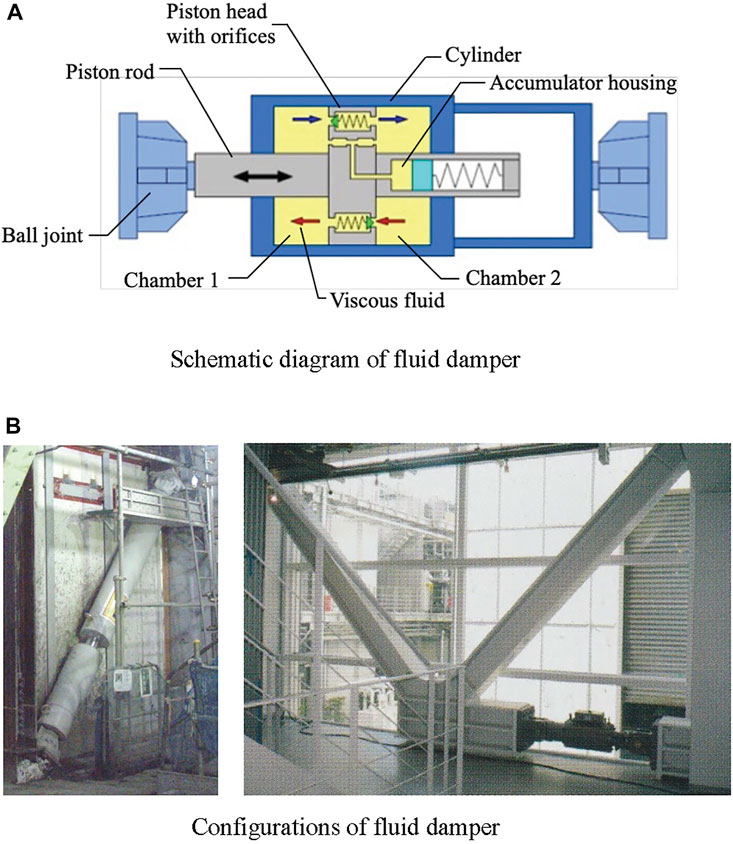
FIGURE 1. Fluid damper for buildings. (A) Schematic diagram of fluid damper. (B) Configurations of fluid damper
A small-size fluid damper was developed based on a general type fluid damper and used mainly for timber frame houses in Japan to reduce earthquake damage, as shown in Figure 2A (Matsuno et al., 1999, 2000). Similar to the general type fluid damper, the small-size fluid damper is installed inter-story, either horizontally (Figure 2A) or diagonally (Figure 2B), and induces a damping force that is proportional to the relative velocity of the piston rod.
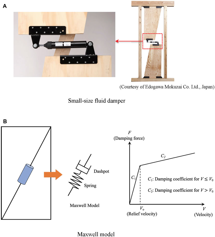
FIGURE 2. Small-size fluid damper for timber frame houses. (A) Small-size fluid damper. (B) Maxwell model.
As shown in Figure 2B, a mechanical model for the small-size fluid damper can be expressed by the Maxwell model that connects a dashpot and a spring in series. The spring represents the stiffness of the connection member or rod. For the dashpot, the relationship between the damping force and the relative velocity is given by a bilinear model (Figure 2B), where the gradient, that is, the damping coefficient, changes when the velocity reaches the relief velocity. The damping force is expressed using the following equation:
where C1 and C2 indicate the initial and second damping coefficients, respectively, V is the relative velocity of the dashpot, and V0 indicates the relief velocity (Matsuno et al., 1999; Manual for Design and Construction of Passively-Controlled Buildings, 3rd Edition, 2013).
The 2016 Kumamoto earthquake occurred beneath Kumamoto City of Kumamoto Prefecture in the Kyushu region, Japan, and was a series of earthquakes: a foreshock earthquake on April 14, and a main earthquake on April 16, 2016. Earthquakes exceeding the JMA Seismic Intensity 7 occurred twice, and the maximum magnitude was 7.3. More than 8,500 houses totally collapsed, and approximately 35,000 houses were partly destroyed, as shown in Figure 3. Even timber frame houses that were designed by the latest quake-proof standards and built after 2000 were destroyed.
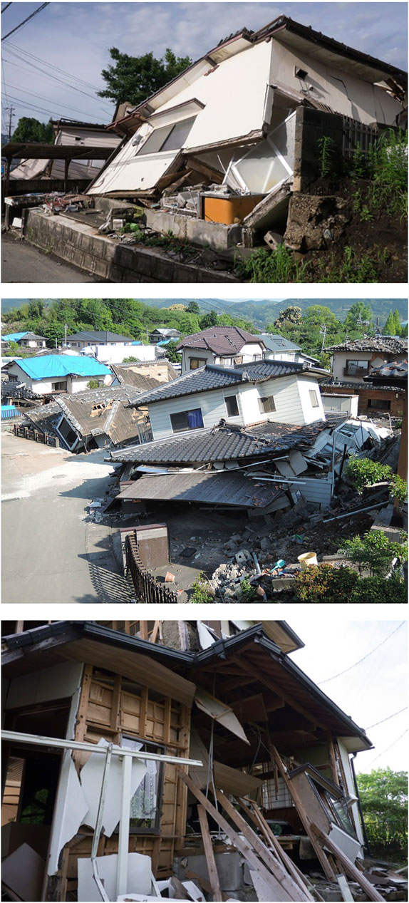
FIGURE 3. Damage of timber frame houses by the 2016 Kumamoto Earthquake.
The records of the foreshock earthquake observed at Mashiki Town in Kumamoto Prefecture, shown in Figure 4A, were used in the response analyses. The displacement response spectra and the acceleration response spectra of the observed records are shown in Figure 4B, C.
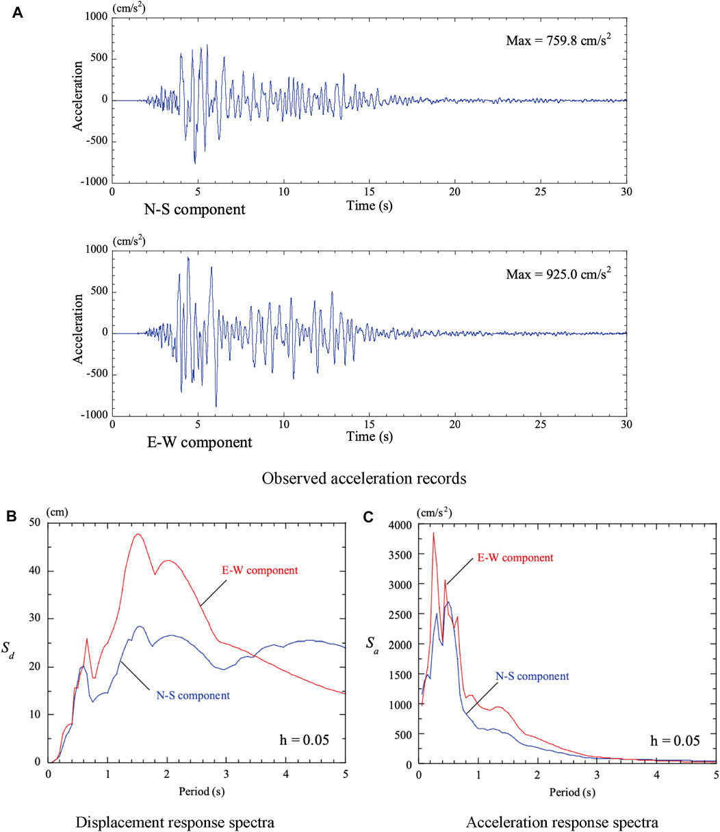
FIGURE 4. Foreshock of the 2016 Kumamoto earthquake (on April 14, 2016). (A) Observed acceleration records. (B) Displacement response records. (C) Acceleration response records.
Timber frame structures are common traditional methods of housing construction in Japan. The seismic performance of timber frame houses can be secured by the load-bearing capacity of erected braces and walls. The lateral resistance of a timber frame house depends on the braces and walls placed in each story. The Japanese design criteria define wall ratio as the load-bearing capacity of a brace or wall, as shown in Figure 5A. One-meter-long wall of wall ratio 1 undergoes a drift angle of 1/120 when subjected to a lateral force of 1.96 kN. Figure 5B shows some specifications of the braces and walls with the granted wall ratios. The necessary wall length, LN (m), per unit floor area (m2) of a two-story timber frame house is provided for each seismic grade, as shown in Figure 5C. The LN for seismic grade 3 is 1.5 times more than that of seismic grade 1. By placing enough braces and walls, the seismic resistance of a timber frame house can be assured by satisfying the following equation in each floor and direction.
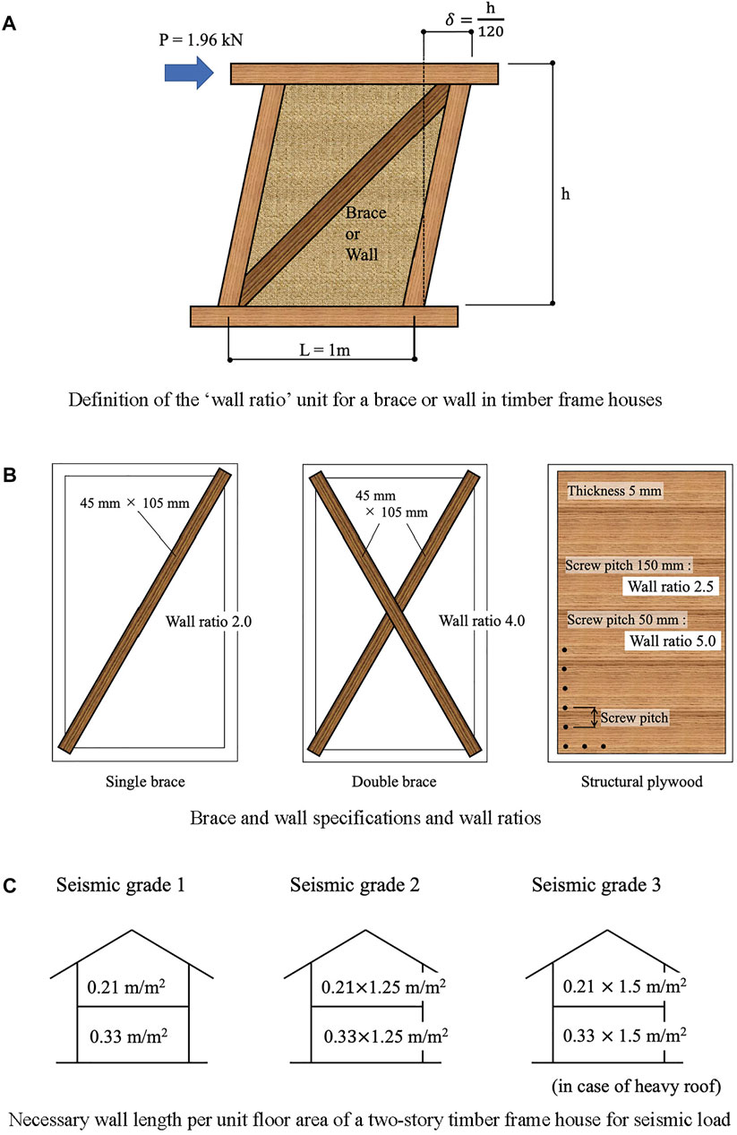
FIGURE 5. Wall ratio and necessary wall length of timber frame houses. (A) Definition of the ‘wall ratio’ unit for a brace or wall in timber frame houses. (B) Brace and wall specifications and wall ratios. (C) Necessary wall length per unit floor area of a two-story timber frame house for seismic load.
Necessary wall length, LN (m), for target seismic grade
where li indicates the length (m) of each brace or wall, n indicates the total number of braces and walls, and ri is the wall ratio.
The framework of the timber frame house used in this study is shown in Figure 6A. The house is an actual two-story timber frame house that was designed and built for seismic grade 3 (the highest grade) using the latest Japanese standards. The columns are made of Japanese cedar and the cross-section size is 12 cm × 12 cm. The beams are made of Douglas fir. The Young’s modulus and the bending yield stress of the columns and beams are 7500 N/mm2 and 24 N/mm2, respectively. The weights of the second story and the rooftop are 246.7 and 127.6 kN, respectively, as shown in Figure 6A.
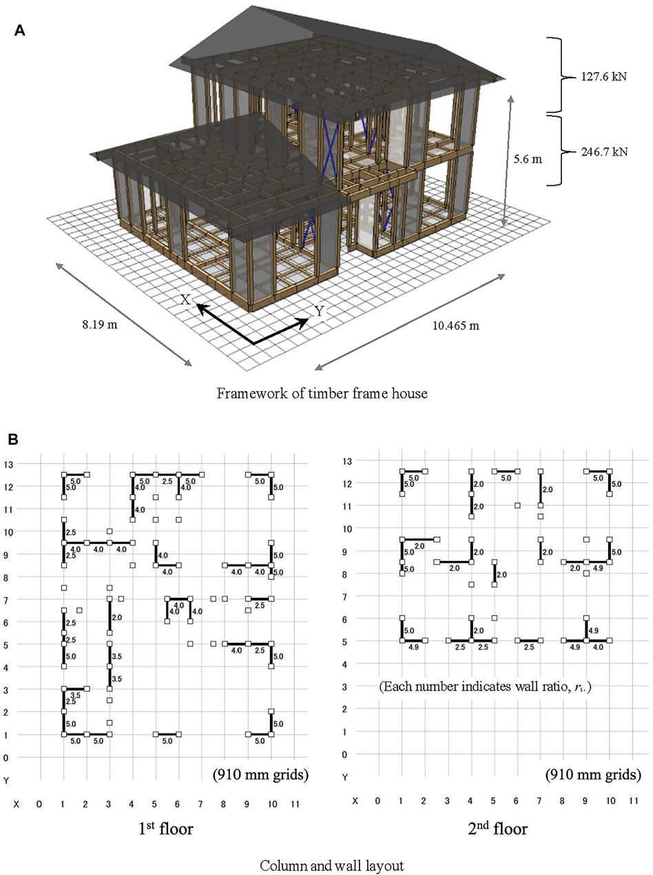
FIGURE 6. Timber frame house for earthquake response analyses. (A) Framework of timber frame house. (B) Column and wall layout.
Figure 6B shows the wall layout and wall ratio of each wall of the timber frame house used in this study. The walls were uniformly placed on each floor. Table 1 shows the existing wall length LE using Eq. 2 and the necessary wall length LN for seismic grade 3 in each floor and direction. Every ratio of LE/LN is greater than one, which proves that the timber frame house secures seismic grade 3.

TABLE 1. Existing and necessary wall lengths and their ratios.
A beam and a column are connected by using a tenon joint or joint metals such as “CP-T” and “Hold-Down (HD)” joints shown in Figure 7A, B shows the joint layout of the timber frame house. In earthquake response analyses in the study, each beam-column joint is expressed by an axial spring and a rotational spring with trilinear elastoplastic properties shown in Figure 8A, B. Every timber beam or column is converted into an elastic bar element with rotational springs at both ends shown in Figure 8A, C.
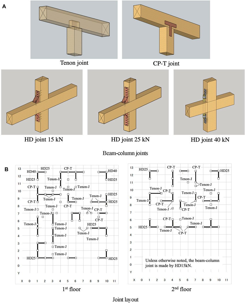
FIGURE 7. Joints of timber frame house. (A) Beam-column joints. (B) Joint layout.
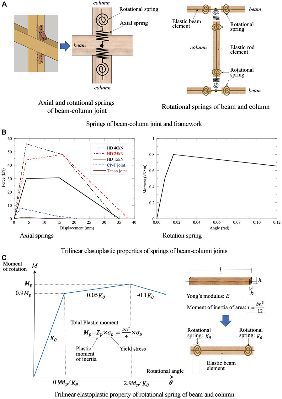
FIGURE 8. Analytical models of joints and framework. (A) Springs of beam-column joint and framework. (B) Trilinear elastoplastic properties of springs of beam-column joints. (C) Trilinear elastoplastic property of rotational spring of beam and column.
As shown in Figure 9, small-size fluid dampers are placed at locations #1 to #7 on the first floor in the X-direction, because in the preliminary response analyses the inter-story drifts of the first story in the X-direction were dominant and the house model broke down in the X-direction (as shown later in Figure 10A, 11A). In this study, a small-size fluid damper is installed diagonally in a brace configuration and acquires the properties given in Figure 9. The properties of the damper were based on the performance tests of the manufactured small-size damper. The target maximum story drift angle is specified as 1/30 because a timber frame house is most likely to be severely damaged or broke down when the story angle exceeds 1/30. Considering the wall layout (Figure 6B) and the realistic installation cost, the number of dampers is limited to seven. The following three cases of placing dampers in the first story in the X-direction are considered in this study:
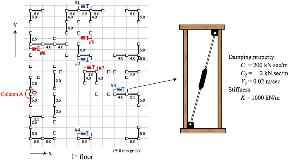
FIGURE 9. Layout of small-size fluid dampers in first floor.
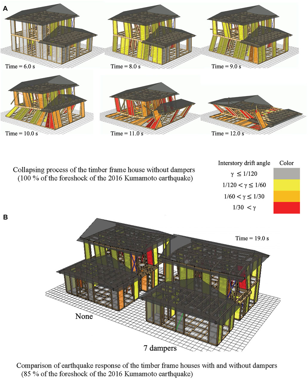
FIGURE 10. 3D pictures of earthquake response analyses of the timber frame house. (A) Collapsing process of the timber frame house without dampers(100 % of the foreshock of the 2016 Kumamoto earthquake). (B) Comparison of earthquake response of the timber frame houses with and without dampers.
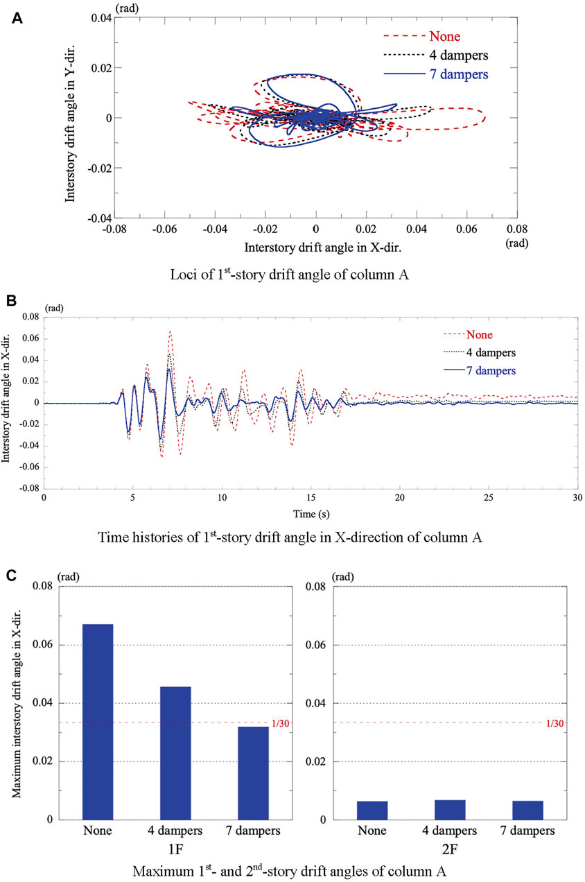
FIGURE 11. Results of earthquake response analyses of the timber house with and without dampers. (A) Loci of 1st-story drift angle of column A. (B) Time histories of 1st-story drift angle in X-direction of column A. (C) Maximum 1st- and 2nd-story drift angles of column A.
None: No damper is installed, i.e., the original timber frame house.
Four dampers: Four dampers are installed at locations #1 to #4 in the first story in the X-direction.
Seven dampers: Seven dampers are installed at locations #1 to #7 in the first story in the X-direction.
In this study, a collapse analysis program for timber structures “wallstat” is used for earthquake response analyses. The “wallstat” program was developed by Prof. Takafumi Nakagawa of Kyoto University to assess the damage status and the likelihood of collapse of a timber structure when subjected to an earthquake motion (Nakagawa and Ohta, 2010; Suzuki and Nakagawa, 2020). The program utilizes the distinct element method, which is a non-continuum analysis method and is applicable to large deformation and collapse analysis.
The “wallstat” program can analyze a timber frame house model installed with fluid dampers or elastoplastic dampers. A fluid damper is expressed by either the Maxwell model that connects a dashpot and a spring in series or the Voigt model that connects a dashpot and a spring in parallel. An elastoplastic damper is represented by a bilinear model. In this study, the Maxwell model was used for the installed small-size fluid damper, as mentioned in Small-Size Fluid Damper.
The validity of the “wallstat” program was verified through the comparison between the simulation results and the shaking table tests of full-size housing models (Nakagawa et al., 2006, 2007; Fukumoto et al., 2008). Destructive damage of timber frame houses by the 2016 Kumamoto Earthquake was analyzed by the “wallstat” program (Nakagawa, 2017; Namba et al., 2020). The program is a free software that researchers and engineers can download from the website with the manual, and is now widely used by housing makers to demonstrate the earthquake-proofing performance of timber frame houses in high seismic grades.
Figure 10A shows the collapsing process of the house model without dampers when subjected to 100% of the foreshock of the 2016 Kumamoto Earthquake. Similarly, the house model installed with seven dampers (Figure 9) broke down under the same input. The results demonstrate that the foreshock (Figure 4) was quite severe for two-story timber frame houses. In this study, 85% of the foreshock records were used for the earthquake response analyses: the N-S component in the X-direction and the E-W component in the Y-direction.
Figure 10B shows a comparison of earthquake responses between the house model without dampers and that installed with seven dampers after being subjected to 85% of the foreshock records. Figure 11A, B show the loci and time-histories in the X-direction, respectively, for the first-story drift angle of column A for the three cases: none, four dampers, and seven dampers. Figure 11C shows the maximum values of the first- and second-story drift angle of column A for each case. For the model without dampers, the first-story drift angle reached 1/15, and the structure was on the verge of collapse.
These results indicate that the installed fluid dampers are effective in reducing the first-story drift angle but have no effect on the second-story drift angle. The maximum first-story drift angle is reduced from 1/15 to 1/22 (approximately 70%) owing to the four dampers, and from 1/15 to 1/31 (approximately 50%) owing to the seven dampers. In addition, the dampers have a favorable effect on suppressing residual deformation, as shown in Figure 11B.
Figure 11B also shows that the fundamental period of the house model in the X-direction was approximately 0.6 s for small amplitudes and became longer for large oscillations owing to the elastoplastic properties of the beam-column joint. In the case of the model without dampers, the fundamental period nearly doubled when the first-story drift angle was at its maximum. The installed dampers controlled the elongation of the fundamental period and restrained the amplitude growth.
Figure 12A shows the maximum values of the first- and second-story drift angle of column A of the house model subjected to the three major earthquakes in the X-direction; El Centro 1940 (NS), Taft 1952 (EW), and Hachinohe 1968 (NS) whose peak velocity is normalized to 50 cm/s. The maximum story drift angles are much less than those of the house subjected to 85% of the foreshock of the 2016 Kumamoto Earthquake. As for El Centro 1940 (NS) input, the maximum first-story drift angle is reduced from 1/38 to 1/52 (approximately 73%) owing to the four dampers, and from 1/38 to 1/70 (approximately 54%) owing to the seven dampers.
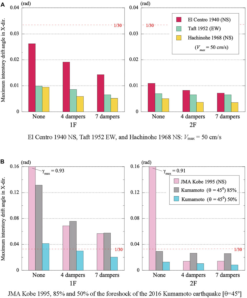
FIGURE 12. Maximum 1st- and 2nd-story drift angles of column A of the timber house. with and without dampers. (A) El Centro 1940 NS, Taft 1952 EW, and Hachinohe 1968 NS: Vmax = 50 cm/s. (B) JMA Kobe 1995, 85% and 50% of the foreshock of the 2016 Kumamoto earthquake [θ=45o].
Figure 12B shows the maximum values of the first- and second-story drift angle of column A of the house subjected to JMA Kobe 1995 (NS) in the X-direction, and to the 85 and 50% of the foreshock of the 2016 Kumamoto Earthquake at an angle of attack of 45°. As for JMA Kobe (NS) and 85% of Kumamoto input, the house model without dampers broke down, and the dampers can reduce the first-story drift angle effectively, but even the seven dampers cannot prevent serious damage.
Figure 13 shows the maximum acceleration values of the second floor and the rooftop of the house subjected to the 85% of the foreshock of the 2016 Kumamoto Earthquake and to the three major earthquakes whose peak velocity is normalized to 50 cm/s. These results indicate that the dampers have no effect in reducing the response acceleration. It may be because the fundamental period of the house model with dampers remains shorter and the damping effect is relatively small.
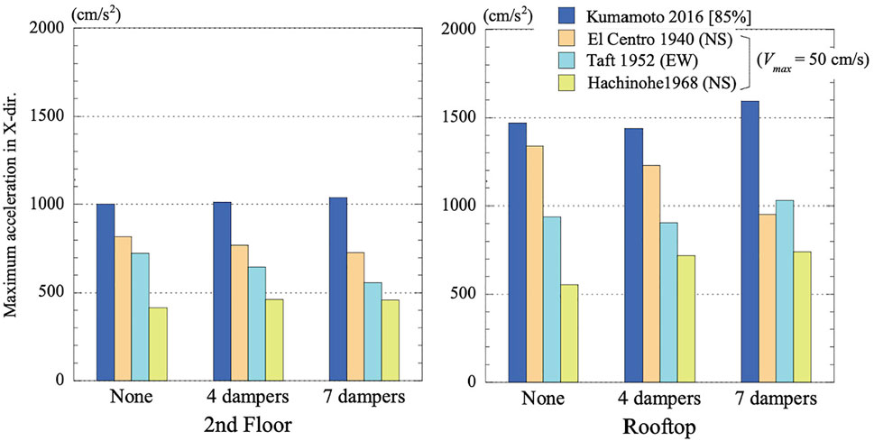
FIGURE 13. Maximum 2nd-floor and rooftop acceleration of the timber frame house.
The Japanese design method for timber frame houses (in Design Criteria for Timber Frame Houses in Japan) considers the braces and walls as the load-bearing members against earthquakes, and takes no account of the damping property of dampers. Only the stiffness or load-bearing capacity of dampers can be taken into account as structural braces or walls. Some dampers using viscoelastic material or high-damping rubber obtain a certificate of wall ratio as a structural member. The small-size fluid damper does not own stiffness property, but the equivalent wall ratio can be estimated in terms of the maximum earthquake response.
To estimate the equivalent wall ratio of a small-size fluid damper, a series of comparative response analyses were carried out between a small-size fluid damper and a conventional structural wall. Figure 14A shows the layout of the four fluid dampers and the counterpart of four additional structural walls with a specified wall ratio, r. The maximum values of the first-story drift angle of column A were obtained from earthquake response analyses of the model installed with four additional structural walls by varying its wall ratio, r, from 1 to 5. Figure 14B shows the maximum first-story drift angles for the five cases with four additional structural walls and that for the case of four dampers. The results imply that a small-size fluid damper in the study has an equivalent quake resistance to a conventional structural wall of r = 3 plus.
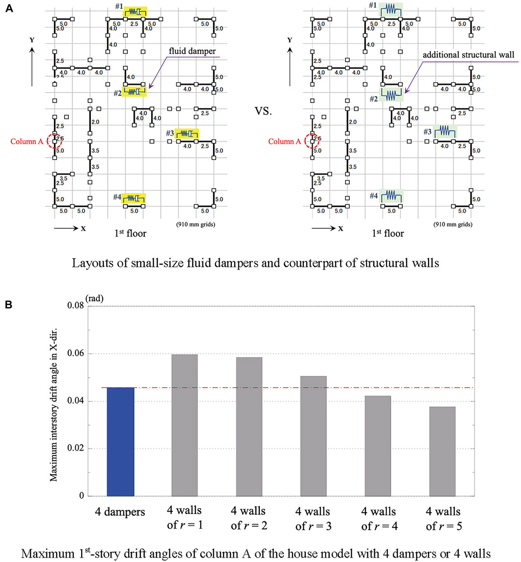
FIGURE 14. Comparative response analyses between small-size fluid dampers and conventional structural walls. (A) Layouts of small-size fluid dampers and counterpart of structural walls. (B) Maximum 1st-story drift angles of column A of the house model with 4 dampers or 4 walls.
In this study, the effectiveness of a small-size fluid damper in reducing oscillations was investigated by earthquake response analyses of a two-story timber frame house subjected to 85% of the foreshock records of the 2016 Kumamoto earthquake and other major earthquakes. The analytical model was based on an actual two-story timber frame house that was designed based on the latest Japanese standards for the highest seismic grade. The small-size fluid damper in this study was developed for timber frame houses based on a general type of fluid damper, and was installed diagonally in a brace configuration in the first story in the X-direction of the model. The mechanical model for the small-size fluid damper is expressed by the Maxwell model whose dashpot induces a damping force that is proportional to the relative velocity. A collapse analysis program for timber structures “wallstat” was used for earthquake response analyses.
The followings are the main conclusions of the study of the house model subjected to 85% of the foreshock records of the 2016 Kumamoto earthquake:
1) For the house model without dampers, the first-story drift angle reached 1/15, and the structure was on the verge of collapse. The fundamental period in the X-direction was approximately 0.6 s for small amplitudes and nearly doubled when the first-story drift angle was at its maximum.
2) The small-size fluid dampers in the first story are effective in reducing the first-story drift angle but have no effect on the second-story drift angle. As for The maximum first-story drift angle is reduced from 1/15 to 1/22 (approximately 70%) owing to the four dampers, and from 1/15 to 1/31 (approximately 50%) owing to the seven dampers.
3) The small-size fluid dampers have a favorable effect on suppressing the residual deformation. They controlled the elongation of the fundamental period during the response and restrained the amplitude growth, but have no effect in reducing the response acceleration.
4) In the light of maximum interstory drifts during an earthquake, a small-size fluid damper in the study has an equivalent quake resistance to a structural wall with a wall ratio of 3 plus.
Earthquake response analyses of a timber frame house model in the study demonstrated that the small-size fluid damper can prevent extensive damage and collapse up to 85% of the observed foreshock records of the 2016 Kumamoto earthquake, and reduce the first-story drift according to the number of installed dampers. The damper owns an equal effect on the other major earthquakes.
The small-size fluid damper can be installed inter-story, either horizontally or diagonally, together with a conventional structural wall. Another merit is that the damper can be applied to an existing house as a seismic retrofitting measure. The cost of installation of the damper is a little higher than that of the conventional structural walls, but should be acceptable considering the effects in reducing oscillations. The damper is useable for 60 years in the maintenance-free condition. There is room for further research for applications of the small-size fluid damper to low-rise structures made of laminated wood members. The results of this study can help further the applications of small-size fluid dampers.
The original contributions presented in the study are included in the article/Supplementary Material, further inquiries can be directed to the corresponding author.
YN: modeling of the timber frame house and the small-size fluid damper. HF: time-history response analyses of the timber frame house model.
This study was supported by the JSPS KAKENHI (Grant Number JP20K04792).
The authors declare that the research was conducted in the absence of any commercial or financial relationships that could be construed as a potential conflict of interest.
All claims expressed in this article are solely those of the authors and do not necessarily represent those of their affiliated organizations, or those of the publisher, the editors and the reviewers. Any product that may be evaluated in this article, or claim that may be made by its manufacturer, is not guaranteed or endorsed by the publisher.
The authors would like to express their appreciation to Prof. Takafumi Nakagawa of Kyoto University for his advice on the use of wallstat, to Kohji Asakawa for permission to use the pictures of the 2016 Kumamoto earthquake, to Ichijo Co. Ltd. for providing the design documents of the timber frame house and to Edogawa Mokuzai Co. Ltd. for permission to use the pictures of the small-size fluid damper.
Constantinou, M. C., and Symans, M. D. (1992). Experimental and Analytical Investigation of Seismic Response of Structures with Supplemental Fluid Viscous Dampers. Technical Report NCEER-92-0032. Buffalo, NY: National Center for Earthquake Engineering Research.
Constantinou, M. C., and Symans, M. D. (1993). Experimental Study of Seismic Response of Buildings with Supplemental Fluid Dampers. Struct. Des. Tall Build. 2 (2), 93–132. doi:10.1002/tal.4320020203
De Domenico, D., and Hajirasouliha, I. (2021). Multi-level Performance-Based Design Optimisation of Steel Frames with Nonlinear Viscous Dampers. Bull. Earthquake Eng. 19, 5015–5049. doi:10.1007/s10518-021-01152-7
De Domenico, D., and Ricciardi, G. (2019). Earthquake protection of Structures with Nonlinear Viscous Dampers Optimized through an Energy-Based Stochastic Approach. Eng. Structures 179, 523–539. doi:10.1016/j.engstruct.2018.09.076
De Domenico, D., Ricciardi, G., and Takewaki, I. (2019). Design Strategies of Viscous Dampers for Seismic protection of Building Structures: A Review. Soil Dyn. Earthquake Eng. 118, 144–165. doi:10.1016/j.soildyn.2018.12.024
Design of Seismic Isolation and Response Control. (2016). Kanto Branch of the Architectural Institute of Japan. (in Japanese)
Dong, B., Sause, R., and Ricles, J. M. (2016). Seismic Response and Performance of a Steel MRF Building with Nonlinear Viscous Dampers under DBE and MCE. J. Struct. Eng. 142, 6. doi:10.1061/(asce)st.1943-541x.0001482
Fu, Y., and Kasai, K. (1998). Comparative Study of Frames Using Viscoelastic and Viscous Dampers. J. Struct. Eng. 124 (5), 513–522. doi:10.1061/(asce)0733-9445(1998)124:5(513)
Fukumoto, Y., Koshihara, M., Miyake, T., Nakagawa, T., and Tsuchimoto, T. (2008). “Verification for Seismic Performance of Existing wood Houses by Shaking Table Test (Part 29: Response Analysis of 2-DOF System for the Test),” in Summaries of technical papers of annual meeting (Tokyo, Japan: Architectural Institute of Japan), 137–138. (in Japanese).
Hao, L., and Zhang, R. (2016). Structural Safety Redundancy-Based Design Method for Structure with Viscous Dampers. Struct. Eng. Mech. 59 (5), 821–840. doi:10.12989/sem.2016.59.5.821
Hwang, J.-S., Huang, Y.-N., Yi, S.-L., and Ho, S.-Y. (2008). Design Formulations for Supplemental Viscous Dampers to Building Structures. J. Struct. Eng. 134 (1), 22–31. doi:10.1061/(asce)0733-9445(2008)134:1(22)
Idels, O., and Lavan, O. (2020). Optimization‐based Seismic Design of Steel Moment‐resisting Frames with Nonlinear Viscous Dampers. Struct. Control. Health Monit. 28, 1e2655. doi:10.1002/stc.2655
Impollonia, N., and Palmeri, A. (2018). Seismic Performance of Buildings Retrofitted with Nonlinear Viscous Dampers and Adjacent Reaction Towers. Earthquake Engng Struct. Dyn. 47 (5), 1329–1351. doi:10.1002/eqe.3020
Kasai, K., Nakai, M., Nakai, M., Nakamura, Y., Asai, H., Suzuki, Y., et al. (2009). Building Passive Control in Japan. J. Disaster Res. 4 (3), 261–269. doi:10.20965/jdr.2009.p0261
Kasai, K., Nakai, M., Nakamura, Y., Asai, H., Suzuki, Y., and Ishii, M. (2008). “Current Status of Building Passive Control in Japan,”. October 12-17 in Proceedings of the 14th World Congress on Earthquake Engineering (Beijing, China.
Kawamoto, T., Fujita, K., Tsuji, M., and Takewaki, I. (2016). Robust Optimal Placement of Dampers in Structures with Set-Back and Eccentricity Using Sensitivity Analysis for Integrated Transfer Function. Ijeie 1 (4), 377–394. doi:10.1504/IJEIE.2016.083252
Lavan, O., and Levy, R. (2005). Optimal Design of Supplemental Viscous Dampers for Irregular Shear-Frames in the Presence of Yielding. Earthquake Engng Struct. Dyn. 34 (8), 889–907. doi:10.1002/eqe.458
Lavan, O., and Levy, R. (2006). Optimal Design of Supplemental Viscous Dampers for Linear Framed Structures. Earthquake Engng Struct. Dyn. 35 (3), 337–356. doi:10.1002/eqe.524
Lavan, O. (2015). Optimal Design of Viscous Dampers and Their Supporting Members for the Seismic Retrofitting of 3D Irregular Frame Structures. J. Struct. Eng. 141, 04015026. 11. doi:10.1061/(ASCE)ST.1943-541X.0001261
Lee, D., and Taylor, D. P. (2001). Viscous Damper Development and Future Trends. Struct. Des. Tall Build. 10 (5), 311–320. doi:10.1002/tal.188
Liang, Z., Lee, G. C., Dargush, G. F., and Song, J. (2012). Structural Damping: Application in Seismic Response Modification. FL: CRC Press, Taylor & Francis Group.
Lin, W. H., and Chopra, A. K. (2002). Earthquake Response of Elastic SDF Systems with Non-linear Fluid Viscous Dampers. Earthquake Eng. Struct. Dyn. 31 (9), 623–642. doi:10.1002/eqe.179
Manual for Design and Construction of Passively-Controlled Buildings, 3rd Edition (2013). The Japan Society of Seismic Isolation. (in Japanese).
Martinez-Rodrigo, M., and Romero, M. L. (2003). An Optimum Retrofit Strategy for Moment Resisting Frames with Nonlinear Viscous Dampers for Seismic Applications. Eng. Structures 25 (7), 913–925. doi:10.1016/s0141-0296(03)00025-7
Matsuno, A., Hashimoto, J., Katayama, Y., and Fukui, K. (1999). “Application of the Oil Damper to Wooden House by Conventional Construction Method (Part 1: Verification of Damping Effect by experiment and Simulation),” in Summaries of technical papers of annual meeting (Tokyo, Japan: Architectural Institute of Japan), 179–180. (in Japanese).
Matsuno, A., Hashimoto, J., and Katayama, Y. (2000). Vibration Test of Wooden House with Oil Damper.Summaries Of Technical Papers of Annual Meeting. (Tokyo, Japan: Architectural Institute of Japan), 1113–1114. (in Japanese).
McNamara, R. J., and Taylor, D. P. (2003). Fluid Viscous Dampers for High-Rise Buildings. Struct. Des. Tall Spec. Build. 12 (2), 145–154. doi:10.1002/tal.218
Nakagawa, T., Kawai, N., Tsuchimoto, T., and Ohta, M. (2007). “Verification for Seismic Performance of Existing wood Houses by Shaking Table Test (Part 26: Collapsing Process Simulations by the Extended Distinct Element Method),” in Summaries of technical papers of annual meeting (Tokyo, Japan: Architectural Institute of Japan), 489–490. (in Japanese).
Nakagawa, T., Kawai, N., Tsuchimoto, T., and Okabe, M. (2006). “Verification for Seismic Performance of Existing wood Houses by Shaking Table Test (Part 15: Structural Performance of Wooden Frame walls in the Building by Shaking Table Tests),” in Summaries of technical papers of annual meeting (Tokyo, Japan: Architectural Institute of Japan), 395–396. (in Japanese).
Nakagawa, T., Ohta, M., Tsuchimoto, T., and Kawai, N. (2010). Collapsing Process Simulations of Timber Structures under Dynamic Loading III: Numerical Simulations of Real-Size Wooden Houses. J. Wood Sci. 56 (4), 284–292. doi:10.1007/s10086-009-1101-x
Nakagawa, T. (2017). “Seismic Response Analysis of Wooden Houses Using Ground Motion Observed at 2016 Kumamoto Earthquakes,” in Summaries of technical papers of annual meeting (Tokyo, Japan: Architectural Institute of Japan), 489–490. (in Japanese).
Namba, T., Sumida, K., Nakagawa, T., and Isoda, H. (2020). Seismic Response Analysis of a Collapsed Wooden House in 2016 Kumamoto Earthquake.Summaries of Technical Papers of Annual Meeting. Architectural Institute of Japan, 433–434. (in Japanese).
Parcianello, E., Chisari, C., and Amadio, C. (2017). Optimal Design of Nonlinear Viscous Dampers for Frame Structures. Soil Dyn. Earthquake Eng. 100, 257–260. doi:10.1016/j.soildyn.2017.06.006
Pollini, N., Lavan, O., and Amir, O. (2017). Minimum-cost Optimization of Nonlinear Fluid Viscous Dampers and Their Supporting Members for Seismic Retrofitting. Earthquake Eng. Struct. Dyn. 46 (12), 1941–1961. doi:10.1002/eqe.2888
Pollini, N., Lavan, O., and Amir, O. (2016). Towards Realistic Minimum-Cost Optimization of Viscous Fluid Dampers for Seismic Retrofitting. Bull. Earthquake Eng. 14 (3), 971–998. doi:10.1007/s10518-015-9844-9
Rama Raju, K., Ansu, M., and Iyer, N. R. (2014). A Methodology of Design for Seismic Performance Enhancement of Buildings Using Viscous Fluid Dampers. Struct. Control. Health Monit. 21 (3), 342–355. doi:10.1002/stc.1568
Seleemah, A. A., and Constantinou, M. C. (1997). Technical Report NCEER-97-0004. Buffalo, NY: National Center for Earthquake Engineering Research. Investigation of Seismic Response of Buildings with Linear and Nonlinear Fluid Viscous Dampers
Seo, C.-Y., Karavasilis, T. L., Ricles, J. M., and Sause, R. (2014). Seismic Performance and Probabilistic Collapse Resistance Assessment of Steel Moment Resisting Frames with Fluid Viscous Dampers. Earthquake Engng Struct. Dyn. 43 (14), 2135–2154. doi:10.1002/eqe.2440
Silvestri, S., and Trombetti, T. (2007). Physical and Numerical Approaches for the Optimal Insertion of Seismic Viscous Dampers in Shear-type Structures. J. Earthquake Eng. 11 (5), 787–828. doi:10.1080/13632460601034155
Soong, T. T., and Dargush, G. F. (1997). Passive Energy Dissipation Systems in Structural Engineering. Chichester: John Wiley & Sons.
Soong, T. T., and Spencer, B. F. (2002). Supplemental Energy Dissipation: State-Of-The-Art and State-Of-The-Practice. Eng. Structures 24 (3), 243–259. doi:10.1016/s0141-0296(01)00092-x
Sorace, S., and Terenzi, G. (2008). Seismic protection of Frame Structures by Fluid Viscous Damped Braces. J. Struct. Eng. 134 (1), 45–55. doi:10.1061/(asce)0733-9445(2008)134:1(45)
Sorace, S., Terenzi, G., and Terenzi, G. (2009). Fluid Viscous Damper-Based Seismic Retrofit Strategies of Steel Structures: General Concepts and Design Applications. Adv. Steel Construction 5 (3), 325–342. doi:10.18057/ijasc.2009.5.3.7
Suzuki, T., and Nakagawa, T. (2020). Seismic Simulation Wallstat Guide. Japan: Gakugei Shuppan Publishing Co. Ltd. (in Japanese).
Tabar, A. M., De Domenico, D., and Dindari, H. (2021). Seismic Rehabilitation of Steel Arch Bridges Using Nonlinear Viscous Dampers: Application to a Case Study. Pract. Periodical Struct. Des. Construction 26 (3), 04021012. doi:10.1061/(ASCE)SC.1943-5576.0000576
Takewaki, I. (2009). Building Control with Passive Dampers: Optimal Performance-Based Design for Earthquakes. Singapore: John Wiley & Sons (Asia) Pte Ltd.
Taylor, D. P., and Constantinou, M. C. (1995). Testing Procedures for High Output Fluid Viscous Dampers Used in Building and Bridge Structures to Dissipate Seismic Energy. J. Shock Vibration 2 (5), 378–381. doi:10.1155/1995/676035
Tsuji, M., and Nakamura, T. (1996). Optimum Viscous Dampers for Stiffness Design of Shear Buildings. Struct. Des. Tall Build. 5 (3), 217–234. doi:10.1002/(sici)1099-1794(199609)5:3<217:aid-tal70>3.0.co;2-r
Tubaldi, E., Barbato, M., and Dall’Asta, A. (2014). Performance-based Seismic Risk Assessment for Buildings Equipped with Linear and Nonlinear Viscous Dampers. Eng. Structures 78, 90–99. doi:10.1016/j.engstruct.2014.04.052
Uetani, K., Tsuji, M., and Takewaki, I. (2003). Application of an Optimum Design Method to Practical Building Frames with Viscous Dampers and Hysteretic Dampers. Eng. Structures 25, 579–592. doi:10.1016/S0141-0296(02)00168-2
Uriz, P., and Whittaker, A. S. (2001). Retrofit of Pre-Northridge Steel Moment-Resisting Frames Using Fluid Viscous Dampers. Struct. Des. Tall Build. 10 (5), 371–390. doi:10.1002/tal.199
Wang, S., and Mahin, S. A. (2018). High-performance Computer-Aided Optimization of Viscous Dampers for Improving the Seismic Performance of a Tall Building. Soil Dyn. Earthquake Eng. 113, 454–461. doi:10.1016/j.soildyn.2018.06.008
Keywords: earthquake damage, timber frame house, fluid damper, response analysis, the 2016 Kumamoto earthquake, inter-story drift, wall ratio
Citation: Nakamura Y and Fujii H (2021) Earthquake Damage Reduction in Timber Frame Houses Using Small-Size Fluid Damper. Front. Built Environ. 7:767741. doi: 10.3389/fbuil.2021.767741
Received: 31 August 2021; Accepted: 03 November 2021;
Published: 25 November 2021.
Edited by:
Shehata E. Abdel Raheem, Assiut University, EgyptReviewed by:
Giuseppe Ricciardi, University of Messina, ItalyCopyright © 2021 Nakamura and Fujii. This is an open-access article distributed under the terms of the Creative Commons Attribution License (CC BY). The use, distribution or reproduction in other forums is permitted, provided the original author(s) and the copyright owner(s) are credited and that the original publication in this journal is cited, in accordance with accepted academic practice. No use, distribution or reproduction is permitted which does not comply with these terms.
*Correspondence: Yutaka Nakamura, eXV0YWthLm5ha2FtdXJhQHJpa28uc2hpbWFuZS11LmFjLmpw
Disclaimer: All claims expressed in this article are solely those of the authors and do not necessarily represent those of their affiliated organizations, or those of the publisher, the editors and the reviewers. Any product that may be evaluated in this article or claim that may be made by its manufacturer is not guaranteed or endorsed by the publisher.
Research integrity at Frontiers
Learn more about the work of our research integrity team to safeguard the quality of each article we publish.