- 1Department of European and Mediterranean Cultures (Architecture, Environment and Cultural Heritage), University of Basilicata, Matera, Italy
- 2Department of Structural and Geotechnical Engineering, Sapienza University of Rome, Rome, Italy
Nowadays, seismic retrofit through isolation strategy represents a consolidated technique of protection against design earthquakes. This technique is also applied on existing structures extensively, due to the fact that it usually does not require any interruption of the building use and occupants evacuation. If applicable, it rapidly allows the seismically retrofitting of a building installed with seismic devices with low horizontal stiffness between the structure and the foundation decoupling, in fact, this allows the motion of the superstructure from the ground one. In this paper an application on an existing RC building of the seismic isolation is presented. The chosen building was built in the ‘90s only for vertical loads and realized without any detailing rule for structural ductility. The seismic retrofitting requirement stems from the fact that only recently, after the National seismic hazard maps update in 2003, the considered area has been upgraded to a medium-low seismic intensity zone, while at construction time no seismic classification was in existence by law. The case study peculiarity is that the seismic retrofitting has required an addition to seismic devices at the base, with related interventions such as the application of a bracing system consisting of two elastic steel frames. This intervention is required for stiffening the superstructure and, therefore, minimizing the higher vibration modes effects. The paper presents the main results obtained with a FEM model, implemented for simulating the initial and the design state when the interventions are considered. Finally, some results of non-linear dynamic time-history analyses are illustrated and commented for verifying superstructure elements and seismic devices.
Introduction
Seismic isolation is actually a design strategy largely applied all over the world either for designing new buildings or for retrofitting existing ones. Essentially, it consists in decoupling the superstructure motion from the ground one by installing seismic devices having a low horizontal stiffness. The result of lengthening the superstructures fundamental natural period, significantly reduces the seismic demand in terms of lateral accelerations, with a consequent increase of lateral displacements. In this way the superstructure elements damage may be nullified thanks to the drastic reduction of the interstory drifts and floor shear (Kelly, 1986; Alhan and Gavin, 2004; Ibrahim, 2008). Therefore, the seismic isolation strategy, if applicable, results particularly convenient with respect to the classical one of locally strengthening the structural elements. In this case, in fact, the elements strength is being increased instead of reducing the seismic action, through local interventions also suggested by the observation of the typical response mechanisms occurred in the last seismic events (De Matteis et al., 2005; Formisano et al., 2006, 2016; D'Amato et al., 2017; Laterza et al., 2017a,b; Morelli et al., 2017; Caprili et al., 2018; Fuentes et al., 2019a,b; Ramírez et al., 2019). Seismic isolation may result convenient if compared with the design strategy considering dissipative bracing systems, where an increase of stiffness and strength through additional elements is provided to the structure (Ciampi et al., 1995; Mazza and Vulcano, 2014; Formisano et al., 2016, 2017; Laguardia et al., 2017; Braga et al., 2019; Panzera et al., 2020).
As known, the dynamic response of an isolated building strictly depends on the characteristics of the isolation devices and having the combined function of building re-centering during the horizontal oscillations and dissipating the kinetic energy. Different typologies of the isolation devices may be applied and combined among them such as elastomeric devices, flat sliders, friction pendulum devices, elasto-plastic dissipators. In literature, general studies and applications with these devices for isolation buildings may be found in Braga et al. (2005), Constantinou et al. (1990), Martelli and Forni (1998), Mokha et al. (1988), Kawamura et al. (2000) and Kelly (2002), and specific applications on existing buildings having also historic value may be found in De Luca et al. (2001), Mokha et al. (1996), Tomazevic et al. (2009), Castellano et al. (2014), Petrovčič and Kilar (2017) and D'Amato et al. (2019). Recently, studies have also addressed to assess the actual properties of elastomeric devices through the nanoindentation technique avoiding, therefore, removing devices for laboratory testing. To this scope an innovative procedure has been proposed in Rossi et al. (2020).
This paper illustrates the application of the seismic isolation at the base as structural retrofitting, to an existing Reinforced Concrete (RC) building located in Marconia, in southern Italy. The building was designed only for vertical loads and built without any detailing rule for structural ductility and due to the date and time of the construction of the building, the building site fell within an area not classified as seismic. After the National seismic hazard maps update in 2003, the seismic classification of the area of the building has been under consideration and has been upgraded, and classified as a medium-low seismic intensity zone. The case study results are interesting since the application of the seismic isolation has also required the realization, only along the building transverse direction, and an additional bracing system throughout the height consisting of two lateral elastic steel frames. This intervention has been necessary in order to stiff the superstructure and to reduce high vibration mode effects as much as possible.
The paper presents the main results related to numerical simulations through implementation of FEM models, considering the “as-built” initial condition with a Fixed-Based (FB) model, and the retrofitted configuration with a Seismic Isolated (SI) model. All the investigations, numerical analyses, and verifications shown in this study are conducted by referring to the Italian design code (NTC, 2008), that is the design code adopted for retrofitting the case study. It should be underlined, however, that no significant modification has been introduced with the next design code update (NTC, 2018) as far as what is concerned in this study. Moreover, due to their current characteristics all masonry infills (perimetral and internal partitions made by simple hollowed brick blocks) are assumed as non-structural elements. They, as indicated by many seismic design codes including the NTC (2008), are modeled only in terms of vertical loads with the related masses, since they do not significantly affect the lateral response in terms of stiffness and strength.
Firstly, the paper discusses of the main structural deficiencies encountered by considering the seismic action, and describes the isolation system design with the related interventions. Then, results of numerical investigations are shown by evaluating the influence of the bracing system on the superstructure response. Finally, some results of the non-linear time-history analyses are illustrated for verifying the design displacement of the seismic devices.
Case Study Description
The chosen case study is a RC building designed in the ‘90s and built in Marconia, a locality of the Pisticci Municipality (Province of Matera, Italy). It was realized by ATER, which is the local company for housing of the Basilicata Region, with the aim of providing social housing to the applicants.
The building is composed by seven floors plus a two-pitch roofing system. The pilotis ground floor is used as porch, while the upper six floors are used for housing. Some image of the considered building in the “as-built” condition is reported in Figures 1A,B. While a foundation plan and a transverse section are illustrated in Figures 1C,D, respectively. In plan the building is a simple rectangle of dimensions 20.10 × 11.0 m, reaching the maximum height measured above the ahead foundation of 21.1 m. The foundations were realized through inverted T beams strips having a total height of 1.50 m and a width of 0.50 m (the flange has dimensions 1.60 × 0.50 m). The ground floor has an height of 3.1 m, and was realized with an incoherent foundation back-fill within. The other floors have a constant height of 3.0 m.
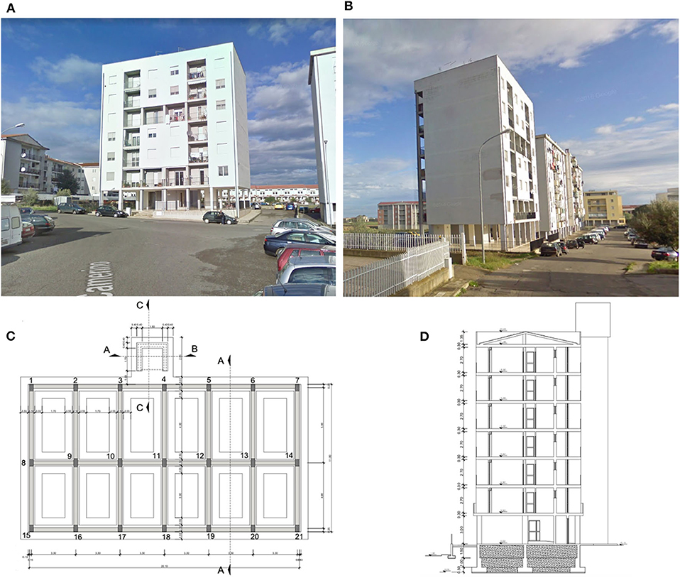
Figure 1. (A,B) Prospective views of the case study, (C) foundation beams plan and (D) transverse section in the “as built” condition.
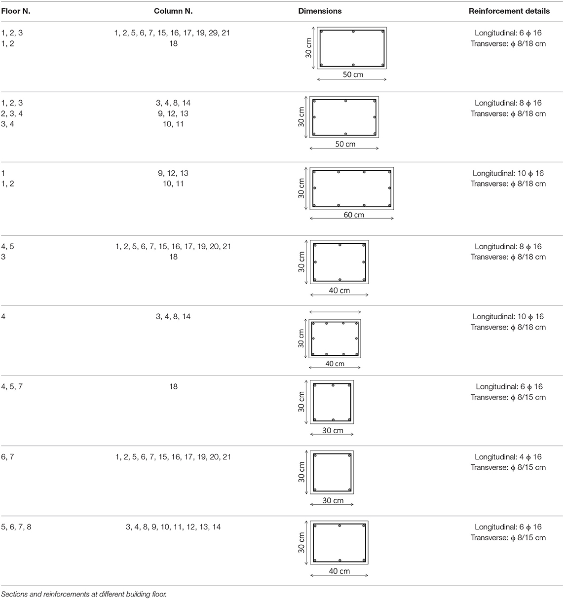
The building has for all floors, one-way RC joists all directed along the transverse direction (Y direction), with hollowed lightening blocks. No internal RC frame along the transverse direction is present. Each floor may be reached through concrete stairs, or else with an elevator hosted within a concrete core made by vertical RC walls running throughout the total building height, and having a thickness of 20 cm. In total, 21 columns compose the 3D building frame, having the dimensions and reinforcements details summarized in Table 1. As for the beams, the principal ones supporting the joists have, at all floor levels, a section of 100 × 25 cm, while the secondary ones have a section 60 × 25 cm. The typical reinforcements, respectively, of principal and secondary beams, are depicted in Figures 2A,B, respectively.

Figure 2. Existing beams. Details of longitudinal and transverse reinforcements related to (A) principal beams (i.e., supporting the joists) and (B) secondary ones (original drawings).
The building was designed in according to the Italian Design Code (NTC, 1992), only for vertical loads without any detailing rule for structural ductility, by applying the allowable stress design method (also called working stress design method). Although the construction period is quite recent, the seismic action was not considered because of the considered area, which was classified by law as not seismic. On the contrary, as it will be discussed later, by referring to current seismic classification (NTC, 2008) the site belongs to a zone having a medium-low seismic intensity.
Materials Properties
Details on the building under consideration were collected firstly from the examination of the complete original design documents, including the original certificates which are related to concrete and reinforcing steel samples tested in the laboratory, as required by the design code adopted for building design (NTC, 1992). However, in situ measurements and tests including extraction of concrete cores were conducted, too. The comparison between the information gathered through the tests campaign and the original documents has demonstrated that the building was realized accordingly to the project approved, without any significant difference.
Precisely, the in situ investigations included dimensional measures of the primary and secondary elements, pacometer investigations, visual assays of elements steel reinforcements (by locally removing the concrete cover), surveys and assays for defining the effective permanent loads. All the in situ inspections were planned and performed by distributing in plan and in elevation as much as possible in the investigations. More in detail: in total 10 concrete cores were extracted from the concrete core walls; 40 coupled pacometric and sclerometric tests were conducted for applying the SONREB method, demonstrating an acceptable homogeneity of concrete within the elements. It should be noted that the concrete cores were extracted from the vertical walls instead of the columns since it was decided of not disturbing these elements that showed at the base of the ground floor an evident degradation state. The results of the average compressive strength experienced in the laboratory on the 10 concrete cores are numerically reported in Table 2, the results of non-destructive tests conducted in the same points where the core were extracted are shown. In addition, in the histogram form, the values of the concrete compressive strength (fc,i), sclerometric rebound index (Si) and ultrasonic velocity (Vi) are reported, each divided by the correspondent average value (fc,m, Sm, Vm). The resulting ratios, for each point investigated, are sorted in according to the increasing ratio fc,i/fc,m. It is important to note that in the case, a really low correlation among the destructive (fc,i/fc,m) and non-destructive measures (Si/Sm, and Vi/Vm) is observed. In conclusion, the average concrete cylindrical compressive strength resulted equal to 19.15 MPa, and is compatible with a concrete class Rbk = 25 MPa, that was the concrete strength used for realizing building components, as resulted in the material certificates of the original project. This value has been assumed as design value for seismic assessment of the building under consideration. As for the reinforcing steel no sample was extracted and the assumed value of the tensile strength has been the one reported in the original material certificate. It resulted in according to a reinforcing steel of class FeB44k, with a characteristic tensile strength equal to fyk = 440 MPa. Therefore, the Knowledge Level (KL) reached, in according to the NTC (2008), resulted equal to KL3, with a Factor of Confidence (FC) equal to 1.
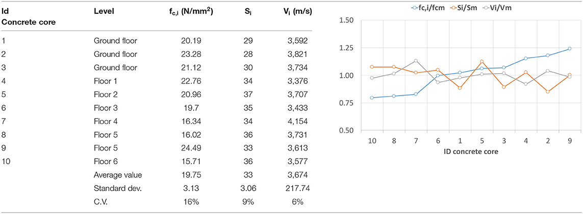
Table 2. Compressive strength of the extracted cores and results of the non-destructive tests conducted.
In summary, the design values for concrete and steel assumed in this study are the following:
• Concrete: fcd = fcm/(γc·FC) = 9.75/(1.5·FC) = 13.16 MPa
• Steel: fyd = fyk/γs = 440/1.15 = 382 MPa.
Site Seismic Hazard and Response Spectra
In this section, the actual seismic hazard of the site is examined. It corresponds to the seismic hazard adopted by the Italian design Code (NTC, 2008) considered for assessing and designing the retrofit interventions later discussed. This seismic hazard remains unchanged in the current Italian design code (NTC, 2018). On the contrary, as already said, the same area was not classified as seismic zone in according to the previous Italian design codes.
Figure 3 illustrates the site seismic hazard and the horizontal response spectra assumed in the numerical simulations when seismic action is considered. More in detail, a nominal life VN = 50 years and coefficient of use CU = 1 are considered, resulting in a reference period VR of 50 years. For completeness, the seismic parameters in conditions of horizontal rigid soil (indicated as Type A soil) are reported for the four Limit State assumed by the reference design code (NTC, 2008), that are: Operativity Limit State (OLS), Damage Limit State (DLS), Life-Safety Limit State (LSLS), Collapse Limit State (CLS). Specifically, the following parameters are detailed (Figure 3A):
• Return period TR;
• Maximum soil accelerations ag in the case of rock soil;
• Maximum spectrum amplification coefficient F0;
• Transition period in the spectrum between constant acceleration and constant velocity.
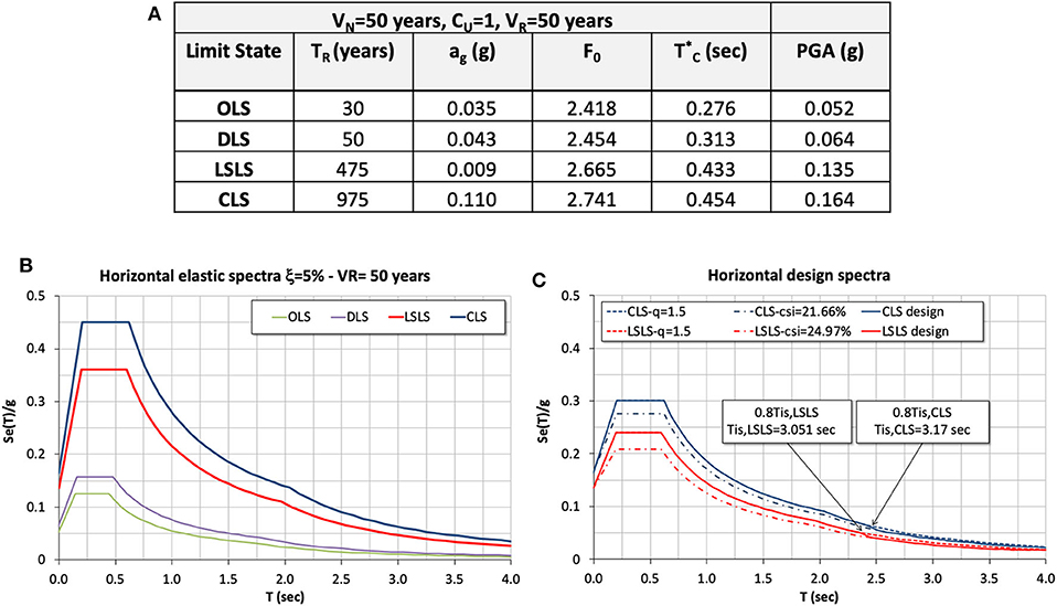
Figure 3. Site seismic hazard and response spectra. (A) Parameters defining the seismic action referred to a rigid soil (Type A) for each limit state, and PGA referred to a soil Type C. (B) Horizontal elastic response spectra (ξ = 5%), and (C) design spectra for LSLS and CLS considering a soil Type C.
The horizontal elastic response spectra for the site considered are reported in (Figure 3B), by referring to a soil of Type C, as resulted in the case analyzed, and to a conventional viscous damping ratio ξ = 5%. While, in Figure 3C design spectra by considering the Fixed-Base (FB) and Base-Isolated (BI) structure are shown. In particular, due to the lack of detailing rules for ductility the horizontal design spectrum for FB model is calculated starting from the elastic one and by assuming conservatively a behavior factor q = 1.5. As for the BI structure, in order to properly take into account the energy dissipated by the isolating system the appropriate design spectrum is calculated as indicated by NTC (2008). Therefore, the design spectra ordinates for LSLS and CLS having a period T ≥ 0.8*Tis (that is the range of isolating system vibration periods) are reduced through the factor as function of the equivalent viscous damping ratio ξeis due to isolation system. As known, ξeis depends on the design horizontal displacement which, in turn, is function of the considered limit state. In this case ξesi results, as it will be discussed later on, equal to 24.97% for LSLS, and to 21.66% for CLS. While, for T < 0.8*Tis the spectra ordinates are coincident with the design ones calculated with a ductility factor q = 1.5 since these ordinates regard the superstructure modes.
Numerical Investigations on “as-Built” Building (Fixed-Base Model)
The existing RC building in the fixed-base (FB) original configuration has been implemented with a FEM model within SAP 2000 software (Computers Structures Inc., 2015). In particular, an elastic model has been adopted, consisting of frame elements for the beams and columns, shells for the elevator core walls and joists. No reduction for flexural and shear stiffness of beams and columns has been considered due to the limited behavior factor assumed for the structure (NTC, 2008). Finally, the model has been fully fixed at the base.
As for the evaluation of the floor masses, they have been calculated in accordance with the following combination:
where Gk1 represents the permanent structural loads, Gk2 are the semi-permanent non-structural loads, and Qkj represent the j-th variable load. In this case we have:
• Housing floors: Gk1+Gk2 = 6.20 kN/m2
• Under-roof floor: Gk1+Gk2 = 3.20 kN/m2
• Roof: Gk1+Gk2 = 3.75 kN/m2
• Live load: Qk =2.00 kN/m2
• Snow load: Qs = 0.60 kN/m2
In all the performed analyses the horizontal seismic action effects are evaluated, together with the vertical loads, through a modal analysis with response spectra where the modal effects are combined with CQC combination rule. For taking into account the directional effects of the seismic action, the following combinations have been considered in evaluating the structural response:
where the multiplier coefficients have been permutated. Moreover, the vertical component of seismic action has been neglected.
Modal Analysis Results
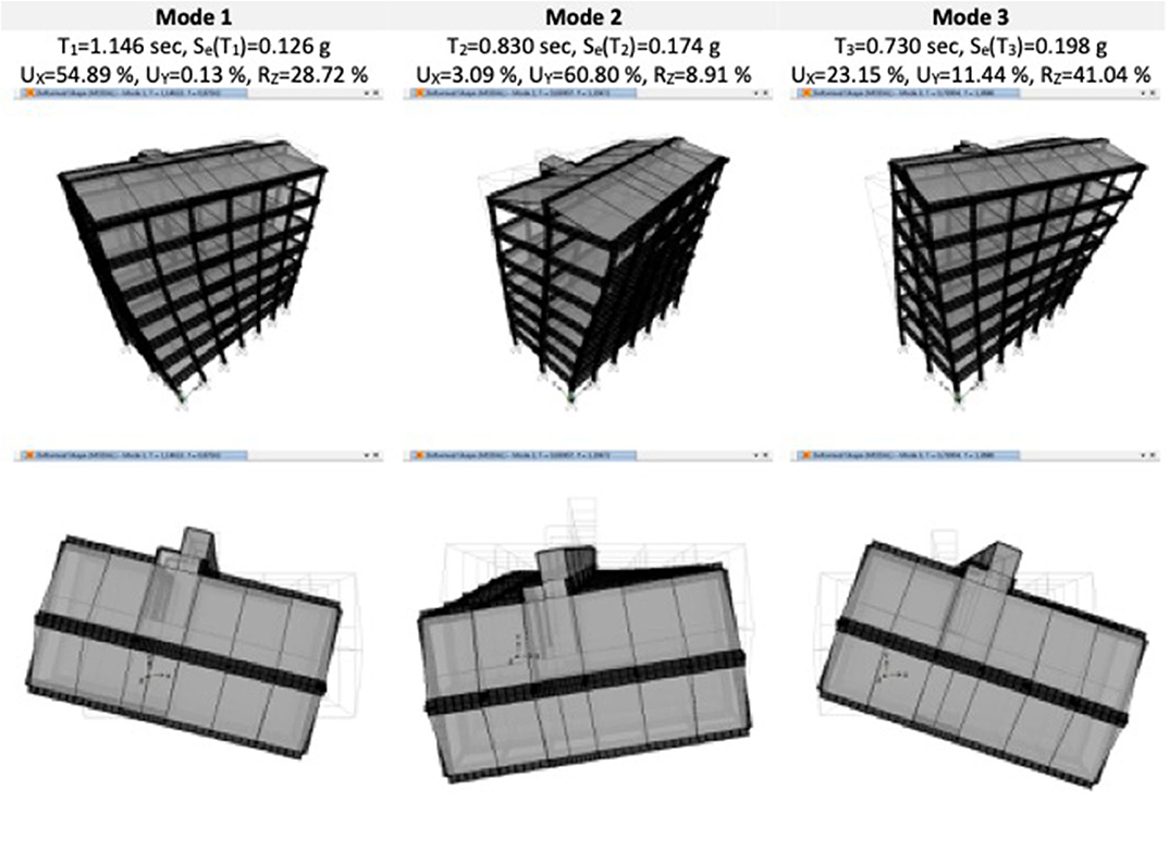
In Figure 4, the results of the first three vibration modes for the FB model are reported. As it is clear to note, all of them result roto-translational modes. In particular, the first mode is rotational and prevailingly translational along X axis (T1 = 1.146 s), the second vibration mode is rotational and prevailingly translational along Y axis (T2 = 0.830 s), while the third is rotational and prevailingly translational again along X axis (T3 = 0.730 s). In Figure 4, also details about the participating mass ratios are illustrated. In particular, the sum of the modal participating mass ratios along the two principal directions (UX and UY), and the rotation mass ratio around Z axis (RZ) are numerically summarized. Finally, the spectral ordinate Se(T) of the LSLS response spectrum of each considered vibration mode is reported.
Structural Verifications
As for the structural verifications for the existing FB building, a modal linear analysis with a design spectrum for LSLS has been conducted. Due to the absence of detailing rules with respect to structural ductility, a behavior factor q = 1.5 has been considered for both verifications of ductile (flexural) and brittle (shear) mechanisms. Overall, as it was simple to expect, by applying the current design code (NTC, 2008) all the beams and columns result verified only with respect to the current vertical loads. Whereas, if one considers the seismic combinations no-one of the primary elements (columns and beams) satisfies the safety verifications. More precisely, the flexural mechanisms do not result verified neither for columns nor for beams. As proof of this, for instance in Figure 5 the columns structural verifications with respect to the design combinations including the seismic action (Equation 2) are reported. As regards the shear verifications, the transverse reinforcement amounts in beams and columns should result sufficient by considering, as indicated by NTC (2008), the secondary shear-resistant mechanisms contribution. However, it should be pointed out that the current stirrups spacing detected respected the detailing of NTC (1992), that indicated a spacing not >0.8 the effective section depth, and therefore not >0.8·23 cm = 18.4 cm.
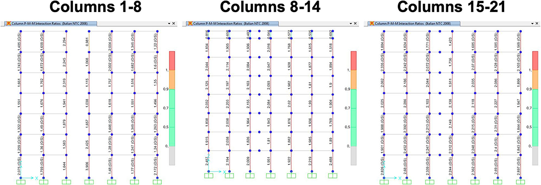
Figure 5. Existing columns. Structural verifications with respect to the axial and bending moment. Verifications are performed with respect to the design combinations including the seismic action.
For completeness, Figure 6A plots for LSLS the floor shear distributions along the two principal directions, by considering separately the seismic action along the longitudinal (EX) and transverse direction (EY) direction. As a useful comparison, in the same figure the resulting shears for the BI model are illustrated, too. It is easy to note that, in the case of FB building the shear distribution is quite non-linear especially for the higher floors. While, in Figures 6B–E are reported for DLS interstory drifts calculated for X and Y directions, by considering the perimetral columns n. 1, 7, 15, and 21 (see Figure 1). These graphs clearly show that the response is irregular with respect to lateral actions due to important torsional effects mainly provoked by the concrete core hosting the elevator. This is proved by the fact that significant interstory drifts occur also along the direction orthogonal to the acting seismic action. In any case the maximum interstory drift does not exceed the 0.5% limit value assumed as maximum allowable for the infills masonry (NTC, 2008).
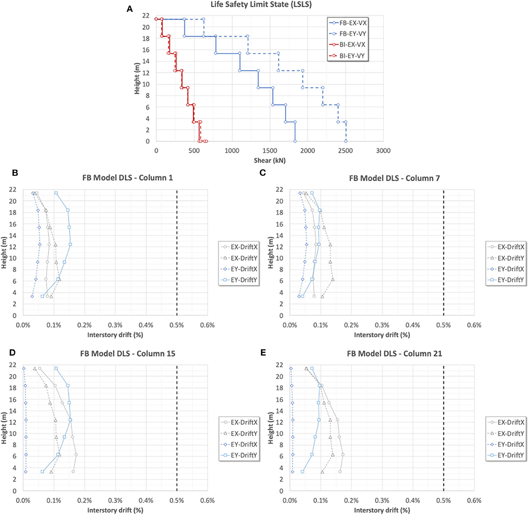
Figure 6. FB model. (A) Shear floor distribution for LSLS. (B–E) Interstory drifts along the X and Y direction for DLS.
Retrofit Strategy With Isolation System at the Base (Base-Isolated Model)
Numerical investigations carried out on the FB model showed that the considered existing building did not satisfy the safety requirements with respect to the seismic actions as required by the refence design code (NTC, 2008). Mainly, all beams and columns resulted as discussed before, the critical elements unable, although the presence of core concrete hosting the elevator to resist to the seismic design actions. This aspect, however, was easily predictable since, as already described, the building was designed only with respect to the vertical loads. Therefore, due to the critical structural aspects encountered, the seismic isolation at the base as retrofit strategy was considered for considerably reducing the seismic demand. Anyway, it should be noted that the building considered had a natural propensity to this retrofit solution, owing to the high grid foundation above which seismic devices may be placed with some local and easy interventions.
In detail, the seismic retrofit intervention was realized as follows. At first, the incoherent back-fill between foundation beams was removed, and concrete columns at foundation grid intersections were created for positioning the isolation devices. Then, above the foundation plan, a grid consisting of steel frames hinged at the columns base with bolted steel joints was installed. This intervention was conducted with the aim of preventing the horizontal relative displacements among the columns at base. Finally, a cut of each singular column at base above the foundation was realized by applying a temporary bearing system with hydraulic jacks for permitting, once the required column part was removed, of installing the isolation device (Figure 7A). In order to improve as well the bearing capacity of columns with respect to the vertical loads, preliminarily to the isolation intervention FRP wraps were applied to the columns up to the fourth floor. The seismic retrofit intervention consisted also of a bracing system, realized through two vertical elastic steel frames laterally applied along the transverse direction (i.e., Y direction, the short direction) for all the building height (Figure 7B). The two frames were made with vertical and diagonal elements having a UPN400 section, welded each other and bolted to the existing RC frame structure. Finally, above the steel frame grid a walking floor with corrugated steel panels was mounted (Figure 7C). As far as the concrete core hosting the elevator is concerned, it was isolated at the base above the foundation plan with a similar procedure applied for the columns. At first, a temporary bearing system with hydraulic jacks was installed in local slots realized in the vertical walls above the existing foundation. Then, a new RC foundation plate above the isolation plan was realized, externally extended for creating a collar necessary for installation of isolation devices (Figures 7D,E). Then, the cut of the walls for removing the walls between the new foundation and the exiting one was completed and the isolation devices were installed (Figure 7F).
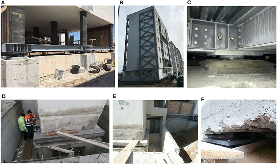
Figure 7. Base-Isolated building. (A) Steel frames grid and seismic device mounted during a construction phase. (B) Lateral view showing the bracing system applied. (C) View a friction slider mounted (view from below the corrugated steel panels). (D,E) Installation of seismic devices under concrete core hosting the elevator. (F) View of the friction slider mounted under a vertical wall.
As for the design of seismic isolation, it consists of flat sliders having a low-friction coefficient for energy dissipation and of elastomeric devices offering re-centering forces during the seismic horizontal oscillations. The isolation system configuration was chosen in order to reduce as much as possible the seismic demand transmitted from the ground to the super structure, through the minimization of the relative eccentricity between center of stiffness and of mass, and by optimizing the equivalent viscous damping ratio and the stiffness of the isolation system.
The schematic layout of the isolation system is shown in Figure 8A, where the devices details are also reported. In total 25 seismic devices were installed: eight elastomeric isolators and 17 flat surface sliders having the properties reported in Figure 8B, with a maximum horizontal design displacement of ± 150 mm. Precisely, as for elastomeric isolators, whose presence is of 32% on the total number of seismic devices installed, it is reported the maximum vertical load capacity in presence of seismic action (PE,max), the lateral stiffness (kH) and the equivalent damping ratio (ξH) of 10%, evaluated in correspondence of the maximum displacement capacity (vmax) equal to ± 150 mm. The 17 flat-surface sliders represent the 68% of the total number of the devices having a friction coefficient μ equal to 1%. In order to optimize their application, three different types of sliders were applied, namely SL-A, SL-B, and SL-C, having a maximum vertical load capacity in presence of seismic action (PE,max) of 1,500, 2,000, and 3,000 kN, respectively.
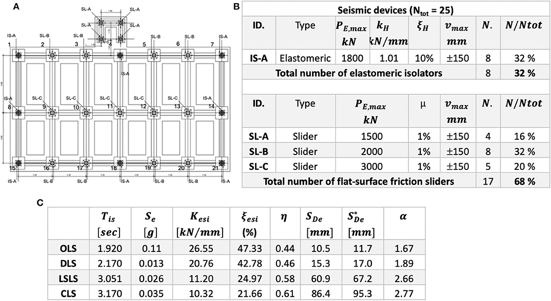
Figure 8. Seismic isolation system: configuration and details. OLS, Operating Limit State; DLS, Damage Limit State; LSLS, Life-Safety Limit State; CLS, Collapse Limit State. (A) Plan of the isolation system, (B) devices details, and (C) properties of the isolation system.
The numerical results of the isolation system design by the means of a modal analysis with design spectrum by using CQC combination rule are summarized in Figure 8C. In the FEM linear model the seismic devices are modeled as linear links, where friction sliders have a secant stiffness at the design horizontal displacement for the limit state considered. In particular, in Figure 8C the following parameters are reported: isolated building period (Tis), spectral acceleration for the period Tis (Se), system secant stiffness (Kesi), equivalent viscous damping ratio (ξesi), reduction factor for the design spectra (η), isolation system maximum horizontal displacement (SDe) occurred when the seismic action acts along each horizontal component, the maximum resulting displacement by considering the torsional effects () (NTC, 2008), and system isolation grade (α = TBI/TFB). In the case considered, the maximum horizontal displacement by including the torsional effects should result equal, at CLS, to 95.3 mm. If one assumes as the worst unfavorable condition that the maximum displacement simultaneously arises along the two principal directions, hence the maximum design displacement should result equal to = √2·95.3=134.75 mm, that is in any case smaller than the maximum displacement capacity of seismic devices (± 150 mm).
As for the modal analysis results, the first three vibration modes are illustrated in Figure 9, by considering the LSLS secant stiffness of seismic devices. As it is easy to note, the interventions considered permit of uncoupling the vibration modes along the two principal directions. The presence of the steel bracing system, by stiffening the superstructure, provides a regular response as rigid block also along the transversal direction (Y direction) and nullifies the superstructure torsional components of two first vibration modes with respect to the FB model (i.e., configuration without interventions where the torsion was dominant).
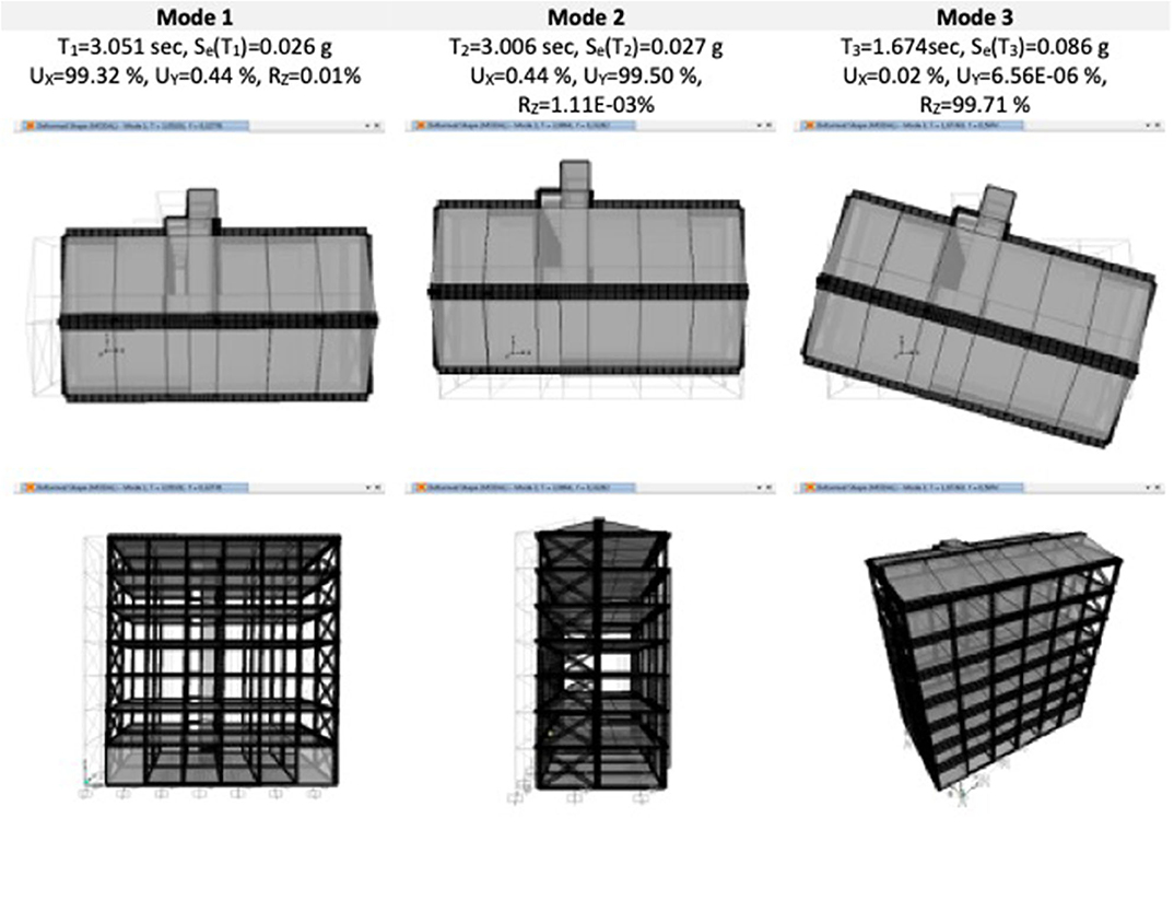
Figure 9. BI model. Shapes and modal properties of the first three vibration modes referred to (secant stiffnesses for LSLS).
Precisely, the first vibration mode now results translational along X axis (T1 = 3.051 s, modal participating mass ratios UX = 99.32%), the second vibration mode is translational along Y axis (T2 = 3.006 s, modal participating mass ratios UY = 99.50%), while the third one is completely rotational (T3 = 1.674 s, modal participating mass ratios RZ = 99.71%).
Figure 10 shows the distribution of floor shears (VX, VY) and forces (FX, FY) along the building height. The graphs refer to the LSLS considering the seismic action acting separately along the X (EX, Figures 10A,B) and Y direction (EY, Figures 10C,D). As one may be observed, in the case of the BI model the shear distributions may result up to five times lower than the ones related to the FB model (Figure 6A). In the comparisons shown, for evaluating the influence of the steel bracing system laterally applied along the Y direction, the structural response with bracing system (considering all significant vibration modes) is compared with the one obtained without bracing system, calculated by referring to the first six vibration modes (three modes of the isolation system + the first three modes of the superstructure). In this case only the bracing system mass is taken into account. As it is easy to note, the superstructure shows along the two principal directions a behavior significantly different. Along the X direction (longitudinal direction, Figure 10B) since no bracing system is applied, an important influence of the higher modes is observed. The floor forces distribution without the bracing system and considering the first with six vibration modes tends to the response obtained with bracing systems. In other words, only the isolated vibration modes (first three modes) are not sufficient to correctly evaluate the floor forces, that are influenced by the higher vibration modes. On the contrary, along the Y direction (short direction, Figure 10D) the presence of the bracing system makes more uniform the floor forces distribution along the height, nullifying the superstructure higher modes contribution. Moreover, as one may clearly observe in Figure 10C the shear acting within the steel bracing system (considering all vibration modes) is always greater than the 50% of the total shear at each building floor. This demonstrates the importance in the case study of the bracing system, revealing it is necessary for regularizing the superstructure response along the Y direction, and for significantly contributing to resist to the seismic action along the transversal direction, where are absent internal RC frames. In fact, even though the spectral ordinates are considerably reduced thanks to the seismic isolation (for instance, almost five times for the first vibration mode reducing from 0.126 to 0.026 g), the absence of the transverse frames and the vulnerability of RC elements has required additional resistant elements, despite the superstructure results in this case perfectly isolated.
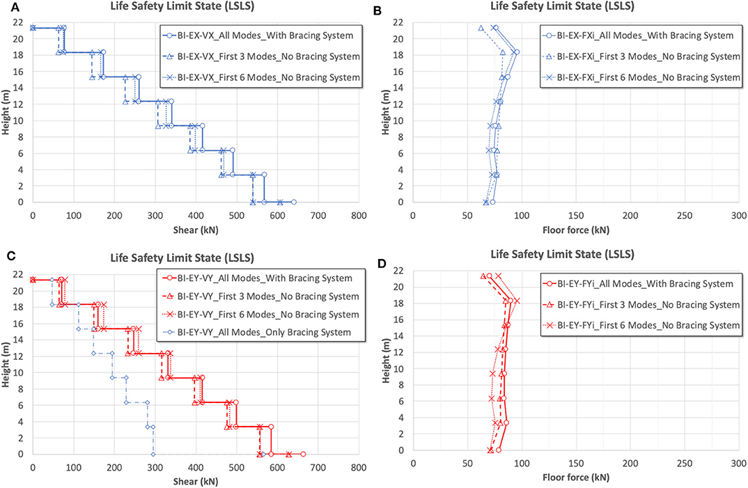
Figure 10. BI model LSLS results. Shears and forces acting at each floor building. (A,B) Shear and floor forces acting along X, and (C,D) along Y direction.
Dynamic Non-Linear Analyses
In order to better evaluate maximum displacement of the isolation system and the effects on the superstructure, several Non-Linear Dynamic (NLD) analyses have been conducted. The numerical model implemented consists of elastic frame and shell elements for modeling the superstructure, and of the zero-length elements for simulating the behavior of the seismic devices. In particular, a frictional behavior (rigid-plastic) is assigned (μ = 1%) to the flat-surface sliders, while the elastomeric devices are modeled as elastic with an equivalent damping ratio (ξH) of 10%. As for the global damping, a 5% modal damping is considered.
In order to perform NLD, a set of seven couples of recorded Ground Motions (GMs) have been selected according to the spectral matching criteria of the Italian Design Code (NTC, 2008). In order to properly consider the bidirectional motion the spectrum- compatibility criterion has been applied to the mean of the SRSS resultants of each couple of GMs between 0.5 and 4 s, by considering a CLS action level. In this way the spectrum compatibility has been ensured for both isolated and superstructure modes.
More precisely, the GMs have been extracted from the database SIMBAD (Smerzini et al., 2014) by using the REXEL software (Iervolino et al., 2009) and elaborated in order to verify the spectrum compatibility of the SRSS combined spectra. Due to the seismic action level considered and the wide range of periods required for spectrum compatibility, it has not been possible to select records coming from a single type of subsoil (i.e., soil Type C). However, the amplitude and shape of the reference spectra account for the soil type conditions. It is worth to note that in order to not alter the GMs characteristics and to improve the interpretability of results no scale factor has been adopted in obtaining the spectrum-compatibility. Therefore, in the analyses performed the GMs considered are unscaled, as suggested in Morelli et al. (2018). Finally, Figure 11 shows the details of each couple selected of GMs, also plotted in the form of horizontal combined spectrum with the SRSS rule. In the same figure the spectrum resulting as mean value of the SRSS combined spectra is compared with the expected one by the design code for CLS.
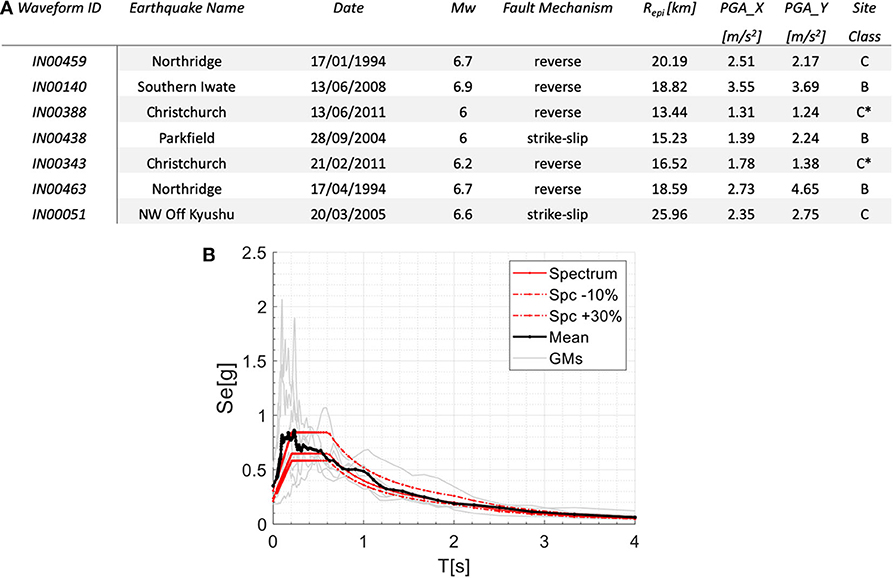
Figure 11. GMs spectra adopted for NLD analyses. (A) GMs characteristics, (B) SRSS spectra of GMs and their mean values compared with expected spectrum for CLS.
In Figure 12 the maximum floor shears occurring in the Y-direction (where steel bracing system is applied) obtained within NLD analyses are shown. Precisely, in Figure 12A and in Figure 12B both braced and unbraced configurations are considered, by reporting the maximum floor shears of each GM couple (gray solid line) and the resulting average on the seven couples (black solid line). It can be noticed that, except for one record (i.e., IN 00051) the maximum floor shears are quite similar among the different GMs. For sake of completeness, Figure 12C separately reports a comparison between the averages of maximum floor shears, also numerically summarized in Figure 12D. As it is clear to observe, the presence of the bracing system reduces at CLS the shear at higher floors up to 18%, confirming the results of linear dynamic analyses.
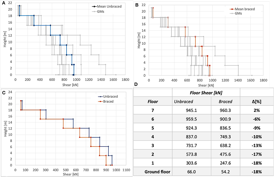
Figure 12. NLD analyses results. (A) Maximum floor shears in Y-direction for the unbraced system. (B) Maximum floor shears in Y-direction for the braced system. (C) Comparison of average values of maximum floor shears between braced and unbraced systems. (D) Comparison of the average values of the maximum floor shears.
As for the isolation system verifications, as example in Figures 13A,B the displacements time-history of the center of mass of the isolated floor (i.e., z = 0 m) along X and Y directions for two GMs couples (i.e., IN00140 and IN00463) are reported. While, in Figure 13C the numerical values of maximum and minimum displacements obtained for each GMs couple are reported. Also, it is reported for each GMs couple the maximum displacement (in absolute value), and the combined one between with the SRSS rule, as well as the mean values of the maximum, minimum, and absolute values. It can be noticed that the average maximum displacements in absolute are 88 and 111 mm along X and Y direction, respectively. These values are in good agreement with the obtained results of linear dynamic analyses exposed in Figure 8C. Moreover, the maximum resultant displacement calculated with the SRSS combination rule is of 129 mm, which is 1.16 times higher than maximum displacement recorded along one of the principal direction (i.e., along Y-direction in this case). This result is in good agreement with the rule discussed in Clough and Penzien (1993) and in Laguardia et al. (2019) in order to assess the maximum resultant displacement. In these studies, it is suggested to amplify the results of a monodirectional analysis by a factor of 1.12 or 1.18 by considering a ratio of earthquake ground motions spectral components of 0.85 and 1, respectively. Nevertheless, the torsional effects are not considered in the NLD analyses performed. In order to emphasize such aspect the maximum resultant displacement is plotted in Figures 13A,B with black dashed lines (symmetrically plotted on positive and negative values) together with the horizontal displacement along X and Y directions (red and blue solid lines, respectively). It can be seen that the maximum value of resultant displacement is quite similar to the maximum value along a single direction and, moreover, the resultant displacement peak occurs at the displacement peak along the same direction.
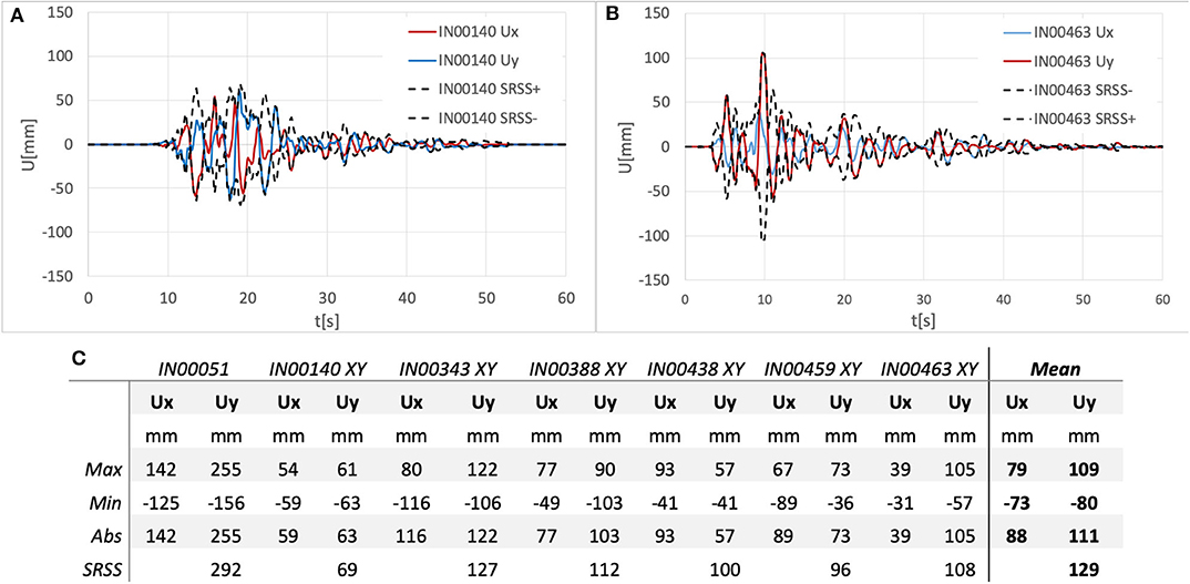
Figure 13. NL dynamic analyses on the case study structure. (A) Displacement history for GM IN00140. (B) Displacement history for GM IN00463. (C) Maximum, minimum, absolute, and resultant (SRSS) values for each GMs and mean values.
Conclusions
An application of the seismic isolation at the base of an existing RC buildings has been presented in this study. The existing building has been designed only for vertical loads since, at construction time, no seismic classification was in existence by law. While, the seismic zones upgrade due to the recent Italian seismic hazard maps classified the area with a medium-low seismic intensity.
The results of the analyses performed highlight the importance of the steel bracing system along the transverse direction in order to increase the stiffness of the superstructure with a consequent reduction of the higher vibration mode effects and, therefore, for making more uniform the seismic demand in terms of forces.
As for the non-linear dynamic analyses results, they have demonstrated that the displacement demand on seismic devices is lower than their maximum displacement capacity. However, some difference may be encountered in combining the effects of the seismic action along the two principal directions. In any case, NLD analyses demonstrate that the maximum value of resultant displacement is quite similar to the maximum value of maximum displacement along a single direction. In addition, the resultant displacement peak takes place at the displacement peak along the same direction.
Data Availability Statement
All datasets generated for this study are included in the article/supplementary material.
Author Contributions
MD'A supervised a part of the intervention realization. All authors contributed to the design and implementation of the research reported, to the analysis of the results and to the writing of the manuscript.
Conflict of Interest
The authors declare that the research was conducted in the absence of any commercial or financial relationships that could be construed as a potential conflict of interest.
Acknowledgments
Authors want to gratefully acknowledge Eng. Carmelo Cotrufo and Eng. Paolo Venezia of ATER technical office for their passion and priceless collaboration and assistance in realizing the interventions on the retrofitted building. Dedicated to the memory of prof. Michelangelo Laterza.
References
Alhan, C., and Gavin, H. (2004). A parametric study of linear and non-linear passively damped seismic isolation systems for buildings. Eng. Struct. 26, 485–497. doi: 10.1016/j.engstruct.2003.11.004
Braga, F., Faggella, M., Gigliotti, R., and Laterza, M. (2005). Nonlinear dynamic response of HDRB and hybrid HDRB-friction sliders base isolation systems. Bulletin Earthquake Eng. 3, 333–353. doi: 10.1007/s10518-005-1242-2
Braga, F., Gigliotti, R., and Laguardia, R. (2019). Intervention cost optimization of bracing systems with multiperformance criteria. Eng. Struct. 182, 185–197. doi: 10.1016/j.engstruct.2018.12.034
Caprili, S., Mattei, F., Gigliotti, R., and Salvatore, W. (2018). Modified cyclic steel law including bond-slip for analysis of RC structures with plain bars. Earthquakes Struct. 14, 187–201. doi: 10.12989/eas.2018.14.3.187
Castellano, A., Foti, P., Fraddosio, A., Marzano, S., Mininno, G., and Piccioni, M. D. (2014). Seismic response of a historic masonry construction isolated by stable unbonded fiber-reinforced elastomeric isolators (SUFREI). Key Eng. Mater. 628, 160–167. doi: 10.4028/www.scientific.net/KEM.628.160
Ciampi, V., De Angelis, M., and Paolacci, F. (1995). Design of yielding or friction-based dissipative bracings for seismic protection of buildings. Eng. Struct. 17, 381–391. doi: 10.1016/0141-0296(95)00021-X
Computers and Structures Inc. (2015). SAP2000 Integrated Solution for Structural Analysis and Design. Berkeley, CA.
Constantinou, M., Mokha, A., and Reinhorn, A. (1990). Teflon bearings in base isolation II: modeling. J. Struct. Eng. 116, 455–474. doi: 10.1061/(ASCE)0733-9445(1990)116:2(455)
D'Amato, M., Gigliotti, R., and Laguardia, R. (2019). Seismic isolation for protecting historical buildings: a case study. Front. Built Environ. 5:87. doi: 10.3389/fbuil.2019.00087
D'Amato, M., Laterza, M., and Casamassima, V. M. (2017). Seismic performance evaluation of a multi-span existing masonry arch bridge. Open Civil Eng. J. 11, 1191–1207. doi: 10.2174/1874149501711011191
De Luca, A., De Mele, E., Molina, J., Verzeletti, G., and Pinto, A. V. (2001). Base isolation for retrofitting historic buildings: evaluation of seismic performance through experimental investigation. Earthquake Eng. Struct. Dynam. 30, 1125–1145. doi: 10.1002/eqe.54
De Matteis, G., Formisano, A., Mazzolani, F. M., and Panico, S. (2005). “Design of low-yield metal shear panels for energy dissipation,” in Improvement of Buildings' Structural Quality by New Technologies - Proceedings of the Final Conference of COST Action C12 (Innsbruck), 665–675. doi: 10.1201/9780203970843.ch77
Formisano, A., Castaldo, C., and Chiumiento, G. (2017). Optimal seismic upgrading of a reinforced concrete school building with metal-based devices using an efficient multi-criteria decision-making method. Struct. Infrastruct. Eng. 13, 1373–1389. doi: 10.1080/15732479.2016.1268174
Formisano, A., De Matteis, G., Panico, S., Calderoni, B., and Mazzolani, F. M. (2006). “Full-scale test on existing RC frame reinforced with slender shear steel plates,” in Proceedings of the 5th International Conference on Behaviour of Steel Structures in Seismic Areas - Stessa 2006 (London), 827–834.
Formisano, A., Lombardi, L., and Mazzolani, F. M. (2016). Full and perforated metal plate shear walls as bracing systems for seismic upgrading of existing RC buildings. Ingegneria Sismica 33, 16–34.
Fuentes, D. D., Baquedano Julià, P. A., D'Amato, M., and Laterza, M. (2019b). Preliminary seismic damage assessment of mexican churches after september 2017 earthquakes. Int. J. Architect. Heritage. doi: 10.1080/15583058.2019.1628323
Fuentes, D. D., D'Amato, M., and Laterza, M. (2019a). “Seismic vulnerability and risk assessment of historic constructions: the case of masonry and adobe churches in Italy and Chile,”in SAHC 2018. 11th International Conference on Structural Analysis of Historical Constructions, RILEM Bookseries. (Cusco) 1127–1137. doi: 10.1007/978-3-319-99441-3_122
Ibrahim, R. A. (2008). Recent advances in nonlinear passive vibration isolators. J. Sound Vib. 314, 371–452. doi: 10.1016/j.jsv.2008.01.014
Iervolino, I., Galasso, C., and Cosenza, E. (2009). REXEL: computer aided record selection for code-based seismic structural analysis. Bulletin Earthquake Eng. 8, 339–362. doi: 10.1007/s10518-009-9146-1
Kawamura, S., Sugisaki, R., Ogura, K., Maezawa, S., and Tanaka, S. (2000). “Seismic isolation retrofit in Japan,” in 12 th World Conference of Earthquake Engineering (Auckland).
Kelly, J. M. (1986). Aseismic base isolation: review and bibliography. Soil Dynam Earthquake Eng. 5, 202–216. doi: 10.1016/0267-7261(86)90006-0
Kelly, J. M. (2002). Seismic isolation systems for developing countries. Earthquake Spectra 18, 385–406. doi: 10.1193/1.1503339
Laguardia, R., Gigliotti, R., and Braga, F. (2017). “Optimal design of dissipative braces for seismic retrofitting through a multi- performance procedure,” in 17th ANIDIS Conference “L'ingegneria Sismica in Italia (Pistoia).
Laguardia, R., Morrone, C., Faggella, M., and Gigliotti, R. (2019). A simplified method to predict torsional effects on asymmetric seismic isolated buildings under bi-directional earthquake components. Bulletin Earthquake Eng. 17, 6331–6356. doi: 10.1007/s10518-019-00686-1
Laterza, M., D'Amato, M., Braga, F., and Gigliotti, R. (2017b). Extension to rectangular section of an analytical model for concrete confined by steel stirrups and/or FRP jackets. Composites Struct. 176, 910–922. doi: 10.1016/j.compstruct.2017.06.025
Laterza, M., D'Amato, M., and Gigliotti, R. (2017a). Modeling of gravity-designed RC sub-assemblages subjected to lateral loads. Eng. Struct. 130, 242–260. doi: 10.1016/j.engstruct.2016.10.044
Martelli, A., and Forni, M. (1998). Seismic isolation of civil buildings in Europe. Progress Struct. Eng. Mater. 1, 286–294. doi: 10.1002/pse.2260010310
Mazza, F., and Vulcano, A. (2014). Equivalent viscous damping for displacement- based seismic design of hysteretic damped braces for retrofitting framed buildings. Bulletin Earthquake Eng. 12, 2797–2819. doi: 10.1007/s10518-014-9601-5
Mokha, A., Constantinou, M., and Reinhorn, A. M. (1988). Teflon Bearings in Aseismic Base Isolation: Experimental Studies and Mathematical Modeling. Technical Report. Buffalo, NY: NCEER.
Mokha, A., Navichandra, A., Constantinou, M. C., and Zayas, V. (1996). Seismic isolation of large historic building. J. Struct. Eng. 122, 298–308. doi: 10.1061/(ASCE)0733-9445(1996)122:3(298)
Morelli, F., Amico, C., Salvatore, W., Squeglia, N., and Stacul, S. (2017). Influence of tension stiffening on the flexural stiffness of reinforced concrete circular sections. Materials 10:669. doi: 10.3390/ma10060669
Morelli, F., Laguardia, R., Faggella, M., Piscini, A., Gigliotti, R., and Salvatore, W. (2018). Ground motions and scaling techniques for 3D performance based seismic assessment of an industrial steel structure. Bulletin Earthquake Eng. 16. doi: 10.1007/s10518-017-0244-1
NTC (1992). Norme Tecniche per L'esecuzione Delle Opere in Cemento Armato Normale e Precompresso e per le Strutture Metalliche D.M. 12 Febbraio (1992). Rome: Italian Ministry of Infrastructure.
NTC (2008). Norme Tecniche per le Costruzioni D.M. 14 Gennaio 2008. Rome: Italian Ministry of Infrastructure.
NTC (2018). D.M. 17.01.18 - Aggiornamento delle ‘Norme Tecniche per le Costruzioni. Rome: Italian Ministry of Infrastructure.
Panzera, I., Morelli, F., and Salvatore, W. (2020). Seismic multi-level optimization of dissipative re-centering systems. Earthquake Struct. 18, 129–145.
Petrovčič, S., and Kilar, V. (2017). Seismic retrofitting of historic masonry structures with the use of base isolation - modeling and analysis aspects, Int. J. Archit. Heritage 11, 229–246. doi: 10.1080/15583058.2016.1190881
Ramírez, E., Lourenço, P. B., and D'Amato, M. (2019). “Seismic assessment of the matera cathedral,” in Proceedings of SAHC 2018. 11th International Conference on Structural Analysis of Historical Constructions, RILEM Bookseries, in 18. (Cusco), 1346–1354. doi: 10.1007/978-3-319-99441-3_144
Rossi, E., Sebastiani, M., Gigliotti, R., and D'Amato, M. (2020). An innovative procedure for the in-situ characterization of elastomeric bearings by using nanoindentation test. Int. J. Archit. Heritage. 1–13. doi: 10.1080/15583058.2020.1737986
Smerzini, C., Galasso, C., Iervolino, I., and Paolucci, R. (2014). Ground motion record selection based on broadband spectral compatibility. Earthquake Spectra 30, 1427–1448. doi: 10.1193/052312EQS197M
Keywords: seismic isolation, seismic devices, retrofit, existing RC building, steel bracing structure
Citation: D'Amato M, Laguardia R and Gigliotti R (2020) Seismic Retrofit of an Existing RC Building With Isolation Devices Applied at Base. Front. Built Environ. 6:82. doi: 10.3389/fbuil.2020.00082
Received: 31 January 2020; Accepted: 06 May 2020;
Published: 09 July 2020.
Edited by:
Panagiotis G. Asteris, School of Pedagogical and Technological Education, GreeceReviewed by:
Amin Mohebkhah, Malayer University, IranAli Koçak, Yıldız Technical University, Turkey
Copyright © 2020 D'Amato, Laguardia and Gigliotti. This is an open-access article distributed under the terms of the Creative Commons Attribution License (CC BY). The use, distribution or reproduction in other forums is permitted, provided the original author(s) and the copyright owner(s) are credited and that the original publication in this journal is cited, in accordance with accepted academic practice. No use, distribution or reproduction is permitted which does not comply with these terms.
*Correspondence: Michele D'Amato, bWljaGVsZS5kYW1hdG9AdW5pYmFzLml0
 Michele D'Amato
 Raffele Laguardia
 Rosario Gigliotti