 Yuantao Ding
 Zhengtao Wang
 Peizhong Yang
 Suiran Yu
94% of researchers rate our articles as excellent or good
Learn more about the work of our research integrity team to safeguard the quality of each article we publish.
Find out more
ORIGINAL RESEARCH article
Front. Bioeng. Biotechnol., 27 February 2025
Sec. Biomechanics
Volume 13 - 2025 | https://doi.org/10.3389/fbioe.2025.1551039
This article is part of the Research TopicBiomechanics, Sensing and Bio-inspired Control in Rehabilitation and Assistive Robotics, Volume IIView all 10 articles
Introduction: Lower limb exoskeleton robots for young children with cerebral palsy (CP) are crucial to support earlier rehabilitation that is more beneficial than later. For safety reasons, pediatric exoskeletons are usually equipped with body weight support (BWS) devices to help young patients maintain balance. However, existing pediatric exoskeletons tend to use stiff joint actuation and passive BWS with limited compliance.
Method: This paper proposes a novel mobile exoskeleton robot for young children (3- ∼ 6-years-old) with CP based on intrinsically compliant actuation. A compact kinematic chain that integrates an exoskeleton, an active BWS system, and a walker is proposed. Furthermore, with the actuation design optimization of the kinematic chain, the robot can walk alone stably in passive rehabilitation and provide high compliance in active rehabilitation. The exoskeleton adopts actuation similar to the quasi-direct drive paradigm to acquire high mechanical compliance and uses a secondary planetary reducer to ensure high output torque. Assistive torque control is achieved through proprioceptive sensing instead of torque sensors. The BWS system uses a series elastic actuator to accurately generate the weight support force and significantly reduce the fluctuation of the support force compared to the passive BWS.
Results and discussion: Finally, control frameworks for passive and active rehabilitation are implemented to validate the robot performance. The experimental results demonstrate that our robot can support safe and compliant rehabilitation.
Cerebral palsy (CP) is a common movement disorder in children, affecting approximately 1.6% ∼ 3.4% of newborns (McIntyre et al., 2022), severely impairing their ordinary life and growth. Conventional treatment depends on the experience and labor of rehabilitation therapists (Aisen et al., 2011). However, with the development of rehabilitation robotics, new approaches have emerged, opening up new possibilities for enhancing pediatric rehabilitation. For instance, several clinical studies have demonstrated the effectiveness of robot-assisted gait therapy (RAGT) (Jin et al., 2020) and partial body weight support treadmill training (PBWSTT) (Willoughby et al., 2010) in improving postural and motor function in children with motor impairments. In recent years, some lower limb orthoses and exoskeletons have been developed for children with CP, offering the potential to supplement traditional physical rehabilitation (Gonzalez et al., 2021; Sarajchi et al., 2021).
Stationary gait rehabilitation systems, such as Lokomat (Wallard et al., 2017) and Walkbot (Jin et al., 2020), were the first to be clinically applied. They assist patients with natural gait rehabilitation through the coordinated movement of the exoskeleton and the treadmill. However, their high cost and large size limit them to rehabilitation clinics. Wearable exoskeletons (Patané et al., 2017; Lerner et al., 2018; Eguren et al., 2019) can provide gait correction while allowing patients to walk on the ground. They have the potential to facilitate home-based rehabilitation and offer greater benefits to pediatric patients (Ding et al., 2024a). Rehabilitation safety is often cited as a primary consideration (Wang et al., 2023). To ensure this safety, most wearable exoskeletons must be used with crutches for dynamic balance and fall prevention (Qiu et al., 2023). However, this is impractical for children with CP at a low age, who benefit more from earlier rather than later intervention (Patel et al., 2020). In order to maintain the balance of the human-robot system and facilitate earlier rehabilitation when patients are weak (Bayón et al., 2017), some studies have attached exoskeletons to support devices (Maggu et al., 2018; Llorente-Vidrio et al., 2020; Narayan and Kumar Dwivedy, 2021; Cumplido-Trasmonte et al., 2022). For example, ATLAS 2030 (Cumplido-Trasmonte et al., 2022) mounted the exoskeleton to a particular frame, while Trexo (Maggu et al., 2018) added the exoskeleton to a commercial walker. However, combining the exoskeleton with a simple support mechanism only provides passive body weight support (BWS) and limits flexibility at the attachment point.
Compliant human-robot interaction (HRI) is also essential for safety and comfort in rehabilitation (Gong et al., 2024). Compared to passive BWS, active BWS systems can compliantly control the body weight support force. However, they also increase the complexity of structure and control. Moreover, existing stationary BWS systems are usually complicated and heavy (Dong et al., 2021b; Mokhtarian et al., 2023), while mobile BWS systems (Dong et al., 2021a; Kwak et al., 2022; Stramel et al., 2023) are commonly developed separately without integrated exoskeletons. Therefore, it is still a challenge to integrate an exoskeleton with an active BWS system while remaining compact and lightweight. Most existing studies on the compliant control of pediatric exoskeletons have used low - torque motors with high gear ratios. These are also known as traditional stiff actuators (TSAs) (Bayón et al., 2017; Andrade et al., 2019). They are typically equipped with torque sensors to achieve active compliance through feedback control (Zhu et al., 2022), such as dynamic compensation control (Andrade et al., 2019) and impedance control (Bayón et al., 2017). However, TSAs are not backdrivable and lack mechanical compliance, motivating researchers to enhance the intrinsic compliance of the actuators from the mechanical design. For example, WAKE-Up (Patané et al., 2017) employed a series elastic actuator (SEA) to design the exoskeleton joint, which increased compliance by adding torsion springs and belts between the motor and the load.
Research on compliant actuation has mainly focused on adult rehabilitation so far. In this area, several novel actuation methods have been proposed to improve robotic performance. Variable stiffness actuators (VSAs) have been developed for both exoskeletons (Liu et al., 2024) and BWS systems (Dong et al., 2021a) to adjust the stiffness of the elastic element to match the stiffness requirements of different gait events. However, they inevitably increase the volume and mass of the robot, which poses a challenge in the confined space arrangement of pediatric rehabilitation robots. Quasi-direct drive (QDD) actuation (Ding et al., 2024b) uses high-torque motors and small transmission ratios (≤10:1), resulting in low mechanical impedance and high compliance. However, due to the small transmission ratio, the output torque is low and currently suitable for applications where only partial assistance is required. Although the design constraints of rehabilitation robots differ significantly between adults and children, these novel actuation paradigms also inspire the design of the pediatric exoskeleton and the active BWS system in this work.
This paper presents a novel children’s mobile exoskeleton robot (hereafter referred to as ChMER, see Figure 1) for overground gait rehabilitation of young children with CP. Table 1 shows the comparison of ChMER with other similar pediatric rehabilitation robots, indicating that the existing robots mainly use passive BWS with limited compliance, while the robot (Bayón et al., 2017) with an active BWS system is unsuitable for young children. Moreover, although SEAs, VSAs, and QDD actuators have demonstrated excellent performance and application value in adult rehabilitation devices, TSAs are still dominant in the existing pediatric rehabilitation robots. Therefore, based on the intrinsically compliant actuation, this work focuses on the compact mechatronic design of ChMER with an active BWS system, which can accommodate the limited size of young children’s limbs while providing compliant and safe HRI. The main contributions of this work are: 1) proposing a compact kinematic chain that integrates an exoskeleton, an active BWS system, and a walker and designing the actuation patterns for passive and active rehabilitation; 2) developing and validating the pediatric exoskeleton and the active BWS system with the compliance-oriented design concept based on multifactorial trade-off analysis of the intrinsically compliant actuation. The exoskeleton adopts actuation similar to the QDD paradigm to improve mechanical compliance and uses a secondary planetary transmission to provide high output torque. Torque control is achieved through current-based proprioceptive torque sensing rather than torque sensors. The BWS system uses an SEA with a mechatronic design to accurately generate and sense the weight support force in the vertical direction. Furthermore, control frameworks for passive and active rehabilitation are implemented based on the above.
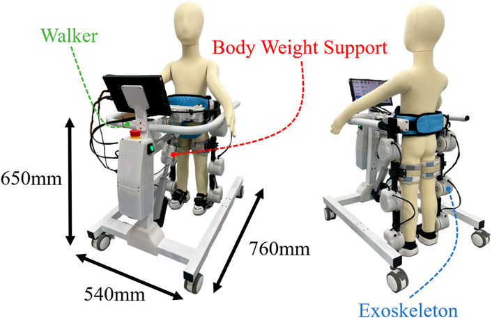
Figure 1. Overview of the proposed mobile exoskeleton robot (ChMER) with an active body weight support walker for young children with CP.
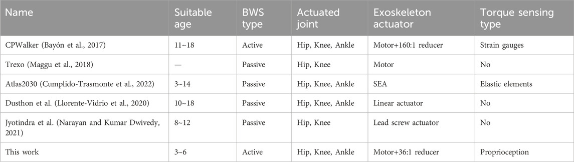
Table 1. Comparisons with some other mobile exoskeleton rehabilitation robots for children.
Clinical studies (Alriksson-Schmidt et al., 2017; Burgess et al., 2022) have shown that children with CP are expected to reach 90% of their motor - developmental potential by the age of five and then reach a plateau. Hence, early intervention is critical to optimize the motor function of the affected children (Damiano, 2006). Therefore, the target population for ChMER is selected to be 3- to 6-years-old children at Gross Motor Function Classification System (GMFCS) levels II to V. GMFCS levels range from I to V, with the motor function of children gradually deteriorating as the level increases. The design criteria for the robot are as follows. First, ChMER should adapt to the tiny limbs of young children and have an active BWS system to ensure safety and comfort during rehabilitation training while maintaining a simple structure to increase reliability and reduce cost. In addition, ChMER should provide a variable assistance mode to adapt to the different motor abilities of the patient. Specifically, children at GMFCS levels II and III have a certain degree of independent walking ability. In contrast, those at GMFCS levels IV and V usually cannot walk independently. Therefore, the robot should provide complete assistance for passive rehabilitation in children with no active motor ability (GMFCS levels IV and V) and adjustable compliant assistance for active rehabilitation in children with partial motor ability (GMFCS levels II and III).
According to the study of the peak joint torque of healthy children during normal walking (Chester et al., 2006), for the children weighing 25 kg, the peak torques of the hip, knee, and ankle joints are about 22.5, 17.5, and 37.5 Nm, respectively. Therefore, the peak output torque of the exoskeleton joint is required to reach these joint torques. Moreover, according to the lower limb size of three-year-old children (Tilley and Associates, 2002), the maximum diameter of the exoskeleton joint is limited to 90 mm. The BWS system should be able to reduce 70% of the children’s body weight. Therefore, it is required to provide a maximum weight unloading of approximately 175 N. The design requirements and actual parameters are summarized in Table 2.
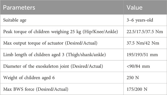
Table 2. Design parameters of ChMER.
The design concept of ChMER is derived from the manual treatment by a therapist, as illustrated in Figure 2A, which aims to provide joint assistive torque
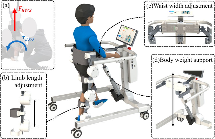
Figure 2. Basic structure of ChMER. (A) The design concept derived from the manual treatment. (B) The adjustment mechanisms of the limb length and (C) waist width. (D) The body weight support system.
Unlike previous studies (Maggu et al., 2018) that design the exoskeleton and the BWS system separately, we integrate them into a continuous kinematic chain with a walker instead of isolated components, which enhances the system’s compactness. The mechanism sketch of the robot is shown in Figure 3A, where the walker is simplified as a translational joint (
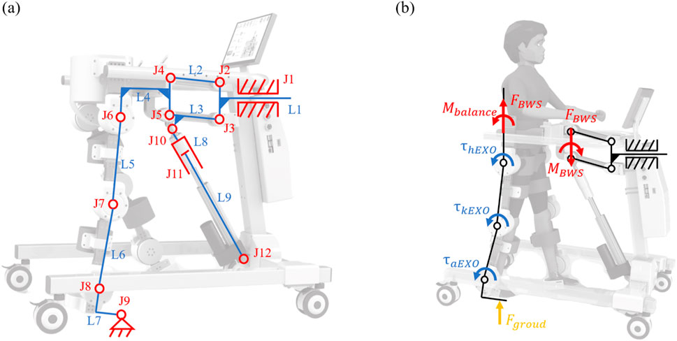
Figure 3. Kinematics and force diagram of ChMER. (A) Mechanism sketch of the compact kinematic chain. (B) Force diagram of the support leg during walking.
For passive rehabilitation, the robot needs to follow a predefined trajectory. In Equation 1, the 3 DoFs refer to the number of independent motion parameters that must be specified for the mechanism to have a definite motion. In other words, it is equal to the number of prime movers required to move the walker forward. Therefore, it is necessary to select three of the hip, knee, and ankle joints (
For active rehabilitation, the movement of the system is dominated by the children, requiring ChMER to be able to apply assistive forces as needed. The diagram of the dynamic analysis of the human-robot system during walking is shown in Figure 3B. Considering the support leg as tandem type joints and the waist as the base, the coupled human-robot dynamic model of the support leg can be obtained as follows:
where
From Equations 2 and 3, it can be seen that
As the core element of ChMER, proper actuation is essential to improve the compliance and transparency of the robot. However, it is difficult for the robot to achieve complete transparency in practice, requiring a multifactorial trade-off. Therefore, this section discusses the actuation design analysis of the exoskeleton and the BWS system.
A typical exoskeleton joint is shown schematically in Figure 4. The expression for its output torque
where
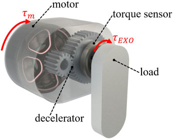
Figure 4. A typical exoskeleton joint.
In terms of improving the transparency of the exoskeleton joint, the transmission ratio
Due to the small acceleration
Then the closed-loop control of
The design requirement of the exoskeleton joint is to have enough output torque without excessively increasing the mechanical impedance to maintain the backdrivability and transparency. Therefore, based on the analysis in Section 3.1, we adopt the actuator (customized from Haitai Electromechanical, China) that uses a secondary planetary reducer (Figure 5B) with a total transmission ratio of 36:1. The nominal torque of the actuator is 18 Nm, the peak torque is 42 Nm, and the backdriving torque is tested to be within 1 Nm, with the mass of 580 g and the size of
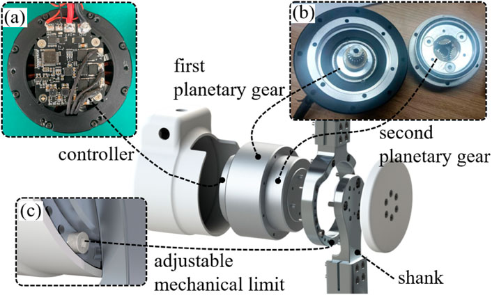
Figure 5. Overall design of the exoskeleton joint. (A) Controller. (B) Secondary planetary reducer. (C) Adjustable mechanical limit for different ranges of joint motion of children with CP.
The expression for the output force
where
where
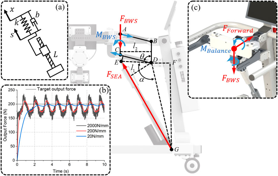
Figure 6. Analysis of the BWS system. (A) Diagram of the connection between the linear actuator and the load. (B) The simulation results of tracking 200 N for different
Although the control object
The angle
Finally, by combining Equations 13–15, the length of
In controlling
The design of the SEA is shown in Figure 7A, which includes a linear actuator (customized from Hoodland, China), a die spring, a piston device, and a force sensor (DYZ-102, DAYSENSOR). Usually, SEAs realize force sensing by measuring the compression of the elastic element. However, in order to improve compactness, a force sensor is used instead of the displacement sensor that requires a large installation volume. It can be seen from Equation 10 that the compliance and dynamic performance of the SEA are related to the stiffness of the elastic element. For children with severe motor injuries, the stiffness needs to be reduced to improve compliance and comfort. For children with partial motor abilities, the stiffness needs to be increased to accommodate relatively more dynamic movements. Therefore, a quick-release structure (Figure 7B) is adopted to conveniently replace the die springs that are available in a variety of stiffnesses with the same size specification to meet different children’s needs. In order to realize the highly mechatronic design of the BWS system, as shown in Figure 7C, the custom controller is mounted on the rotary joint of the four-bar structure. Therefore, the angle
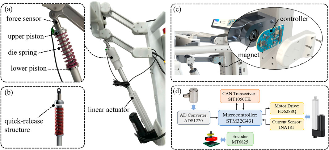
Figure 7. Overall design of the BWS system. (A) Design of the SEA; (B) Quick-release structure of the SEA for easy spring replacement. (C) Controller mounted on the rotary joint. (D) The hardware structure of the controller.
This section presents the hardware architecture of the control system and the control methods for passive and active rehabilitation. The exoskeleton and the BWS system are designed with transparency in mind. This design allows the transformation of
A three-level control structure is adopted to ensure security during rehabilitation, as shown in Figure 8, including the low-level, high-level, and user-level. At the user level, a Raspberry Pi 4b is responsible for human-computer interaction and data storage. The user level communicates with the high-level host board via the serial peripheral interface (SPI) bus to send basic commands such as start-stop and to obtain robot status information. All real-time motion controllers run on the host board that uses a high-performance microcontroller (STM32H743, STMicroelectronics) and FreeRTOS as the real-time operating system. In this way, the isolation between the user level and the high level is achieved so that the motion controllers, which are directly related to safety, are not affected by the user-level software. The low level contains the drivers for the exoskeleton joints and the BWS system, which receive and execute motion control commands from the host board and return status information via the CAN bus.
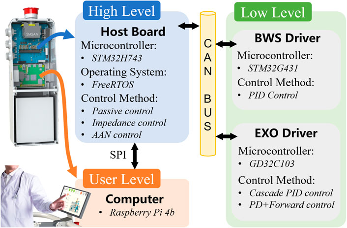
Figure 8. Hardware architecture of the control system.
The control block diagram for passive rehabilitation is shown in Figure 9. The BWS system tracks a predefined support force
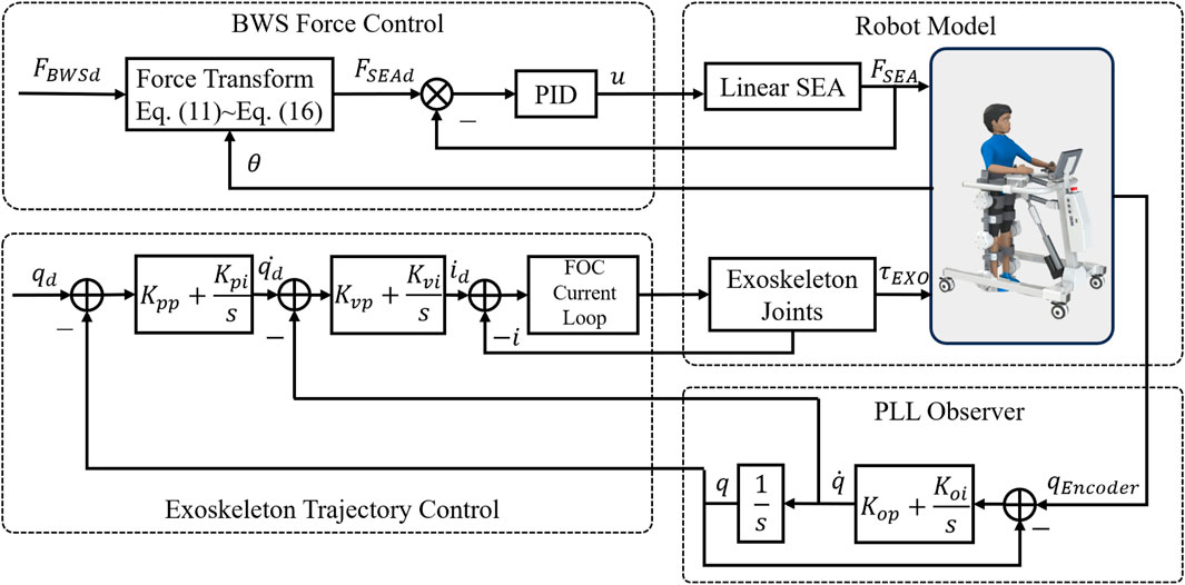
Figure 9. Control block diagram for passive rehabilitation.
The control block diagram for active rehabilitation is shown in Figure 10. The BWS system still uses the above control method, while the exoskeleton adopts the proprioception-based impedance control. Let the assistive torque
where
where
where
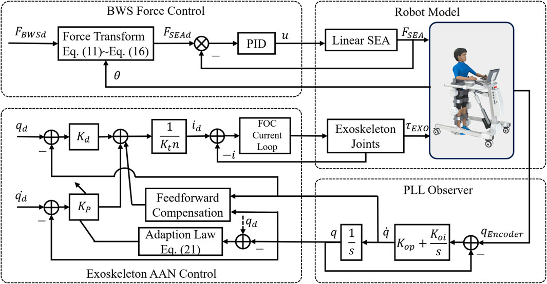
Figure 10. Control block diagram for active rehabilitation.
Based on the impedance control, an AAN strategy (Maggioni et al., 2018) is implemented to automatically adjust the impedance parameters according to the joint tracking errors that relate to the patient’s training performance. The virtual spring stiffness is updated by the tracking errors with the adaptation law as follows.
where
The test performance of the robot can be seen in the Supplementary Video S1.
In order to evaluate the negative effect of the secondary planetary reducer on the transparency of the exoskeleton joint, a test platform shown in Figure 11A is constructed using a torque sensor (HLT-171, Hualiteng Technology) with a measurement accuracy of 0.3% F.S. to measure the actual output torque. First, the torque constant of the motor is calibrated, and the result is shown in Figure 11B, which shows that the output torque has a high linear correlation with the current. The backdrive torque of the exoskeleton joint, which is in the unpowered mode during the measurement, is shown in Figure 11C. It is within ±1Nm when the exoskeleton joint is manually rotated back and forth at the output side with a cycle of about 5 s. Finally, the proprioceptive sensing accuracy is tested under dynamic conditions. The interaction torque is applied to the output side by the human hand while the exoskeleton joint is rotated with the hip gait curve. The estimated interaction torque (blue solid line) and the measured torque sensor value (red dashed line) are shown in Figure 11D, where the estimated value is calculated by substituting the actual motor current into Equation 6. The root mean square (RMS) error is 0.54 Nm, which is about 5.4% of the peak amplitude.
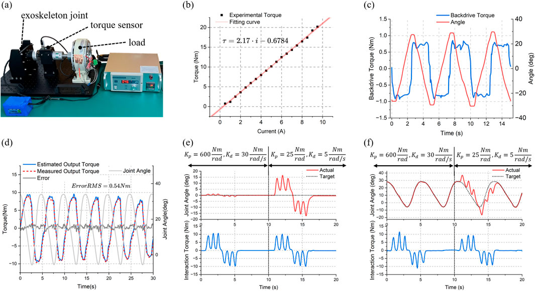
Figure 11. Test results of the exoskeleton joint. (A) Test platform. (B) Current versus torque curve. (C) Backdrivability test (within 1 Nm backdriving torque). (D) Proprioceptive torque sensing accuracy test (0.54 Nm RMS estimated error). Impedance control test of the joint under (E) static condition and (F) dynamic condition.
The above results indicate that even with the additional impedance from the secondary planetary gear, the exoskeleton joint maintains high mechanical compliance. After friction compensation under walking - speed conditions, it also demonstrates high proprioceptive sensing accuracy. This provides a basis for impedance control. The test results of a single exoskeleton joint under static and dynamic conditions are presented in Figure 11E and (f) respectively. The first 10 s were set with larger virtual spring and damping parameters (
The accuracy of the conversion model of
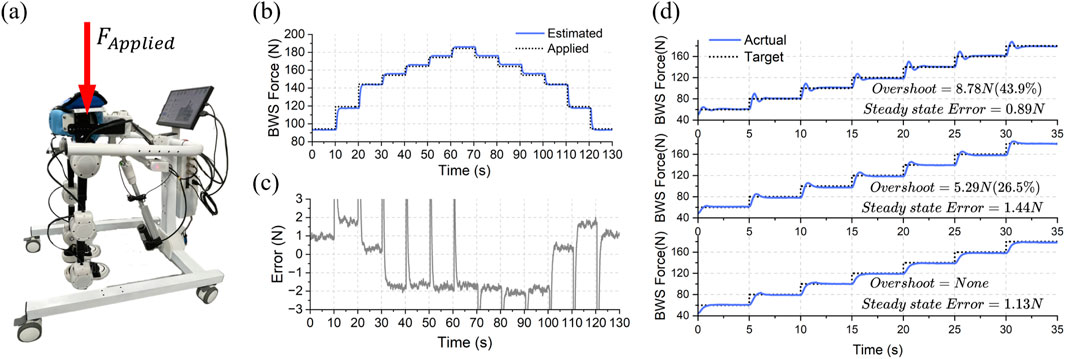
Figure 12. Test results of the BWS system. (A) Method of testing the accuracy of the conversion model by stacking weights as the reference force. (B) The estimated support force and actual force applied. (C) The error between estimated and applied force (within about ±2N). (D) The step response performance of the BWS system.
The performance of ChMER in passive rehabilitation is demonstrated in this section. Since the robot is still in the prototype validation phase, for safety reasons, sandbags were used to simulate the children with a load of approximately 3 kg on the thighs and 2.5 kg on the calves on each side. As described in Section 2.2, ChMER is designed to walk stably on its own. This ability is verified by the independent ground - walking test shown in Figure 13A. The trajectory tracking effect of the cascade PID controller is shown in Figure 13B, where the maximum tracking errors of each exoskeleton joint are within ±0.5°. Finally, during the dynamic process of the robot walking on the ground, the performance of the BWS system was tested by tracking the desired
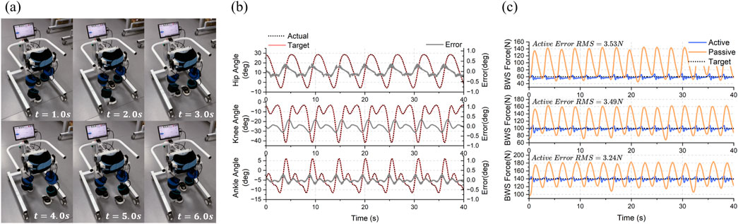
Figure 13. Experimental results of passive rehabilitation control framework. (A) Independent ground walking test of ChMER. (B) Trajectory tracking results (within ±0.5 degrees of error). (C) The active and passive support force during dynamic walking.
The performance of ChMER in active rehabilitation under different constant impedance parameters is shown in Figures 14A, B. Due to the gravity of the sandbags used as the load, the exoskeleton deviated from the desired trajectory in the first 20 s. In the second 20 s, by using the hand to simulate the active torque of the user, the exoskeleton returned to the desired trajectory, and the assistive torque provided by the exoskeleton in Figure 14A was less than that in Figure 14B due to the smaller virtual spring stiffness
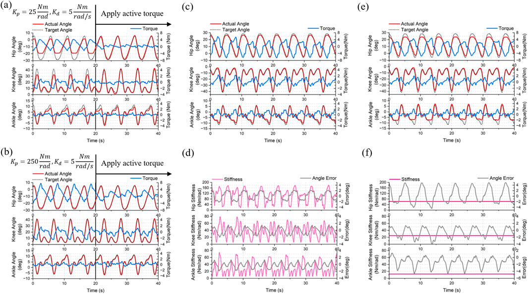
Figure 14. Experimental results of the active rehabilitation control framework. Impedance control with constant parameters of (A)
These results show that ChMER is capable of adjusting the assistive torque on demand. Although this AAN strategy simply modifies the impedance control parameters, its successful implementation also demonstrates that the proposed robot has the potential for further applications of intelligent AAN control algorithms, such as using Gaussian radial basis functions (RBFs) to identify the patient’s residual motor ability and adaptively modify the assistive torque (Luo et al., 2019; Wang et al., 2022).
In this work, we developed a novel mobile exoskeleton rehabilitation robot (ChMER) with an active BWS walker for young children (3- ∼ 6 years-old) with CP. ChMER has high compliance while maintaining a compact structure to accommodate the small limbs of young children. We proposed a compact kinematic chain that integrates an exoskeleton, an active BWS system, and a walker. With the analysis and appropriate actuation setting of the kinematic chain, ChMER is able to walk stably on its own to ensure the safety of passive rehabilitation. It can also adapt to the varying CoMH thanks to the active BWS system, which significantly reduces the fluctuation (about 80%) of the weight support force compared to the passive BWS, thus improving the compliance. Based on the intrinsically compliant actuation, ChMER also supports compliant force control in active rehabilitation. The exoskeleton joint, inspired by the QDD paradigm, maintains high mechanical compliance (1 Nm backdrive torque) and uses a secondary planetary reducer (ratio = 36:1) to ensure high output torque (18 Nm nominal torque). It also has a high proprioceptive torque sensing accuracy of 0.54 Nm RMS error (5.4% of the peak amplitude) under walking speed conditions to realize assistive torque control, which can replace the torque sensor and help reduce the cost and complexity of the robot. The BWS system uses an SEA to accurately generate the support force with 3.53/3.49/3.24 N RMS tracking errors for desired support forces of 60/100/140 N during dynamic walking. Finally, an AAN control strategy based on impedance control is applied as an implementation of active rehabilitation control. ChMER exhibits the desired compliance, demonstrating its potential for further applications of intelligent AAN control algorithms.
The limitation of this work is that there is no performance study with real users, as it focuses on design validation and performance testing of the proposed rehabilitation robot. In future work, we will further improve the structure of the robot and investigate the performance of real users, such as kinetics and electromyography, and validate the effectiveness of the robotic rehabilitation therapy on children with CP. The proposed rehabilitation robot can potentially provide a more effective and convenient rehabilitation solution for children with CP.
The original contributions presented in the study are included in the article/Supplementary Material, further inquiries can be directed to the corresponding author.
YD: Investigation, Methodology, Software, Validation, Visualization, Writing–original draft, Writing–review and editing. ZW: Methodology, Validation, Visualization, Writing–review and editing. PY: Conceptualization, Writing–review and editing. SY: Conceptualization, Funding acquisition, Methodology, Writing–review and editing.
The author(s) declare that financial support was received for the research, authorship, and/or publication of this article. This research was supported by the National Key Research and Development Program of China (Grant 2023YFC3604803). This research was also supported by the National Natural Science Foundation of China (Grant No. 82072042).
The authors declare that the research was conducted in the absence of any commercial or financial relationships that could be construed as a potential conflict of interest.
The author(s) declare that no Generative AI was used in the creation of this manuscript.
All claims expressed in this article are solely those of the authors and do not necessarily represent those of their affiliated organizations, or those of the publisher, the editors and the reviewers. Any product that may be evaluated in this article, or claim that may be made by its manufacturer, is not guaranteed or endorsed by the publisher.
The Supplementary Material for this article can be found online at: https://www.frontiersin.org/articles/10.3389/fbioe.2025.1551039/full#supplementary-material
Aisen, M. L., Kerkovich, D., Mast, J., Mulroy, S., Wren, T. A., Kay, R. M., et al. (2011). Cerebral palsy: clinical care and neurological rehabilitation. Lancet Neurol. 10, 844–852. doi:10.1016/S1474-4422(11)70176-4
Alriksson-Schmidt, A., Nordmark, E., Czuba, T., and Westbom, L. (2017). Stability of the Gross Motor Function Classification System in children and adolescents with cerebral palsy: a retrospective cohort registry study. Dev. Med. Child. Neurol. 59, 641–646. doi:10.1111/dmcn.13385
Andrade, R. M., Sapienza, S., and Bonato, P. (2019). Development of a “transparent operation mode” for a lower-limb exoskeleton designed for children with cerebral palsy. 2019 IEEE 16th Int. Conf. Rehab. Robot. (ICORR), 512–517. doi:10.1109/ICORR.2019.8779432
Bayón, C., Ramírez, O., Serrano, J. I., Castillo, M. D. D., Pérez-Somarriba, A., Belda-Lois, J. M., et al. (2017). Development and evaluation of a novel robotic platform for gait rehabilitation in patients with Cerebral Palsy: CPWalker. Robot. Auton. Syst. 91, 101–114. doi:10.1016/j.robot.2016.12.015
Burgess, A., Reedman, S., Chatfield, M. D., Ware, R. S., Sakzewski, L., and Boyd, R. N. (2022). Development of gross motor capacity and mobility performance in children with cerebral palsy: a longitudinal study. Dev. Med. Child. Neurol. 64, 578–585. doi:10.1111/dmcn.15112
Chester, V. L., Tingley, M., and Biden, E. N. (2006). A comparison of kinetic gait parameters for 3–13 year olds. Clin. Biomech. 21, 726–732. doi:10.1016/j.clinbiomech.2006.02.007
Cumplido-Trasmonte, C., Ramos-Rojas, J., Delgado-Castillejo, E., Garcés-Castellote, E., Puyuelo-Quintana, G., Destarac-Eguizabal, M. A., et al. (2022). Effects of ATLAS 2030 gait exoskeleton on strength and range of motion in children with spinal muscular atrophy II: a case series. J. NeuroEngineering Rehabil. 19, 75. doi:10.1186/s12984-022-01055-x
Damiano, D. L. (2006). Activity, activity, activity: rethinking our physical therapy approach to cerebral palsy. Phys. Ther. 86, 1534–1540. doi:10.2522/ptj.20050397
Ding, Y., Dong, X., Wang, Z., Yang, P., and Yu, S. (2024b). “Design of a custom compact actuator for pediatric rehabilitation exoskeleton robots,” in 2024 IEEE international conference on mechatronics and automation (ICMA), 894–899. doi:10.1109/ICMA61710.2024.10633104
Ding, Y., Wang, Z., Yang, P., and Yu, S. (2024a). “Design and experiment of a compact intelligent mobile rehabilitation exoskeleton robot for children with cerebral palsy aged 3 to 6 years,” in 2024 17th international convention on rehabilitation engineering and assistive Technology (i-CREATe), 1–6. doi:10.1109/i-CREATe62067.2024.10776117
Dong, Z., Luces, J. V. S., and Hirata, Y. (2021a). Control and evaluation of body weight support walker for overground gait training. IEEE Robot. Autom. Lett. 6, 4632–4639. doi:10.1109/LRA.2021.3068691
Dong, Z., Luces, J. V. S., and Hirata, Y. (2021b). “Development of walking assist robot with body weight support mechanism,” in 2021 IEEE/SICE international symposium on system integration (SII), 554–559. doi:10.1109/IEEECONF49454.2021.9382656
Eguren, D., Cestari, M., Luu, T. P., Kilicarslan, A., Steele, A., and Contreras-Vidal, J. L. (2019). “Design of a customizable, modular pediatric exoskeleton for rehabilitation and mobility,” in 2019 IEEE international conference on systems, man and cybernetics (SMC), 2411–2416. doi:10.1109/SMC.2019.8914629
Gage, J. R., and Novacheck, T. F. (2001). An update on the treatment of gait problems in cerebral palsy. J. Pediatr. Orthop. B 10, 265–274. doi:10.1097/00009957-200110000-00001
Gong, T., Chen, D., Wang, G., Zhang, W., Zhang, J., Ouyang, Z., et al. (2024). Multimodal fusion and human-robot interaction control of an intelligent robot. Front. Bioeng. Biotechnol. 11, 1310247. doi:10.3389/fbioe.2023.1310247
Gonzalez, A., Garcia, L., Kilby, J., and McNair, P. (2021). Robotic devices for paediatric rehabilitation: a review of design features. Biomed. Eng. OnLine 20, 89. doi:10.1186/s12938-021-00920-5
Jin, L. H., Yang, S., Choi, J. Y., and Sohn, M. K. (2020). The effect of robot-assisted gait training on locomotor function and functional capability for daily activities in children with cerebral palsy: a single-blinded, randomized cross-over trial. Brain Sci. 10, 801. doi:10.3390/brainsci10110801
Katz, B., Carlo, J. D., and Kim, S. (2019). “Mini cheetah: a platform for pushing the limits of dynamic quadruped control,” in 2019 international conference on robotics and automation (ICRA), 6295–6301. doi:10.1109/ICRA.2019.8793865
Kwak, J., Choi, W., Lee, C., and Oh, S. (2022). Gravity and impedance compensation of body weight support system driven by two series elastic actuators. IEEEASME Trans. Mechatron. 27, 190–201. doi:10.1109/TMECH.2021.3060394
Lerner, Z. F., Gasparri, G. M., Bair, M. O., Lawson, J. L., Luque, J., Harvey, T. A., et al. (2018). An untethered ankle exoskeleton improves walking economy in a pilot study of individuals with cerebral palsy. IEEE Trans. Neural Syst. Rehabil. Eng. 26, 1985–1993. doi:10.1109/TNSRE.2018.2870756
Liang, X., Yan, Y., Dai, S., Guo, Z., Li, Z., Liu, S., et al. (2024). Multi-mode adaptive control strategy for a lower limb rehabilitation robot. Front. Bioeng. Biotechnol. 12, 1392599. doi:10.3389/fbioe.2024.1392599
Liu, H., Zhu, C., Zhou, Z., Dong, Y., Meng, W., and Liu, Q. (2024). Synergetic gait prediction and compliant control of SEA-driven knee exoskeleton for gait rehabilitation. Front. Bioeng. Biotechnol. 12, 1358022. doi:10.3389/fbioe.2024.1358022
Llorente-Vidrio, D., Pérez-San Lázaro, R., Ballesteros, M., Salgado, I., Cruz-Ortiz, D., and Chairez, I. (2020). Event driven sliding mode control of a lower limb exoskeleton based on a continuous neural network electromyographic signal classifier. Mechatronics 72, 102451. doi:10.1016/j.mechatronics.2020.102451
Luo, L., Peng, L., Wang, C., and Hou, Z.-G. (2019). A greedy assist-as-needed controller for upper limb rehabilitation. IEEE Trans. Neural Netw. Learn. Syst. 30, 3433–3443. doi:10.1109/TNNLS.2019.2892157
Maggioni, S., Reinert, N., Lünenburger, L., and Melendez-Calderon, A. (2018). An adaptive and hybrid end-point/joint impedance controller for lower limb exoskeletons. Front. Robot. AI 5, 104. doi:10.3389/frobt.2018.00104
Maggu, M., Udasi, R., and Nikitina, D. (2018). Designing exoskeletons for children: overcoming challenge associated with weight-bearing and risk of injury. Assoc. Comput. Mach. 39. doi:10.1145/3173386.3177840
McIntyre, S., Goldsmith, S., Webb, A., Ehlinger, V., Hollung, S. J., McConnell, K., et al. (2022). Global prevalence of cerebral palsy: a systematic analysis. Dev. Med. Child. Neurol. 64, 1494–1506. doi:10.1111/dmcn.15346
Mirzaee, A., Moghadam, M. M., and Saba, A. M. (2019). “Conceptual design of an active body weight support system using a linear series elastic actuator,” in 2019 7th international conference on robotics and mechatronics (ICRoM), 80–87. doi:10.1109/ICRoM48714.2019.9071896
Mokhtarian, A., Fattah, A., and Keshmiri, M. (2023). Design and fabrication of a passive pelvic orthosis for treadmill walking rehabilitation. J. Bionic Eng. 20, 1036–1048. doi:10.1007/s42235-022-00315-9
Narayan, J., and Kumar Dwivedy, S. (2021). Preliminary design and development of a low-cost lower-limb exoskeleton system for paediatric rehabilitation. Proc. Inst. Mech. Eng. H. 235, 530–545. doi:10.1177/0954411921994940
Orekhov, G., Fang, Y., Luque, J., and Lerner, Z. F. (2020). Ankle exoskeleton assistance can improve over-ground walking economy in individuals with cerebral palsy. IEEE Trans. Neural Syst. Rehabil. Eng. 28, 461–467. doi:10.1109/TNSRE.2020.2965029
Patané, F., Rossi, S., Del Sette, F., Taborri, J., and Cappa, P. (2017). WAKE-up exoskeleton to assist children with cerebral palsy: design and preliminary evaluation in level walking. IEEE Trans. Neural Syst. Rehabil. Eng. 25, 906–916. doi:10.1109/TNSRE.2017.2651404
Patel, D. R., Neelakantan, M., Pandher, K., and Merrick, J. (2020). Cerebral palsy in children: a clinical overview. Transl. Pediatr. 9, S125–S135. doi:10.21037/tp.2020.01.01
Qiu, S., Pei, Z., Wang, C., and Tang, Z. (2023). Systematic review on wearable lower extremity robotic exoskeletons for assisted locomotion. J. Bionic Eng. 20, 436–469. doi:10.1007/s42235-022-00289-8
Sarajchi, M., Al-Hares, M. K., and Sirlantzis, K. (2021). Wearable lower-limb exoskeleton for children with cerebral palsy: a systematic review of mechanical design, actuation type, control strategy, and clinical evaluation. IEEE Trans. Neural Syst. Rehabil. Eng. 29, 2695–2720. doi:10.1109/TNSRE.2021.3136088
Seok, S., Wang, A., Otten, D., and Kim, S. (2012). Actuator design for high force proprioceptive control in fast legged locomotion. IEEE/RSJ Int. Conf. Intel. Robot. Sys., 1970–1975. doi:10.1109/IROS.2012.6386252
Stramel, D. M., Prado, A., Roy, S. H., Kim, H., and Agrawal, S. K. (2023). Effects of timed frontal plane pelvic moments during overground walking with a mobile TPAD system. IEEE Trans. Neural Syst. Rehabil. Eng. 31, 48–57. doi:10.1109/TNSRE.2022.3213207
Tian, J., Wang, H., Lu, H., Yang, Y., Li, L., Niu, J., et al. (2024). Force/position-based velocity control strategy for the lower limb rehabilitation robot during active training: design and validation. Front. Bioeng. Biotechnol. 11, 1335071. doi:10.3389/fbioe.2023.1335071
Tilley, A. R., and Associates, H. D. (2002). “The measure of man and woman: human factors in design,” in Rev (New York: Wiley).
Wallard, L., Dietrich, G., Kerlirzin, Y., and Bredin, J. (2017). Robotic-assisted gait training improves walking abilities in diplegic children with cerebral palsy. Eur. J. Paediatr. Neurol. 21, 557–564. doi:10.1016/j.ejpn.2017.01.012
Wang, D., Gu, X., Li, W., Jin, Y., Yang, M., and Yu, H. (2023). Evaluation of safety-related performance of wearable lower limb exoskeleton robot (WLLER): a systematic review. Robot. Auton. Syst. 160, 104308. doi:10.1016/j.robot.2022.104308
Wang, Y., Wang, H., and Tian, Y. (2022). Adaptive interaction torque-based AAN control for lower limb rehabilitation exoskeleton. ISA Trans. 128, 184–197. doi:10.1016/j.isatra.2021.10.009
Willoughby, K. L., Dodd, K. J., Shields, N., and Foley, S. (2010). Efficacy of partial body weight–supported treadmill training compared with overground walking practice for children with cerebral palsy: a randomized controlled trial. Arch. Phys. Med. Rehabil. 91, 333–339. doi:10.1016/j.apmr.2009.10.029
Woo, H., Na, B., and Kong, K. (2017). Design of a compact rotary series elastic actuator for improved actuation transparency and mechanical safety. IEEE Int. Conf. Robot. Auto. ICRA, 1872–1877. doi:10.1109/ICRA.2017.7989219
Yu, S., Huang, T.-H., Yang, X., Jiao, C., Yang, J., Chen, Y., et al. (2020). Quasi-direct drive actuation for a lightweight hip exoskeleton with high backdrivability and high bandwidth. Trans. Mechatron. 25, 1794–1802. doi:10.1109/TMECH.2020.2995134
Zhu, H., Nesler, C., Divekar, N., Ahmad, M. T., and Gregg, R. D. (2019). “Design and validation of a partial-assist knee orthosis with compact, backdrivable actuation,” in 2019 IEEE 16th international conference on rehabilitation robotics (ICORR), 917–924. doi:10.1109/ICORR.2019.8779479
Keywords: rehabilitation robotics, pediatric exoskeleton, active body weight support system, compliant actuation, cerebral palsy
Citation: Ding Y, Wang Z, Yang P and Yu S (2025) ChMER: an exoskeleton robot with active body weight support walker based on compliant actuation for children with cerebral palsy. Front. Bioeng. Biotechnol. 13:1551039. doi: 10.3389/fbioe.2025.1551039
Received: 24 December 2024; Accepted: 11 February 2025;
Published: 27 February 2025.
Edited by:
Wujing Cao, Chinese Academy of Sciences (CAS), ChinaReviewed by:
Tairen Sun, University of Shanghai for Science and Technology, ChinaCopyright © 2025 Ding, Wang, Yang and Yu. This is an open-access article distributed under the terms of the Creative Commons Attribution License (CC BY). The use, distribution or reproduction in other forums is permitted, provided the original author(s) and the copyright owner(s) are credited and that the original publication in this journal is cited, in accordance with accepted academic practice. No use, distribution or reproduction is permitted which does not comply with these terms.
*Correspondence: Suiran Yu, c3J5dUBzanR1LmVkdS5jbg==
Disclaimer: All claims expressed in this article are solely those of the authors and do not necessarily represent those of their affiliated organizations, or those of the publisher, the editors and the reviewers. Any product that may be evaluated in this article or claim that may be made by its manufacturer is not guaranteed or endorsed by the publisher.
Research integrity at Frontiers
Learn more about the work of our research integrity team to safeguard the quality of each article we publish.