
94% of researchers rate our articles as excellent or good
Learn more about the work of our research integrity team to safeguard the quality of each article we publish.
Find out more
ORIGINAL RESEARCH article
Front. Mech. Eng., 14 February 2020
Sec. Transportation and Transit Systems
Volume 5 - 2019 | https://doi.org/10.3389/fmech.2019.00070
 Lin Pan1,2,3*
 Jingkai Shao1,2,3
In this paper, a novel type of intelligent cable lifting device for shore-to-ship power connection systems is proposed. By analyzing the shortcomings of the commonly used lifting methods in inland ports, the structure and control circuit of the new cable lifting device are designed based on collaborative motor control. The reliability and effectiveness of the proposed control strategy are verified by establishing a mathematical model of the motor and through Simulink software simulation analysis. The cable lifting device can adjust the cable delivery position in inland ports. It can, at the same time, significantly reduce manual operation and improve the efficiency of shore-to-ship power connection operation at the port terminal.
Maritime transport brings economic benefits to the port and the surrounding cities, but it also has a negative impact on the local environment. In order to maintain the operation of systems, such as handling, lighting, communications, and air conditioning, the ship must provide power to the appropriate equipment during the berthing period. Ships usually generate electricity using auxiliary engines, which typically burn diesel or heavy oil. The combustion of these fuels can result in the emission of large amounts of gaseous pollutants (NO, NO2, and SO2) and particles. Studies have shown that long-term exposure to high levels of gaseous pollutants and particles can increase the incidence of respiratory diseases (Adamo et al., 2014; Ćelić et al., 2014; Prousalidis et al., 2014). In addition, the use of auxiliary engines makes a lot of noise, further endangering the health of port staff and surrounding residents.
In order to reduce the emission of harbor pollutants, the International Maritime Organization (IMO) has already put new regulatory standards into legislation (Paul et al., 2012; Coppola et al., 2016). At present, measures to reduce ship pollutant emissions include the use of low-sulfur fuel or Liquefied Natural Gas (LNG) as auxiliary engine fuel, the use of scrubbers, the use of shore-to-ship power, and so on (Sciberras et al., 2015; Vicenzutti et al., 2015; Paul et al., 2017). Among them, shore-to-ship power technology can basically eliminate the emission of pollutants during the berthing period. Shore-to-ship power technology requires the installation of specialized equipment onshore and onboard, and ships are usually able to use shore power only at berths (Paul and Haddadian, 2011; Parise et al., 2015; Paul et al., 2018). In recent years, some studies have proposed a floating power platform to provide power for anchored ships (Jayasinghe et al., 2016; Hou, 2017; Kumar et al., 2017; Pan et al., 2018). In 2018, Rene Prenc et al. introduced the concept of High Voltage Shore Connection and its possible application in Croatian ports (Prenc et al., 2018). In the same year, Dev Paul et al. reviewed low-voltage shore connection power systems for ships with up to 1,500 kVA and a voltage of 400–690 V (Paul et al., 2018). Kegalj and Traven (2018) introduced the possibility of implementing high-voltage power supplies in developing countries, using Croatia as an example, and considered their environmental benefits.
Usually, when a ship receives shore power, cables need to be transported from the shore to the ship. At present, there are few dedicated hoisting devices for lifting cable for shore-to-ship power connection systems in inland ports, and cable transportation mainly depends on a universal crane or a fixed spreader. For example, in the Three Gorges Dam area of China along the Yangtze River, there are some shore-to-ship power charging piles that were installed by China State Grid Corporation. Due to the lack of a suitable intelligent shore-to-ship connection system, these shore-to-ship power charging piles have not been used properly until now. Figure 1 shows the two new and unused shore-to-ship charging piles and their location on the bank of the Yangtze River in the Three Gorges Dam area.
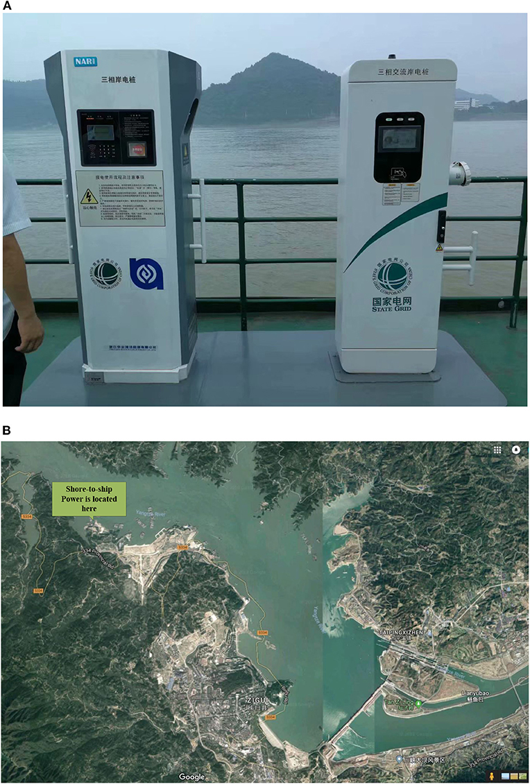
Figure 1. Shore-to-ship power charging piles (China State Grid Corporation) and a map of their location beside the Yangtze River. (A) Shore-to-ship power charging piles set up by China State Grid Corporation with no cable lifting device and connection system. (B) The shore-to-ship power charging piles are located on the upper left bank of the Yangtze River Three Gorges Dam.
Similarly, through on-site visiting and investigation, we found other shore-to-ship charging piles that are rarely used because a suitable Cable Lifting Device (CLD) is lacking. One example is shore-to-ship power charging piles built by China Three Gorges Power Corporation and located at the cruise terminal in the Three Gorges Dam area. An image of the piles and a map of their actual location can be found in Figure 2.
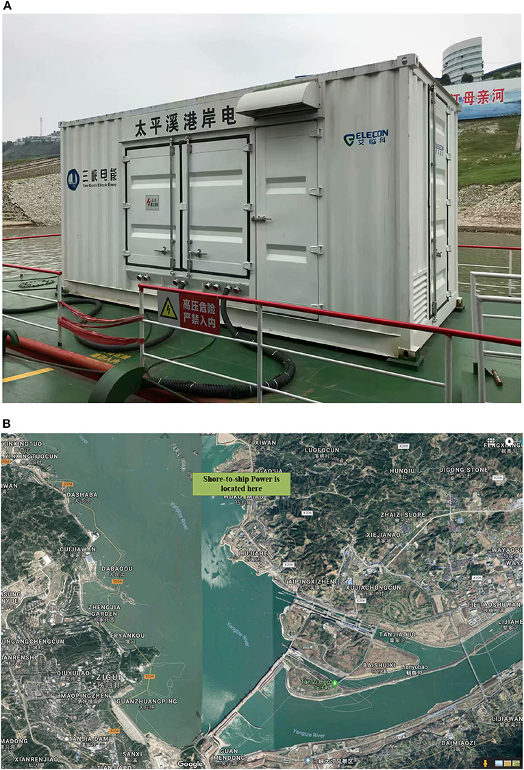
Figure 2. Shore-to-ship power charging piles (China Three Gorges Power Corporation) and a map of their location beside the Yangtze River. (A) Shore-to-ship power charging piles set up by China Three Gorges Power Corporation with no cable lifting device and connection system. (B) The shore-to-ship power charging piles are located on the upper right bank of the Yangtze River Three Gorges Dam.
Further, we found that shore-to-ship charging piles also lacked a suitable CLD in Jinkou Ro-Ro Terminal, Wuhan city, along the Yangtze River. These shore-to-ship power charging piles were built by the China Yangtze River Shipping Industry Research Center. An image of the piles and a map of their actual location are presented in Figure 3.
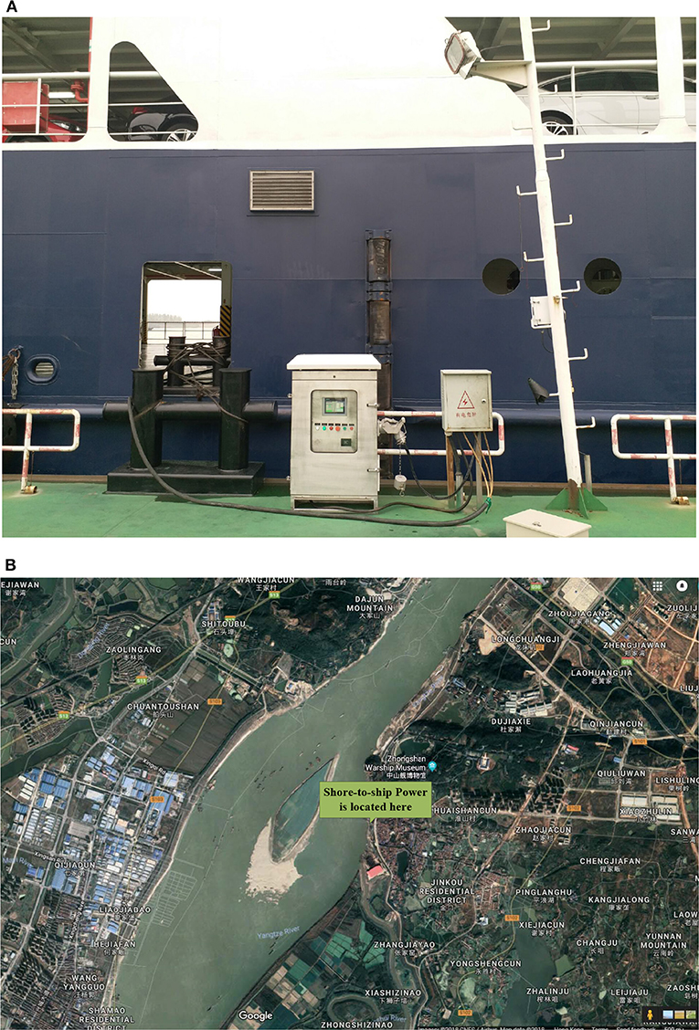
Figure 3. Shore-to-ship power charging piles (Yangtze River Shipping Industry Research Center) and a map of their location beside the Yangtze River. (A) Shore-to-ship power charging piles set up by the Yangtze River Shipping Industry Research Center with no cable lifting device and connection system. (B) The shore-to-ship power charging pile was located in Jinkou Ro-Ro Terminal beside the Yangtze River, Wuhan city.
Finally, we found that shore-to-ship charging piles also lacked a suitable CLD in Yangluo Port Container Terminal, Wuhan city. These shore-to-ship power charging piles were manufactured and produced by China Shanghai FEED POWER Power Supply Technology Co., Ltd., and are also located along the Yangtze River (Figure 4).
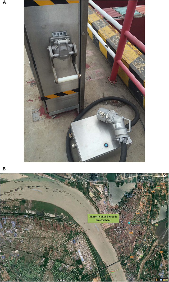
Figure 4. Shore-to-ship power charging piles (China Shanghai FEED POWER Power Supply Technology Co., Ltd.) and a map of their location beside the Yangtze River. (A) Shore-to-ship power charging piles set up by China Shanghai FEED POWER Power Supply Technology Co., Ltd. with no cable lifting device and connection system. (B) The shore-to-ship power charging piles are located in Yangluo Port Container Terminal, Wuhan city.
Cables used for shore-to-ship power connection systems are usually delivered from the shore to the ship by crane, and there are fewer dedicated cable lifting devices. After analyzing the disadvantages of delivering the cable by crane, this paper proposes a port cable lifting device to solve the problem of installing shore-to-ship power connection systems in inland ports.
When the cable is lifted by using a crane, the cable is hoisted manually. This cumbersome operation easily leads to excessive bending of the cable, which will hinder the normal use of the cable and reduce its life expectancy. The crane needs to be dispatched in advance. Its large size will affect the traffic in the port area. In addition, the diesel fuel normally used by cranes will cause pollution to the port environment. According to the actual needs of the port, a cable lifting device should meet the following requirements:
(i) Personnel need to operate cable lifts in safe places and avoid working at height. At the same time, personnel need to maintain a good field of vision so that it is easy to observe the working status of the cable lifting device.
(ii) In order to keep the cable lifting device working efficiently, manual lifting of the cable should be minimized.
(iii) Considering the height of the berthing ship, the position of berthing, and the position of the power receiving system onboard, the cable lifting device should be capable of adjusting the position of the cable within a certain range.
Based on the above requirements, the proposed cable lifting device consists of the following parts. The cable reel is used to tighten the cable by applying a constant torque to the cable. The slewing mechanism is placed on the ground and used to rotate the entire device. The lifting mechanism is used to adjust the height of the device. The extension mechanism is used to extend the cable, and the cable delivery mechanism is used to retract the cable.
The main part of the cable lifting device is placed on the platform that is on the top of the slewing mechanism. The outside of the rotary platform is a ring gear, and the motor is connected to a gear reducer to provide power. The slewing mechanism is equipped with travel switches, which are used to limit the rotation angle of the device. The lifting mechanism consists of a multi-level guide rail and a worm wheel screw hoist. The worm wheel screw hoist is fixed to the rotary platform, and the screw part is driven by the motor. The nut on the screw is connected to the second-level guide rail, and the lifting height of the second-level guide rail can be controlled by a worm wheel screw hoist. The guide rails at all levels are connected by sprockets and chains with their adjacent guide rails, except the first and the last guide rails. Take the second-level guide rail as an example. The top of the second-level guide rail is equipped with sprockets. A set of chains bypasses the sprocket above the second rail to connect the top of the first rail to the bottom of the third rail, as shown in Figure 5. When the second-level rail is moved up by the worm wheel screw hoist, the third-level rail will follow it. The second, third and fourth level rails are connected in the same way. Therefore, when the second-level rail is lifted, the third and fourth level rails will also be lifted by the same height relative to the lower-level rails. The height of the entire cable lifting device can be changed by controlling the rotation of the motor.
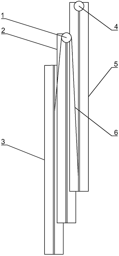
Figure 5. Chain connection of the guide rails (1: second sprocket, 2: second-level guide, 3: first level guide, 4: third-level sprocket, 5: third-level guide, 6: chain).
The extension mechanism is placed on the top of the lifting mechanism and consists of an extension frame, a support frame, a steel wire rope, a pulley, and a winch, as shown in Figure 6. One end of the extension frame is hinged with the platform on the top of the lifting mechanism and the other end is connected with a steel wire rope. The rope is bypassed above the pulley at the top of the support frame to connect the winch to the extension frame. Rollers are mounted on the top of the extension frame to ensure that the cable is not worn during lifting. When the extension mechanism is not in the working state, the extension frame is tilted to save space for storage. When the extension mechanism is in the working condition, the motor drives the winch to tighten the steel wire rope. The extension frame will be raised until it is perpendicular to the lifting mechanism. The cable can extend toward the docked side of the ship through the extension mechanism.
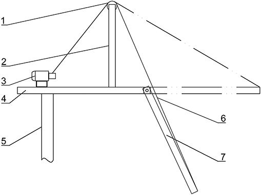
Figure 6. Extension mechanism (1: pulley, 2: support frame, 3: motor and winch, 4: top platform, 5: fourth-level rail, 6: steel wire rope, 7: extension frame).
The cable delivery mechanism consists of a first cable delivery device, a second cable delivery device, fairleads, and a reel, as shown in Figure 7. The first cable delivery device and the second cable delivery device are installed at the ground and extension frame ends, respectively, and control the retraction of the cable. The first cable delivery device is used to counteract the pre-load of the cable reel on the ground, and the second cable delivery device is used to power the cable lifting process. The cable is placed between the two pulleys of the cable delivery device, and there is a certain pre-load between the two pulleys. When the motor drives the pulley to rotate, the cable can be retracted. The fairlead consists of rollers and a roller bracket, and the two groups of rollers are placed vertically, as shown in Figure 8. There is a fairlead mounted on each level of the lifting mechanism. The space between the two rollers in one group of fairleads allows the cable to pass through without being squeezed, which is used to limit the movement of cables and reduce cable wear. The reel is located on the top of the last level of the lift mechanism to prevent damage to the cable due to a small bend radius. At the same time, friction between the cable and the cable lifting device is avoided and the additional load on the second cable delivery device is reduced.
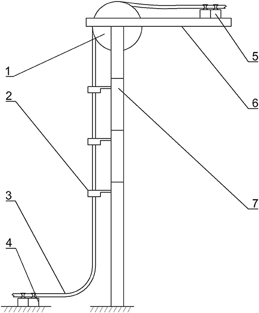
Figure 7. Cable delivery mechanism (1: reel, 2: fairleads, 3: cable, 4: the below cable delivery device, 5: the above cable delivery device, 6: top platform, 7: guide rails).
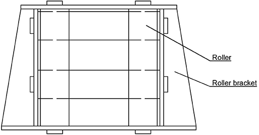
Figure 8. Fairlead.
The above-mentioned mechanisms include self-locking structures, such as a worm gear. Therefore, disconnecting the power supply to a motor can stop the corresponding mechanism in a specific position.
In this section, all of the mechanisms of the proposed cable lifting device use a motor as the power source. The parts containing a motor include the rotatory platform in the slewing mechanism, the worm wheel screw hoist in the lifting mechanism, a motor for powering the winch in the extension mechanism, and the first and second cable delivery devices in the cable delivery mechanism. When controlling the retraction of cable, it must be ensured that the first cable delivery device and the second cable delivery device transport the cable at the same speed. Since the first cable delivery device and the second cable delivery device can use the same structure to keep the rotational speeds of the two devices consistent, the cable delivery speed can be kept consistent. When controlling the height of the cable lifting device, it must be ensured that the speed of the cable delivery by the first cable delivery device is consistent with the lifting speed of the worm wheel screw hoist. Considering that the worm screw lift can maintain a stringent transmission ratio, it is feasible to control the cable lifting by maintaining the same speed on the motor of the two devices. According to the above analysis, the cable lifting device control circuit is shown in Figure 9.
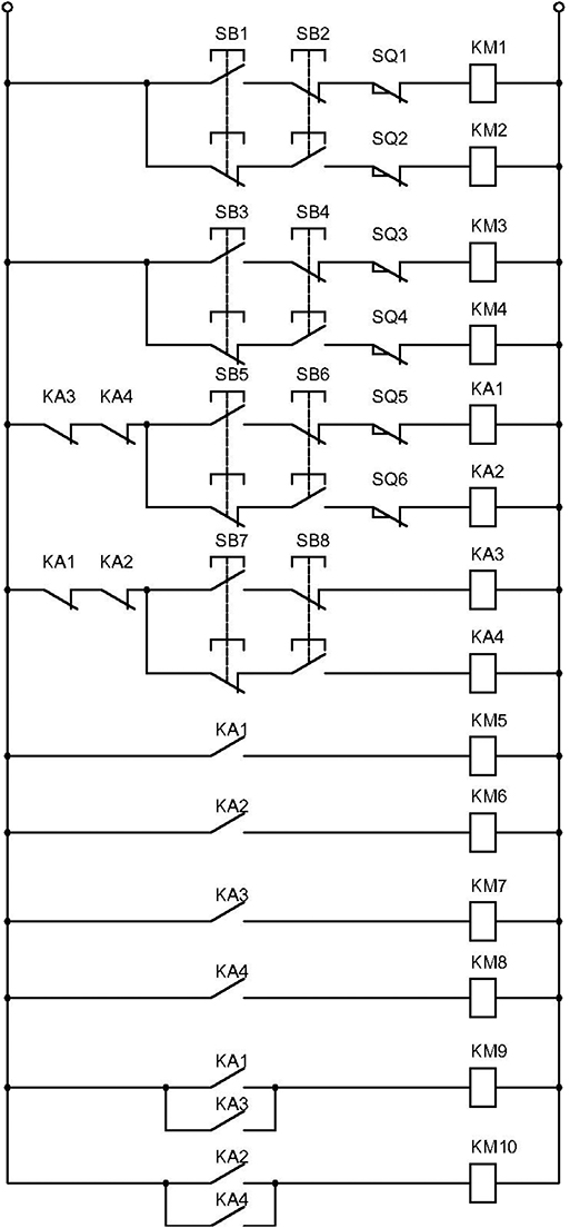
Figure 9. Cable lifting device control circuit.
Buttons SB1 and SB2 are the rotatory platform forward and reverse control buttons, respectively. The contactor coils, KM1 and KM2, respectively control the rotatory platform motor forward and reverse rotation. When the rotatory platform is rotated forward to the limit position, the travel switch SQ1 will be off to stop the platform rotation. When the rotatory platform is reverse-rotated to the limit position, the travel switch SQ2 will be off. Buttons SB1 and SB2 are interlocked to prevent the forward and reverse switches from closing at the same time, which may cause a short circuit. The components SB3, SB4, SQ3, SQ4, KM3, and KM4 are used to control the lifting and lowering of the extension mechanism, and its control method is the same as that of the rotatory platform. Buttons SB5 and SB6 are the cable lifting device lift up and down control buttons, respectively. The contactor coils KM5 and KM6, respectively control the lifting up and down of the lifting mechanism. The contactor coils KM9 and KM10, respectively control the forward and reverse rotation of the first cable delivery device. When the lifting mechanism lifts to the limit position, the travel switch SQ5 is off to stop the lifting mechanism. When the lifting mechanism goes down to the limit position, the travel switch SQ6 is off to stop the lifting mechanism. Buttons SB5 and SB6 are interlocked, for the same reason as previously described. The control circuit of the cable delivery mechanism is similar to that of the lifting mechanism. In order to prevent the cable delivery mechanism and the lifting mechanism from starting at the same time, the two mechanisms are interlocked through an intermediate relay.
According to the cable lifting device designed above, when the lifting device is used for lifting and retracting cables, two motors are required to operate cooperatively at a certain speed ratio. In the development of multi-motor control, there are two main ways to achieve collaborative control of the motors, namely mechanical and electrical. Mechanical means that mechanical devices are used to connect the motor to the production equipment, such as gears, chain belts, etc. Generally speaking, the mechanical device has a complicated structure, lacks flexibility, and has a limited working stroke, which is not suitable for the cable lifting device proposed in the current case. Therefore, this study uses a controller to control the output speed of each motor and reduce the motor speed deviance through the collaborative control strategy, so that the motors can run at a certain speed ratio.
The motors used in this study are all asynchronous motors. Compared with a DC motor, an asynchronous motor has a simple process structure, and its running stability is superior to that of a DC motor because it has no structure, such as a carbon brush. However, asynchronous motors are multivariable, strongly coupled, non-linear systems. Therefore, when developing a control strategy, a model of the motor should be transformed first.
The voltage equation of the three-phase winding of the motor is shown in Equation (1).
where uA, uB, uC represent the three-phase voltage of the motor stator, iA, iB, iC are the three-phase current of the motor stator, ua, ub, uc are the three-phase voltage of the motor rotor, ia, ib, ic are the three-phase current of the rotor, Rs, Rr are the resistances of the stator and the rotor winding, respectively, ΨA, ΨB, ΨC are the three-phase flux linkage of the stator of the motor, Ψa, Ψb, Ψc are the three-phase flux linkage of the rotor of the motor, and p = d/dt is a differential operator.
The three-phase winding flux linkage equation of the motor is shown in Equation (2).
In this equation, Lii(i = A, B, C, a, b, c) is the self-inductance of each winding, Lij(i, j = A, B, C, a, b, c and i ≠ j) is the mutual inductance of each winding, where Lij(i, j = A, B, C and i ≠ j) or Lij(i, j = a, b, c and i ≠ j) are constant, and the rest are parameters related to the rotor angle θ of the motor.
The torque equation of the motor is shown in Equation (3).
where Te is the electromagnetic torque, np is the number of pole pairs, TL is the load magnitude, J is the motor moment of inertia, and is the angular velocity.
It can be seen that the asynchronous motor model is very complicated, and it is very difficult to solve the above model. Therefore, the method of coordinate transformation is used to simplify the calculation of the model. First, the motor model is transformed into a two-phase stationary coordinate system using the Clarke transform. The transformation matrix is shown in Equation (4).
The transformation method used ensures that the magnitude of the current does not change after the transformation.
Then, use the Park transform to transform it into a two-phase rotating coordinate system. The transformation matrix used is as shown in Equation (5).
The simplified motor model obtained after coordinate transformation is shown in Equation (6).
where Lm is the mutual inductance between the stator and the rotor, Lr is the rotor self-inductance, Ψr is the rotor flux linkage, Tr = Lr/Rr is the rotor electromagnetic time constant, ωe is the stator electrical angular velocity, and ωsl is the slip angular velocity.
The above equation shows that the rotor flux linkage is determined by the current d-axis component isd in the synchronous rotating coordinate system. If the rotor flux linkage is kept constant, the electromagnetic torque of the motor can be controlled by adjusting the magnitude of the current q-axis component isq, thereby controlling the motor speed. A block diagram of the simplified model of the motor in the d−q coordinate system is shown in Figure 10.
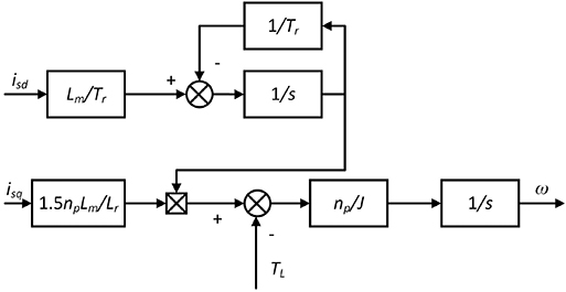
Figure 10. Simplified model of the motor.
According to the above analysis, the control strategy of a single asynchronous motor is shown in Figure 11. In this control strategy, the rotor flux linkage remains unchanged, so the current d-axis component reference value is constant. The electromagnetic torque is obtained by the PI controller and is used to control the motor speed. The actual rotor flux ψr can be directly obtained from the d-axis component of the current. The current q-axis component reference value can be obtained from the actual rotor flux ψr and the electromagnetic torque . The obtained current reference value is input to the pulse generator after the coordinate transformation, and the current reference value is compared with the actual current value to control the motor current. The above control strategy involves the calculation of the rotation angle of the Park transformation. The rotation angle can be obtained by integrating the electrical angular velocity of the stator. The calculation process of the electrical angular velocity of the stator has been given in the foregoing.
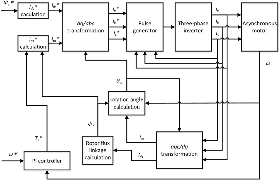
Figure 11. Control strategy for a single motor.
It is sometimes necessary to ensure that two different mechanisms operate at a certain speed ratio in the proposed cable lifting device. Therefore, the cross-coupling control method is adopted to ensure that the two motors work with a stable speed ratio, and the control mode is as shown in Figure 12. The deviance in speed between the two motors is processed by the PID controller and output to the speed controllers of the two motors. The speed of the two motors is affected by the actual speed and speed input error and is also affected by the deviance in speed between the two motors. This type of control ensures that the speed of the other motor changes as the speed of one motor is disturbed.
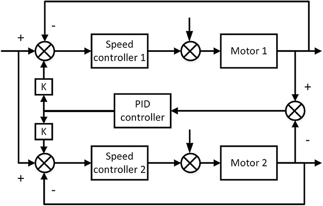
Figure 12. Control strategy for multiple motors.
Before the simulation of the proposed collaborative control strategy, the control strategy of a single motor needs to be verified. The simulation results are shown in Figure 13.
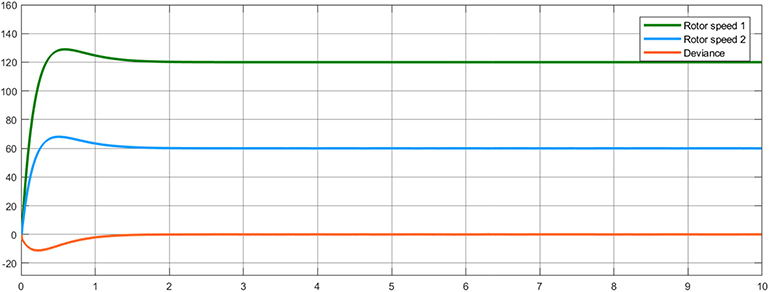
Figure 13. Simulation results of model without collaborative control.
The simulation results show the change of the speed deviance and of the two motors over the course of 10 s. Here, the target speed ratio of motor 1 and motor 2 is 2:1, so the deviance is the difference between the speed of motor 1 and twice the speed of motor 2. The simulation results show that it takes about 2 s from start-up for the two motors to stabilize at the target speed. For a single motor, this control strategy effectively controls the speed of the motor. However, before the speed of the motor stabilizes, the deviance between the speeds of the two motors reaches a large value, and it is necessary to add a collaborative control strategy.
Considering that the load changes during the actual operation of the motor, a step signal is added to the load input of the two motors at 4 s. The two step signals are the same size and in opposite directions. At the same time, in order to facilitate the comparison of the collaborative control methods, a collaborative control model that does not include a PID controller is added on the basis of the above two models. The simulation results of the three models are shown in Figure 14.
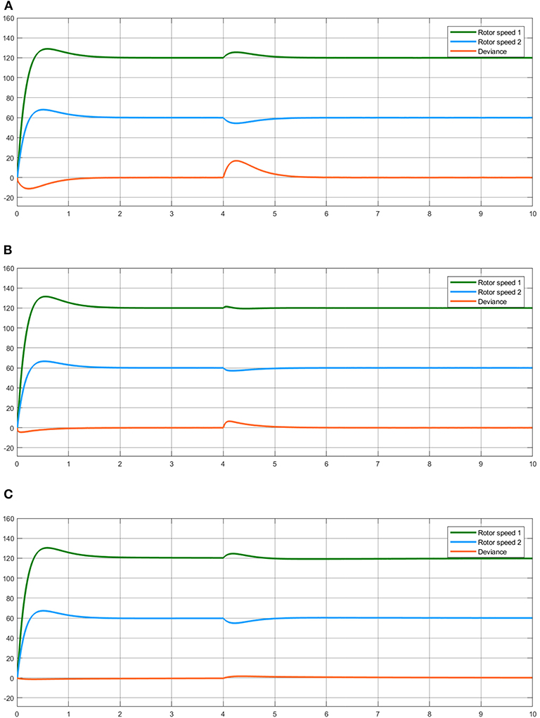
Figure 14. Simulation results for when the load changes. (A) Control method without collaborative control. (B) Collaborative control method without PID controller. (C) Collaborative control method including PID controller.
In the control method without collaborative control, the speed of the two motors stabilizes within about 2 s of starting. At 4 s, the load of the two motors changes. The speed of motor 1 increases significantly and then decreases, and change in motor 2 is opposite to that in motor 1. About 1.5 s after the load change, the speed of the two motors returns to a stable value. From the deviance curve of the two motors, it can be seen that both motors produce a large speed deviance at start-up and load change.
In the collaborative control method without a PID controller, the speed change trend of the two motors is similar to in the control method without collaborative control, but the deviation from the steady speed is significantly smaller than in the former. At the same time, the speed deviance between the two motors at start-up and load change is also less than that without collaborative control.
In the collaborative control method including a PID controller, the speeds of the two motors also fluctuate when the load changes. The variation range is smaller than in the control method without collaborative control but is larger than in the collaborative control method without a PID controller. It can be seen from the speed deviance curve of the two motors that the collaborative control method including a PID controller has the smallest speed deviance. Therefore, this control method is superior to the other control methods described above.
Ports are an important driver of world economic growth and are also major sources of pollution and energy-consuming units. The proposed port cable lifting device for shore-to-ship power systems has the characteristics of small size, convenient operation, and so on. The simulation results show that the speed control strategy used can enable the motors to reach the required speed in a short time. The collaborative control strategy ensures that the speed ratio of the two motors during operation will not change drastically due to load changes. It can provide a better solution for the cable lifting problems of shore-to-ship power systems in inland ports and provides a solution to promote the use of green and lightweight port shore power systems. In future research, the control strategy of the lifting device will be further studied to further reduce the deviance in rotation speed.
The raw data supporting the conclusions of this article will be made available by the authors, without undue reservation, to any qualified researcher.
All authors listed have made a substantial, direct and intellectual contribution to the work, and approved it for publication.
This work was supported by the Fundamental Research Funds for the Central Universities (WUT: 173118001), the Open Project Program of the National Engineering Research Center for Water Transport Safety (No. A2019006), and the Open Project Program of the State Key Laboratory of Ocean Engineering (No. 1812).
The authors declare that the research was conducted in the absence of any commercial or financial relationships that could be construed as a potential conflict of interest.
Adamo, F., Andria, G., Cavone, G., Capua, C. D., Lanzolla, A. M. L., Morello, R., et al. (2014). Estimation of ship emissions in the port of taranto. Measurement 47, 982–988. doi: 10.1016/j.measurement.2013.09.012
Ćelić, J., Valčić, S., and Bistrović, M. (2014). “Air pollution from cruise ships,” in Proceedings ELMAR-2014 (Zadar), 1–4.
Coppola, T., Fantauzzi, M., Miranda, S., and Quaranta, F. (2016). “Cost/benefit analysis of alternative systems for feeding electric energy to ships in port from ashore,” in 2016 AEIT International Annual Conference (AEIT) (Capri), 1–7.
Hou, J. (2017). “Operation strategy of shore to ship power based on improved droop control,” in 2017 IEEE Transportation Electrification Conference and Expo, Asia-Pacific (ITEC Asia-Pacific) (Harbin), 1–6.
Jayasinghe, S. G., Al-Falahi, M., Enshaei, H., Fernando, N., and Tashakori, A. (2016). “Floating power platforms for mobile cold-ironing,” in 2016 IEEE 2nd Annual Southern Power Electronics Conference (SPEC) (Auckland), 1–5.
Kegalj, I., and Traven, L. (2018). Possibility of implementation and environmental benefits of high-voltage power supply in developing countries, example of Croatia. Int. J. Environ. Sci. Technol. 15, 1343–1346. doi: 10.1007/s13762-017-1499-4
Kumar, J., Palizban, O., and Kauhaniemi, K. (2017). “Designing and analysis of innovative solutions for harbour area smart grid,” in 2017 IEEE Manchester PowerTech (Manchester, UK), 1–6.
Pan, L., Shao, J., and Xu, C. (2018). “Control research on electrical system of intelligent low voltage shore side electric pile for river port,” in 2018 37th Chinese Control Conference (CCC) (Wuhan), 8347–8352.
Parise, G., Parise, L., Chavdarian, P. B., Sabatini, S., and Su, C. (2015). “The TN-island system for cold ironing,” in 2015 IEEE Industry Applications Society Annual Meeting (Addison, TX), 1–6.
Paul, D., and Haddadian, V. (2011). Transient overvoltage protection of shore-to-ship power supply system. IEEE Trans. Ind. Appl. 47, 1193–1200. doi: 10.1109/TIA.2011.2125772
Paul, D., Haddadian, V., Chavdarian, B., and Peterson, K. (2017). “Low-voltage shore connection power systems,” in 2017 IEEE/IAS 53rd Industrial and Commercial Power Systems Technical Conference (I CPS) (Niagara Falls, ON), 1–6.
Paul, D., Haddadian, V., Chavdarian, B., and Peterson, K. (2018). Low-voltage shore connection power systems: optional designs and a safety loop circuit. IEEE Ind. Appl. Mag. 24, 62–68. doi: 10.1109/MIAS.2017.2740448
Paul, D., Peterson, K., and Chavdarian, P. R. (2012). “Cold ironing power system design and electrical safety,” in 2012 Petroleum and Chemical Industry Conference (PCIC) (Chicago, IL), 1–9.
Prenc, R., Vučetić, D., and Cuculić, A. (2018). High voltage shore connection in croatia: network configurations and formation of the connection point to the utility power grid. Electric Power Syst. Res. 157, 106–117. doi: 10.1016/j.epsr.2017.12.011
Prousalidis, J., Antonopoulos, G., Patsios, C., Greig, A., and Bucknall, R. (2014). “Green shipping in emission controlled areas: combining smart grids and cold ironing,” in 2014 International Conference on Electrical Machines (ICEM) (Berlin), 2299–2305.
Sciberras, E. A., Zahawi, B., and Atkinson, D. J. (2015). Electrical characteristics of cold ironing energy supply for berthed ships. Transport. Res. D Transport Environ. 39, 31–43. doi: 10.1016/j.trd.2015.05.007
Keywords: shore-to-ship power connection system, collaborative control, cable lifting device (CLD), inland port, mathematical model, PID controller
Citation: Pan L and Shao J (2020) A Novel Intelligent Shore-to-Ship Power Supply System Using Collaborative Motor Control. Front. Mech. Eng. 5:70. doi: 10.3389/fmech.2019.00070
Received: 27 March 2019; Accepted: 19 December 2019;
Published: 14 February 2020.
Edited by:
Marco Guerrieri, University of Trento, ItalyReviewed by:
Ping Liu, Jiangsu University of Science and Technology, ChinaCopyright © 2020 Pan and Shao. This is an open-access article distributed under the terms of the Creative Commons Attribution License (CC BY). The use, distribution or reproduction in other forums is permitted, provided the original author(s) and the copyright owner(s) are credited and that the original publication in this journal is cited, in accordance with accepted academic practice. No use, distribution or reproduction is permitted which does not comply with these terms.
*Correspondence: Lin Pan, bGlucGFuZHJAMTYzLmNvbQ==
Disclaimer: All claims expressed in this article are solely those of the authors and do not necessarily represent those of their affiliated organizations, or those of the publisher, the editors and the reviewers. Any product that may be evaluated in this article or claim that may be made by its manufacturer is not guaranteed or endorsed by the publisher.
Research integrity at Frontiers
Learn more about the work of our research integrity team to safeguard the quality of each article we publish.