
94% of researchers rate our articles as excellent or good
Learn more about the work of our research integrity team to safeguard the quality of each article we publish.
Find out more
ORIGINAL RESEARCH article
Front. Water, 03 July 2024
Sec. Water and Hydrocomplexity
Volume 6 - 2024 | https://doi.org/10.3389/frwa.2024.1357976
 Yiu-Kuen Leung1
 Ka Wai Eric Cheng2*
Although environmental groups have declaimed the application of greywater to alleviate water consumption, the progress of condensed water implementation for high-rise buildings was still sluggish. As greywater demands wastewater treatment before any application, the novelty of this study was to demonstrate the direct use of condensed water in an existing cooling water system without wastewater treatment. Considering there is barely any practical case study research to unveil the water-energy nexus in reclaiming condensed water for evaporative cooling tower systems, this research has signified that condensed water is a simple and low-budget application for water conservation and energy saving. Given that the condensed water possesses an intrinsic impurity-free property, the water-saving potentials have been amplified to the most tolerable total dissolved solids (TDS) of system water. Furthermore, it is beneficial that water quality control ameliorated the operating working conditions, the system performances were improved, and then less power was consumed. By getting rid of the wastewater treatment, consolidating the feasibility of practical direct-use application, and its sustainability for water and energy saving, this research may revive the attention of green building claimers to expedite its implementation and tie in the green building design. The condensed water derived from the electric ventilation system was reclaimed as an alternative water source for cooling without extra power consumption, which was ideal for concentration dilution and beneficial to descaling. An evaporative cooling system consumes tons of water, and the water losses are necessarily compensated by fresh water; this process occurs gradually over time and progressively escalates the TDS with time, which evocates water scale formations. Although the bleed-off (BO) that discharges the impurity-laden system water effectively lowers the TDS, it is not a water conservation measure, and the chemical effluent poses environmental hazards. The higher cycles of concentration (CoC) reduce the frequency of BO and sustain the full efficacy of antiscaling chemicals. Whenever water scales appear as a resistance of heat transfer deposit on the heat exchangers, the heat management capability is diminished and energy efficiency drops. The water and energy saving enhancement method was accomplished by reclaiming the condensed water and setting higher CoC.
Notwithstanding the BEAM Plus for present construction (HKGBC, 2010) and new construction (HKGBC, 2012) suggests possible usages of recycled greywater (Filali et al., 2022), which is one of the water conservation assessments for a sustainable building, are predominantly adopted for plant irrigation and flushing (Khajvand et al., 2022), the progress of the implementation of condensed water into practice is sluggish (You et al., 2017), and one of the reasons is the relatively small amount of water that can be reclaimed from condensation. Especially for high-rise buildings, the condensed water is seldom used for water cooling tower systems due to the topographical challenges it presents, which would require additional energy and incur extra costs to lift the water to achieve a high operation point. The amount of condensed water depends on the apparatus dew point, moisture contents of air, and the efficiency of the condensation capture system. In high-rise buildings, the condensed water collected from air conditioning units is typically minimal compared to the total water demand of the building. The other reason is that the condensed water—collectively named greywater—hinders the progress of condensed water reclaiming because, technically, the greywater or wastewater produced from daily activities (Engstler et al., 2022), such as domestic use, industrial processes, or agricultural practices, is so heavily polluted that it needs to be treated with a water treatment plant in which sedimentations and biological and chemical treatments are carried out to ensure the safe reuse for irrigations or flushing. Intrinsically, condensed water is as close to pure water resources; it can directly dilute the impurity-infused refreshing water of an evaporative cooling tower.
This study aims to extricate the interwoven nexus of water and energy and fill the gap of reclaiming condensed water that enhances water and energy saving to evocate the codification for green buildings and system design. The reuse of condensation water irrigation for water recycling has been documented (Siam et al., 2019). Although the yield of condensed water varies and is subject to unpredictable weather (Fu et al., 2021), it demotivates its implementation by the cooling tower operators, is a sustainable exercise, and is a conservation of the capital and environment. The study presented demonstrates the practical condensed water reclaimed by the modifications on the condensing drain pipe to improve the existing water-captured system. The next objectives demonstrated the assessments and arrangement for realizing the possible water reclaiming and justifying the results with the actual measurement against theoretical examination. The last objective demonstrated the complicated interdisciplinary relationships between water and power saving through the improvement of power-intensive equipment performance that was obtained after using the reclaimed condensed water in the ventilation system. The proposed study contributed to the expedition of using intrinsic good-quality condensed water that should not have been named greywater, which is notorious for the need for a wastewater treatment plant before any applications.
This case study is for an existing high-rise complex building in which the main condensate downpipes were needed to modify and redirect the condensed water flow toward the settlement tanks where the floating pipe rust and other precipitations were preliminarily screened off, simple disinfection was carried out, and then the condensed water directly flows to the cooling towers by gravity.
The limitation of the spatial requirement for modifications on the existing pipework was encountered that did not allow all the condensed water collection from the air handling units (AHU) in which much more condensed water could have been reclaimed because those AHUs were treating the fresh incoming outdoor air of high humidity.
The antiscalant polymers (ASP) that decrease the precipitations of calcium carbonates (i.e., calcite, CaCO3) (Ismail et al., 2019), which are the major water scales, are popularly dosed in the system water; the nucleation and crystalline growth are hindered so that the solubility of calcite is improved, therefore, allowing high CoC. However, the higher CoC comes with higher CaCO3 raises, and the pH makes the water more alkaline. High alkalinity and high polymer concentration are not desirable for chemical efficacies that could be moderated with acidification, which ameliorates the polymer absorption plateau by injecting a stoichiometric amount of acid to protonate the calcite solution and resuscitate solubility. The proposed condensed water scheme utilizes soft water that facilitates the most suitable water treatment with minimal dosing of chemicals and polymers for scale abatement (Neveux et al., 2016).
When the water is evaporated from an evaporative cooling tower, the dissolved impurities such as minerals in the liquid phase remain in the system and the water accumulates. Whether the solubility is exceeded, the impurity precipitation occurrence makes the water turbidity high, which proliferates with scale depositions across the entire surfaces making contact with the water, particularly at high temperatures (Judd, 2003). The water hardness and alkalinity result from insoluble calcium carbonate in the process of carbon dioxide, which is being stripped from bicarbonates during water heating. The chemical reaction of calcite formation is:
The chemical treatment is the most affordable antiscaling approach with substoichiometric amounts of scale inhibitor being ample to create protective layers over the nucleation sites or microflows that connect the proliferation of crystalline growth by surface modifications.
Once the water scale is formed and deposited onto the surface of the heat exchanger, the heat transfer between water and air or water and refrigerant is greatly reduced by the layers of these heat barriers that are progressively growing with time, jeopardizing the performance of condensers and cooling towers.
An evaporation system releases heat waste to the ambient air, inevitably exposing it to the foreign particulates that contaminate the water and make the open-loop condenser water circuitry vulnerable to scale formations and fouling.
The decrease in cooling efficiencies causes the heat exchangers to demand more energy to compensate for the losses of the cooling effect, which are required for normal system operations. The inefficiency of cooling towers caused by the water scale deposited on the baffles raises the cooling tower leaving water temperature or the entering condenser water temperature (ECWT), whereas the efficiency drop of condensers diminished heat transfer concerning water, and refrigerant gas attributed to the condenser scale deposition raises the leaving condenser water temperature (LCWT). The difference between LCWT and condensing refrigerant temperature (CRT) termed as condenser approach temperature (CAT) reveals the severity of the heat barrier formed on the tube surfaces of the condenser. For the power consumption assessments, the CRT referred to, instead of CAT for the sake of the Mollier diagram, always indicates the properties of refrigerant inclusive of the refrigerant phase change stages and the corresponding enthalpies that are adopted for determining the coefficient of performance (COP) of the condensers and power requirements.
The subcooling and superheating of refrigerant in the vapor compression refrigeration cycle (VCRC) could improve the COP by arranging the refrigerant flow and utilizing the remaining cooling and heating energy. One of the subcooling arrangements is the liquid-suction heat exchanger (LSHX) subcooling, which has been commercially adopted and performs 9% moderate COP improvement. In the LSHX, the heat exchange happens between the liquid refrigerant, which is further cooled down (subcooled) before entering the expansion device, and the vapor refrigerant, which is further heated up (superheated) before entering the compressor as present in Figure 1A (Sumeru et al., 2019).
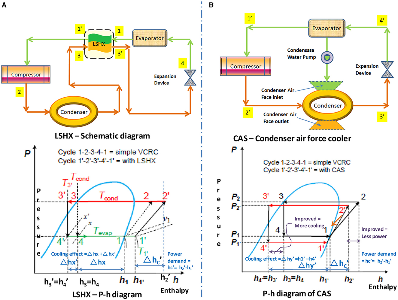
Figure 1. Schematic and p-h diagram for (A) LSHX and (B) CAS.
The subcooling and superheat of LSHX improve the COP and are demonstrated as Equation (1) below:
where, Δhx = h1 – h4; Δhx′= h4 – ; Δhc′= –
The merits of using condensed water are exhibited in the condensate assistant subcooling (CAS) system in which the condensed water is utilized to lower down operation temperature for the condenser air face and compressor discharge. The condensed water harvested from the evaporator is commonly of lower temperature, such as 4.5°C, and is sprayed into the air face of condenser coils (e.g., 29°C) and/or compressor discharges (e.g., 58°C), which are then brought to a lower temperature by evaporative cooling. Due to the significant temperature difference between the condensers and compressors, condensed water has a strong cooling capacity that facilitates subcooling of the condenser from T3 to T3′ and compressor discharge from T2 to T2′, as illustrated in Figure 1B. Although the electric pump for water spray is involved in the system, the power consumption is relatively insignificant to that of the compressor. This makes condensate assistant subcooling (CAS) offer a greater COP improvement than that of LSHX subcooling, which is a promising energy-saving measure (Khajvand et al., 2022).
The subcooling of CAS improves the COP is demonstrated as Equation (2) below:
where, Δhy′= - ; Δhc′= – .
The modification of the normal drain and downpipes is the first step for the re-channel of the condensation water. Also, the measurement units for water were necessary to provide for recording and control, measure and monitor the water quality, and the actual water and power consumptions that were crucial to all the following assessments, verifications, and analyses, as illustrated below. The actual measurements for the water sides are summarized and shown in Figure 2.
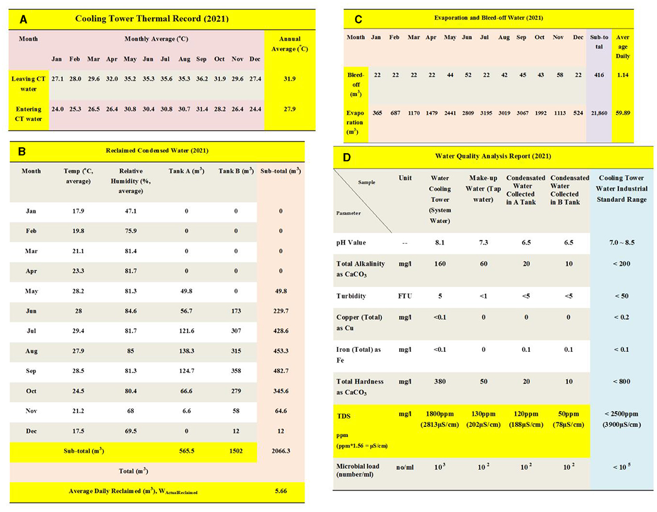
Figure 2. Summary of the actual measurement for (A) Cooling tower operator water temperature; (B) Reclaimed condensed water; (C) Evaporation and bleed-off water; (D) Water quality analysis report.
All possible condensed water could be first collected and stored in storage tanks before sending it to the cooling towers. The collection can be obtained from fan coil condensation pipes and any cool surface. The water examination reports for the reclaimed water in the condensation unit, fresh makeup water, and BO water are essentially carried out for the CoC work complying with industrial norms. The additional water meters were also installed for measuring individual water consumptions, including water reclaimed, BO, make-up, and evaporation. These data will enable the control development, interweaving interactions, and performance, to facilitate the reuse of the condensed water and develop the energy-saving scheme.
To further enhance the usage of the reclaimed water due to the condensation water and maximum tolerance parameter of CoC, the existing chemical dosage system was kept intact without changing the amount of dosage and dosing frequency. Moreover, the TDS was supervised by the water quality controller, which monitored the real-time electric resistivity of plant water and controlled the BO valve, which would discharge the impurity-laden system water as needed.
To improve the chiller performance such that the effective descaling ameliorated the heat exchanger conversion rate, the temperature management for the towers and condenser is controlled effectively so that operational temperature for refrigerant helps the performance of the chiller in terms of the coefficient of performance (COP) efficiently. Figure 3A provides a schematic representation of the system for harvesting reclaimed condensed water, controlling water quality, and measuring water usage. In addition, Figure 3B showcases the electrical conductivity is lowered by bleed-off.
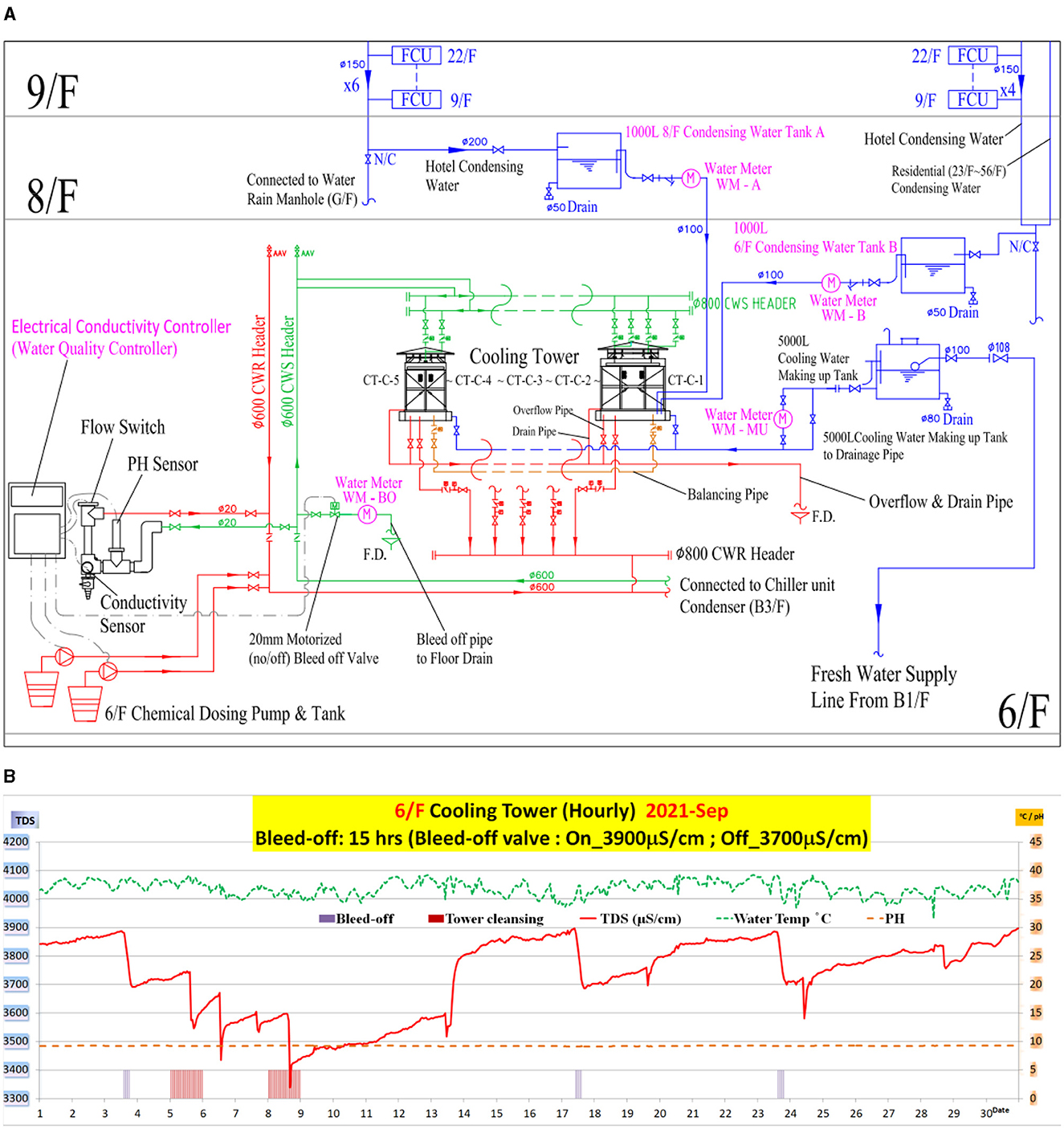
Figure 3. (A) Schematic for condensed water reclaimed for cooling water; (B) The typical graph for bleed-off (BO) and electrical conductivity.
Figure 2A has recorded the average temperature and range of the CT, and they can be used to examine the water requirement together with the manufacturer's specification.
The temperature range of the tower in average TACT is the variance against the water in TCTin and the water-out temperature of the cooling tower TCTout. Given that TCTin is 31.9C and TCTout is 27.9°C, it follows that:
It is noted that the cooling load that was changing from full load to part load in a year that corresponded to the annual range temperature of CT was 4°C.
Concerning the cooling tower data (SPX, 2022), the cooling tower with 4°C range temperature of CT, which was served by the cooling water pump of 648 m3/h water flow volume, required 4.5 m3/h new make-up water for cooling the heat loads by evaporation, which was the water requirement or consumptions of the cooling water system. According to the BO Equation (5) below, the BO is decreased to the lowest point during high CoC, which will result in the evaporation speed almost equal to the make-up water rate.
The analytical utilization of the make-up water is:
The water evaporated, and the water was discharged inclusive of BO, and the drift losses needed to be compensated by the new make-up water. The CoC is determined by the TDS, BOV, and the drift, as formulated by the BO Equation (3) (HKEMSD, 2016).
where,
BOV – Bleed-off volume
BL – The rate of bleed-off (BO) (L/s);
Ev – The evaporation (L/s);
CoC – The cycles of concentration;
D – The rate of design of drift losses (L/s)
The upper limit of CoC for the system water is calculated by Equation (4):
where, TDSB = TDS of BO water (ppm) and TDSM = TDS of make-up water (ppm). Using the data in Figure 2D, the following parameters are used.
The TDS of BOV = 2,500 ppm
The TDS of make-up water = 130 ppm
The rate of evaporation, E = EAE = 59.89 m3/day
Referring to the manufacturer's parameter (SPX, 2022), it can be found that for the present setup, the water losses of drift, D, is only 0.0005%. As D is very low it can be eliminated from (3) to form Equation (5):
The overall volume of make-up water and hard BOV is the water consumption. The percentage of the hard BO to the overall capacity at CoC 19.2 is evaluated:
where, EAE = 59.89 m3/day (as seen in Figure 2C)
By use of the BO Equation (5), the BO rate is 5.2% against the flow rate at COC 19.2. Then, based on the assumed make-up water of 4.5 m3/h at CoC of 19.2 was demanding 5.2% BO as:
With BO volume subtracted from make-up water, it is the analytical evaporation EALE :
It can be seen that EALE =102.4m3/day, which accounts for over 94% of the makeup water. This is to provide the top-up for the shortage of water at over CoC 19.2.
We have assigned two water storage namely A and B used to collect the water as shown in Figure 2B in which the floating rust was screened off, the precipitates were settled down at the bottom of the tanks, and then the clear condensed water was reclaimed as supplement water for make-up water that was metered to the amount of 2,066.3 m3 in 2021.
Then, the condensed water volume reclaimed per day:
Water losses include the evaporation and BO. The purpose is to use the makeup water, and they are separately metered to the amount as recorded in Figure 2C.
The rate of BO, BAAB = 1.14 m3/day
The rate of evaporation, EAE = 59.89 m3/day
The measurement of the make-up water MAM has been conducted using BAAB and the EAE, and can be expressed as:
The percentage of such water for makeup MAM to the calculated top-up water MALM for the year of 2021 under the study is simply expressed as:
The difference from unity is the saving of make-up water that of course incorporates with the reclaimed condensed water:
The assessment of the water quality for the fresh make-up water using the reused condensed water has been conducted and evaluated with the established water cooling in the tower, as depicted in Figure 2D.
The reused water from the condensation was gathered from discrete locates and diverse tube paths; the water from the tanks under test was found different in volume as per Figure 2B and in TDS as per Figure 2D.
The reclaimed condensed water of Tanks A and B in 2021 is also tabulated in Table 1. The TDS of condensed water, TDSTAB, was averaged to be:
The received condensed water had fairly low TDS that is reclaimed as the supplements to make-up water effectively dilute the impurity-laden water.
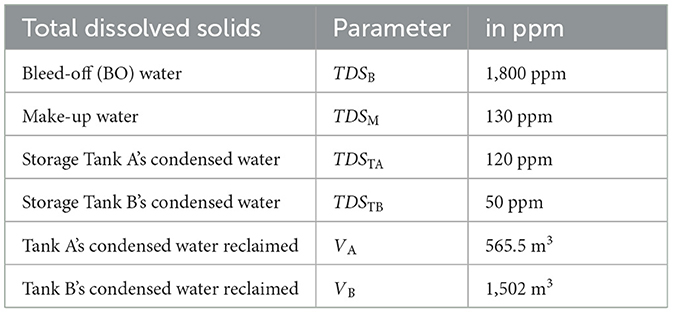
Table 1. The Total Dissolved Solids of various types of water in the system.
The ratio of the TDS in the freshwater to the TDS existed in the reclaimed water is called the augmented dilution, DAG
It can be seen that the volume of reclaimed water with a TDS of 69.2 ppm had been increased by a factor of 1.88, which was equivalent to a TDS of 130 ppm dilution in freshwater. The counterpart volume of new make-up water, MD is:
The RAR is recorded from Figure 2B as 5.66 m3/day.
The BO performance is monitored by the electrical resistance (ER) regulator. The measurement of collection is found in Figure 2C. With now under the auto BO, , as referred to in Figure 2C, the saving of volume for the BO is then:
The proportion in authentic auto BO capacity against astute hard BO capacity is simply:
The saving in BO is different from the unity:
The total equivalent water saving, MEQBDS that comes from minimal auto BO at high CoC 19.2 and the augmented dilution of low TDS of condensed water is:
The percentage of total equivalent water saving, MEQBDS, to the total make-up water consumptions which are the evaporation, EAE, and auto BO, BAAB, can be expressed/ as:
The water saving for make-up water is 25%, which resulted from reclaiming the condensed water, augmented dilution, and reduction of BO at CoC of 19.2.
Similarly, the percentage of the augmented dilution saving to the total make-up water can be expressed as:
The water saving for the make-up water is 17.4%, which resulted from reclaiming the condensation and augmented thinner effect. It is noted that the volume of reclaimed condensed water should vary with the ever-changing cooling loads and erratic atmospheric situations, such as humidity and temperature. The reduction of BO, BRD, was 4.476 m3/day, which was obtained by high COC, and the real-time electric resistivity control of TDS, which was performed by the EC controller and auto BO control system. The absence of intrinsic impurities in condensed water enables a reduction in BO, extending the residence time of chemical reagents and enhancing their anti-fouling efficacy.
Whenever water scale deposits on the heat exchanger surface where the heat transfer cannot effectively be performed, the performance of the chiller unit will be reduced because of demands for more power energy to achieve the same cooling effects. An evaporative cooling tower water circuitry is an open-type system encountering with detrimental outdoor environment under which the foreign particulates easily invade the system water and are more vulnerable to water scale deposit and fouling. Once the water scale is formed on the tube's outer contact surfaces, the condensing refrigerant temperature (CRT) cannot effectively be brought down by the cooling tower water leading to a higher condenser approach temperature (CAT). CAT is the temperature gradient between CRT and the exit condensing water temperature (LCWT). The condensing water is flowing to the evaporative cooling tower to dissipate the heat into open air. In the wake of less heat being absorbed by the cooling water, the CRT rises from T3 to T3′ (Pottker and Hrnjak, 2014; Coker, 2015a,b).
The theoretical COP is demonstrated as Equation (6) below:
Then, the refrigerant effect h1− h4 reduces to h1− , and
the compressor work h1− h2 increases to h1−
Since the condenser refrigerant is working at a higher temperature of T3′ and the compressor needs more input power at T2′, the COP is then decreased as shown in Figure 4A.
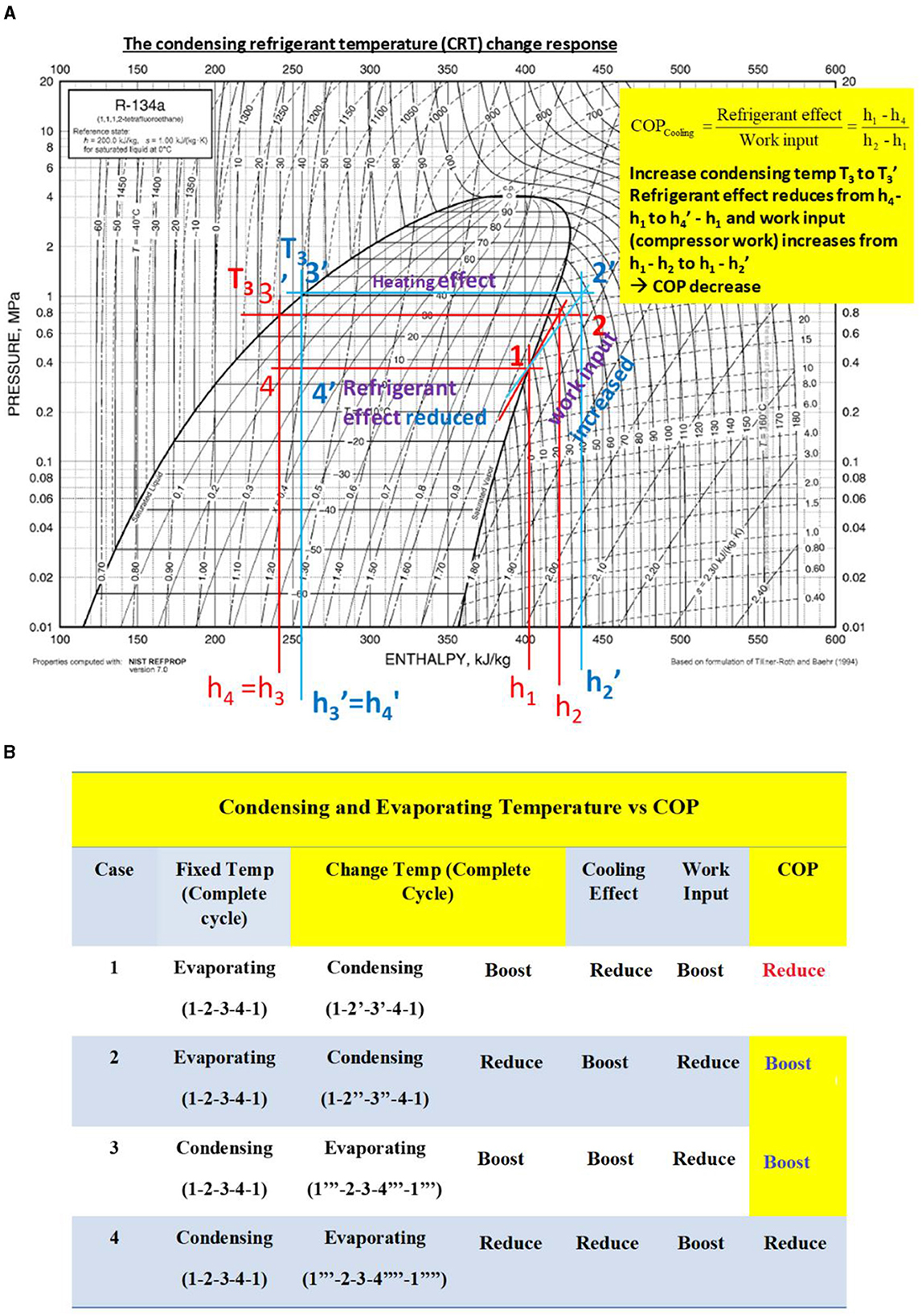
Figure 4. (A) The variation of condensing refrigerant thermal behavior plotted on a Mollier (p–h) Chart; (B) Condensing and evaporating temperature vs. COP.
Figure 4B shows the change in refrigerant temperature of condensers, and the evaporators affect the value of COPs.
Case 1 is the increase of CRT, which results from the inefficiency of heat transfer for the heat exchangers because, for instance, the cooling water flow is hindered or the water scale is deposited onto the surfaces of condenser tubes.
Case 2 is the decrease in CRT, which results from the improvement of heat transfer of the heat exchanger because, for instance, the cooling water flow is fluent or proper descaling and cleansing for the condenser tube surfaces occurs.
Case 3 is the increase in evaporating refrigerant temperature (ERT), which resulted from the improvement of absorption from the heat sources due to, for instance, proper descaling and cleansing for the evaporator tube surfaces.
Case 4 is the decrease in ERT, which results from the inefficiency of heat absorption from the heat sources due to, for instance, the heat flow being hindered or water scale being deposited onto the surfaces of evaporator tubes.
The work input or power is required by the compressor as calculated by Equation (7) as below:
where RT is the refrigerant tonnage of the chiller unit
Likewise, the required work input was evaluated for the four cases, as tabulated in Figure 5.

Figure 5. Work input and COP vs. CRT and ERT.
For Case 2, the CRT is improved (i.e., cooled down), which offers 4.2% per °C decrease in work input due to 5.6% per °C improvement in COP.
For Case 3, the ERT is improved (i.e., heated up), which offers 2.9% per °C decrease in work input due to 3.3% per °C improvement in COP.
It detected that the energy saving from the improvement of CRT is greater than that of ERT. Therefore, the reclaim of condensed water as a measure of CRT improvement is sensible and hits the nail on the head.
That makes sense to allow a large fouling factor Fc for refrigerant condensers (i.e., 0.00025 hr·ft2/Btu) with the consideration that the open-loop circulating water for an evaporative cooling system is subject to the pollution of external contamination from time to time, whereas a lower Fc is implemented for the evaporator enclosed chilled water path that is free from the invasion of extraneous particulates. The AHRI (AHRI, 1997) illustrated that a 0.00025 h·ft2/Btu fouling factor would degrade the efficiency of a system/chiller from 0.6 kW/ton to 0.65 kW/ton.
The other figures showed Fc = 0.0001 h·ft2/Btu correspondent to a layer of scale thickness of 0.3 mm deposited would affect over 10% more energy consumption (Lakos, 2022) and could raise the CRT of 2.5°C correspondingly (Bhatia, 2022). In consequence, it comes to a figure that every degree Celsius of CRT rise consumes 4.4% more energy.
The typical Fc, which is in the range of 0.001–0.003 h·ft2/Btu, was averaged to determine that there is a 4.1% increase in power usage per degree Celsius of condensing refrigerant temperature (CRT) rise, as shown in Figure 6.
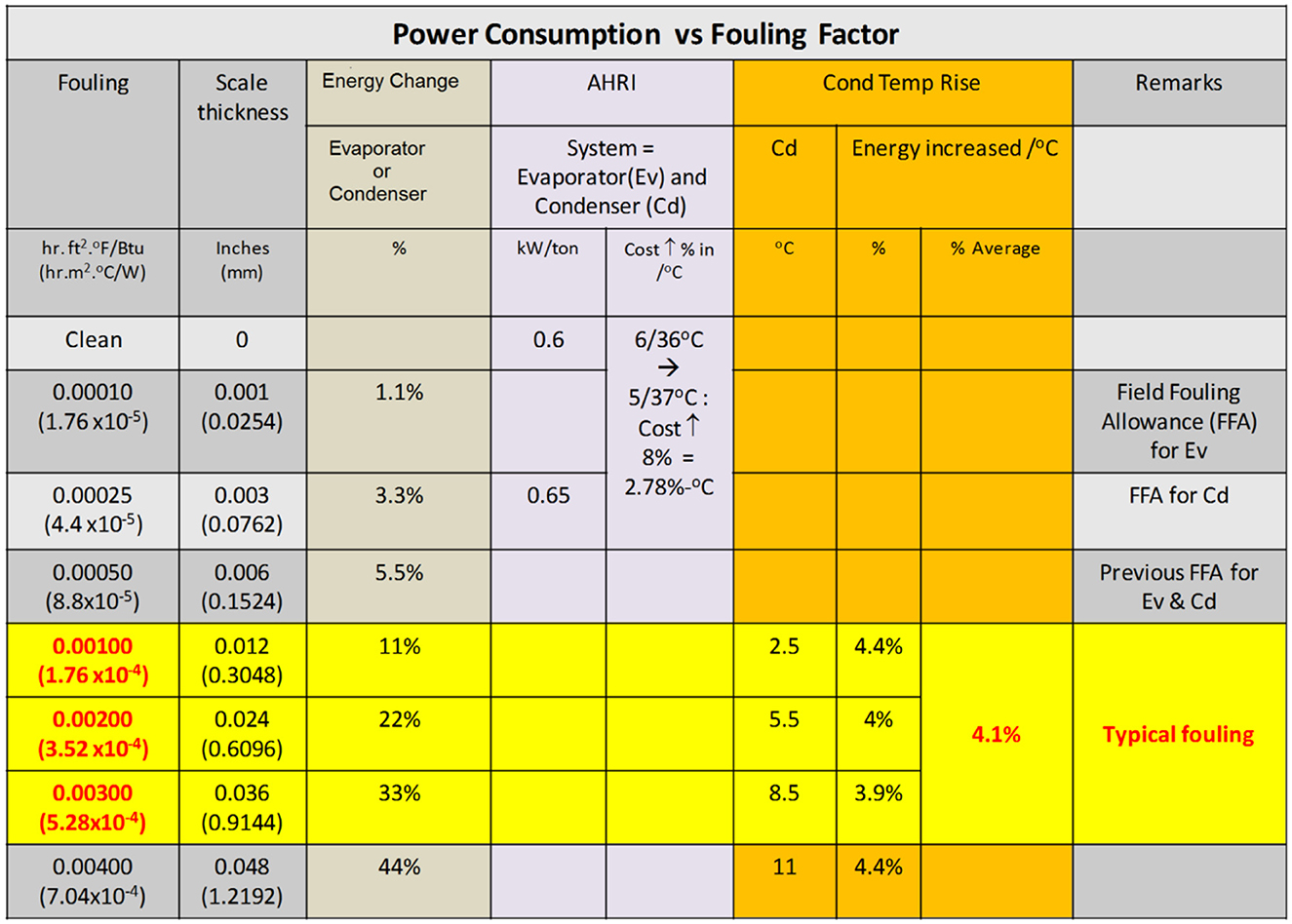
Figure 6. The correlation of Fouling factor and power under a wide range of evaporation and condensation.
The study for condenser approach temperature (CAT) change was carried out pre- and post- the condenser tube cleansing, which removed the water scale for better thermal conduction among the refrigerant, thermal surface, and cooling water flowing across the condenser tubes. Meanwhile, measurements for the condensing refrigerant temperature (CRT) change, which were to assess the energy performance and loss reduction from the removal of water scales as well as Case 2, were applied by increasing the cooling unit's speed to reduce the operation of CRT.
The evaporative cooling system was designed with a variable flow rate axial fan drawing the outdoor air through the baffles and cooling down the system water by evaporation. The heat exchange between the forced draw-in air and water was boosted by adjusting fan speed to accelerate the latent heat of vaporization. The cooled-down water was flowing to the condenser unit to cool the CRT, which is the refrigerant actual working condition, and then the chiller operations and power consumptions were logged for assessments.
The forced cooling is adjusted to a high flow rate, and hence the CRT is decreased by 0.7oC from 36.4°C. Obviously, the immediate benefit is the power consumption by the compressor, which is reduced by 12.3 kW from 255 kW. The energy utilization percentage is expressed as:
Case 2 has been adopted by changing the fan speed from low to high, improving the heat dissipation and obtaining an extra power saving improvement of 2.7%, which was interpreted as below:
Under the clean tube condition, a 4.2% decrease in input power, ikW, was theoretically assessed for the CRT from a temperature of 36°C down to a temperature of 30°C, while the actual CRT measurement of the existing chiller indicated 6.9% ikW input power improvement from CRT with 36.4°C down to CRT with 35.7 °C. The 2.7% difference in this measurement can be attributed to the various starting points of the CRT (SCRT). The higher SCRT of 36.4°C was used instead of the theoretical value of 36°C, resulting in a higher starting evaporator refrigerant temperature (SERT). The p–h curve is highly responsive to the refrigerant effect at higher SCRT, leading to a reduced power demand. This, in turn, results in a greater refrigeration effect and lower power requirement, leading to a higher COP than the theoretical value. The power benefits after implementing these practices are recorded in Figure 7A.
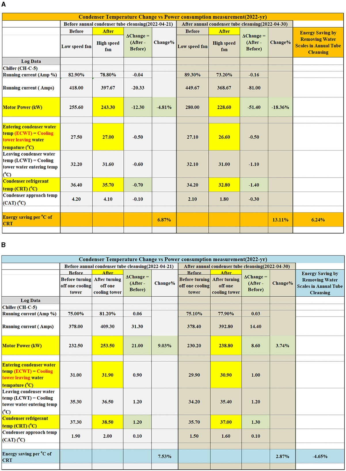
Figure 7. Measured CRT change after the cleansing of condenser tube (A) Case2 & (B) Case 1.
The present analysis and the measurement have indicated that there are actual measurements that indicated 6.87% energy saving per that 1 °C of CRT before cleansing. Following a tube cleaning, energy saving can be further achieved by a reduction of 13.11%/°C of CRT. It is a common concern that the aggravation of the scale is the peak just before the cleaning, and the use of descaling could contribute to around 50% of the power saving.
To compare the power consumption performance by CRT effect, Case 1 was carried out by reducing the number of operating water cooling towers water to decrease the heat dissipation that makes the CRT rise, as stated in Section 2.12. As per Figure 7B, the demand of power consumption was 7.53% per °C CRT increase before the condenser tube cleaning, which was 4.65% more than the 2.87% °C per CRT increase after the condenser tube cleaning, which was justified against the 2.4% power demand increment, as analyzed in Figure 5_Case 1 at clean tube surface conditions.
Both Case 1 and Case 2 have reflected the impacts of condensed water quality and have contributed to the overall cooling water quality improvement, which resulted in better condenser heat transfer and system performance. Improving the heat dissipation is commonly adopted for more energy saving in cooling tower operation mode.
The fouling of heat exchangers makes the heat transfer poor and the temperature difference of CAT becomes greater. The more foulants on the heat exchanger surfaces are deposited, the greater CAT will be. The condenser tube cleansing has been annually carried out to clean away the deposits and water scales for smaller or better CAT values as tabulated in Figure 8.
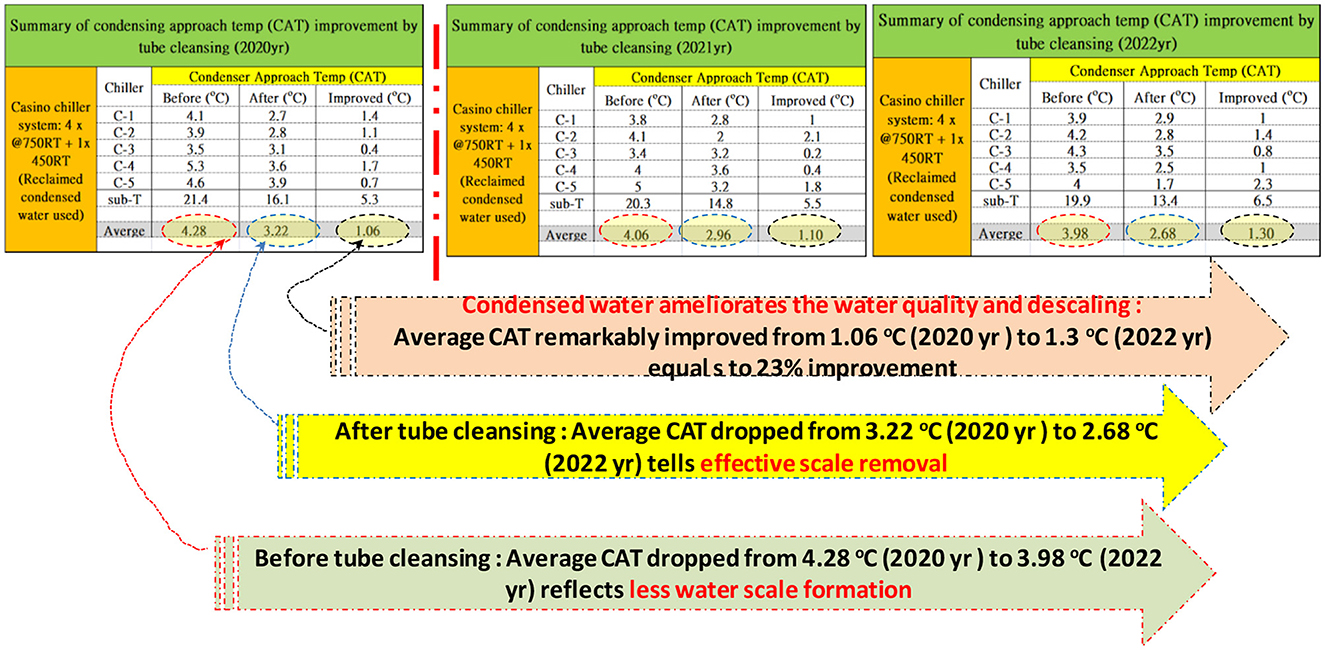
Figure 8. Condensing approach temperature (CAT) improvement by tube cleansing.
The system for auto BO and condensed water was finalized in April 2020, and then the average CAT improvement of the chiller system has been improved from 1.06°C to 1.3°C (i.e., 22.6% improvement). This remarkable overall CAT improvement was attributed to the less water scale formation, which was reflected by the average CAT dropping from 4.28°C to 3.98°C before the condenser tube cleansing, and the effective removal of water scales, which was indicated by the average CAT dropped from 3.22°C to 2.68°C, after the condenser's descale cleansing. The reclaimed water is conducive to sustaining better control of water quality and treatment that the less BO volume reduces the waste of chemicals and prolongs the residence time of chemicals. The slightly softened water nature fully extends the effectiveness of the antiscaling dosages that have made the stubborn water scales easier to remove during tube cleansing.
By annual routine maintenance, the water scale was cleaned away from condenser tubes, and the heat transfer efficiency was enhanced. From the condenser cleansing report for the chiller using reclaimed condensed water, the 1.30°C CAT improvement has been obtained just after tube cleansing, which gradually decreases to zero annually, and then the CAT improvement is half of the very first improvement figure just after the condenser tube cleansing is:
Over the summer of 2021, 13.8m3/day of condensed water was gathered, which aligns with the estimated volume of 13.2m3/day that could be obtained after 423 fan coil units (FCUs), and 1,646 domestic air conditioners (ACs) were installed. The FCUs were projected to generate about 17.28 L/day of condensed water, while the ACs were anticipated to produce around 36 L/day. The cooling tower was applied per reuse of condensed water and was operated using a temperature range of 4 °C on average, which saved 44% (i.e., 1,429 m3/month) of make-up water, which was theoretically assessed to 3,283 m3/month, as shown in Figure 9.
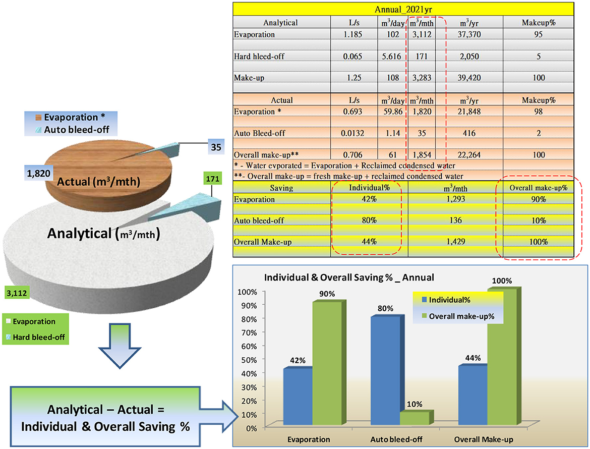
Figure 9. The description of energy utilization of cooling water.
Despite fluctuations in the environment and the load and the amount of condensed water produced, we have recorded a significant condensation of 5.66 m3 of water a day with a TDS of only 69 ppm in the 2021 study. That water was added back into the cooling water system with an increased dilution that was equivalent to the dilution provided by 10.64 m3 of water a day with a TDS of 130 ppm. By referring to the general practice of 2,500 ppm of TDS (i.e., 3,900 μS/cm) and the freshwater of TDS130 ppm, CoC of 19.2 was determined that the TDS 2,500 ppm was supervised with the EC controller, which controlled the programmed BOV to discharge the impurity-laden system water when the limit of TDS level was exceeded. Thus the BO effect was reduced to 1.14 m3/day, which is equivalent to 80%, that is, 4.476 m3/day, of the calculated hard BO daily volume of 5.616 m3, which was about 1/20 time of the calculated make-up water at 4.5 m3/h flow at CoC of 19.2, as per clause 2.4 above.
Having illustrated the direct water conservations from condensed water, which is just the tip of the iceberg, the other concealed advantages were the power consumption saving that has been brought by using the condensed water, which was beneficial to antiscaling and water quality.
The energy saving could be enhanced by the subcooling from the line suction heat exchange (LSHX), which ameliorated the refrigerant operating condition and temperature. With the energy saving assessments that were being taken with the CRT of 36°C and the ERT of 6°C, as stated in AHRI (AHRI, 1997), it was found that the CRT improvement could offer more energy saving than that of evaporating temperature. This has been illustrated in Figure 5 that the CRT improvement could obtain an energy saving of 4.2%, as indicated in Case 2, while the ERT improvement was 2.9%, as indicated in Case 3.
The fan of the cooling tower was speeded up to cool down the system cooling water and then the CRT. Meanwhile, the actual measurement of chiller consumption was carried out and analyzed that energy saving was 6.87% per °C of CRT (i.e., between 36.4°C and 35.7°C before the condenser cleansing, whereas energy saving was improved to over 13% per °C of CRT (i.e., between 34.2 °C and 32.8 °C) after the yearly condenser cleansing. As a result, the condenser tube cleansing achieved 3.12% per °C of CRT energy saving by the elimination of water deposits and scales.
In the civilized society that we are part of, freshwater shortage seems to be far from us. Ironically, there are still unexpected droughts, and water scarcity occurs from time to time in other parts of the world (Mahvi et al., 2013; Magrini et al., 2017). No matter how thorough your preparation is, there is a limit to the amount of water you can store. The atmospheric vapor is intangible but collectible by condensation from which the condensed water is reclaimed for cooling the water system. By far, the condensed water advantages had not been explicitly expressed and were under evaluation for use in water cooling towers, where they are commonly located at the highest working layer of an air-conditioning system or rooftop. In addition, this structural problem causes excess expenses for raising the reclaimed water to a high height, and also the amount and purity of condensed water varies significantly with the season, which is a drawback. Furthermore the given name “greywater” deterred the direct condensed water applications. This research has consolidated the practical exemplar of the direct application of condensed water for an evaporative cooling tower without the need for a wastewater treatment plant, which alleviates the limitations on the spatial requirement and power consumptions incurred. The intrinsic impurity-free condensation possesses the water augmentation that improves the quality and enhances water conservation and water scale abatement. These advantages contributed to the effectiveness of heat transfer, upgrading the performance of the power-intensive equipment, resulting in energy saving ultimately.
There are a few potential approaches to promote the condensed water reclaiming:
1. Device design: when designing new devices, consider incorporating a condensation capture system as a standard feature like refrigerators and de-humidifiers. Given that the air-conditioners, split units, and AHUs have already built-in condensate drain pans to receive the condensed water from the cooling coils, the collected condensation can be directed to specific drain points by the connecting field pipes to the outlets of the drain pans. To effectively manage all the equipment scattered throughout the building, they can be grouped and connected to exclusive pipe stacks that lead to the main capturing system of the complex building. Most modern developments are already designed with a condensate drain system that directly discharges the condensed water to a stormwater system or a similar system. Therefore, the additional infrastructure and cost would be for the condensed water storage and pump sets. In this particular case study, the implications are minimal, as the water tank only has a capacity of 1 m3, and no water lifting pump is required. This is because the condensed water can be directly used and flows to the cooling water tower by gravity. On the other hand, any modification and renovation in the latter stages would significantly increase the cost and time implications. This is especially true for considerations such as headroom requirements, spatial limitations, and practicability due to the congested mechanical and electrical service installations.
2. Improved collection system: executing improved systems to capture condensation can enhance the volume of reclaimed water. This might require refining the layout and positioning of collection surfaces, utilizing advanced materials, or integrating cutting-edge technologies.
3. System integration: integrating the reclaiming system using condensation together with the building management systems in the building can help enhance water circulation. For old buildings, retrofitting is needed, and it is relatively simple for a new building.
4. Thermal management: improving thermal insulation or the use of better materials to provide good conservation of temperature for both cooling and heating units also results in energy savings. This is a passive method, but the effect is very distinct.
5. Education, policy, and incentives: educating the building management on the use of reclaiming condensation water. The government may provide incentives such as tax allowances or rebate schemes. The proposal for water buyback is similar to the feed-in tariff for electricity or the high buyback electricity generation for renewable energy.
It is worth noting that the practicality and success of these methods may differ based on factors such as local laws, global environmental development, weather conditions, and the unique features of the structure. Nevertheless, by employing a list of water and energy management, it is feasible to enhance the reuse of collected water and support ecofriendly water organization in required structures for the cooling of modern buildings.
Solar power has been investigated to assist in the technology of water condensation. The present study for using solar power with water condensation technology is to use solar energy to power the cooling systems that facilitate condensation. By using solar power to run the cooling systems, the energy required for the condensation process can be sourced sustainably, reducing the overall environmental impact. This method is to free energy, as the present PV cost is very low.
It is also seen that solar power can also be used to run the pumps, monitor system, and other equipment needed for the collection and distribution of condensed water. This can help reduce the reliance on the building's electrical sources and further enhance the sustainability and energy conservation of the water condensation process.
The use of solar panels to assist in water condensation and many other building-related water technologies has emerged and is a downstream research development. The concept of using solar energy to drive atmospheric water generators or dehumidifiers, which extract water from the air using condensation processes powered by solar energy. While this technology has been very mature in home applications, it holds promise for providing a sustainable and renewable source of water in areas with limited access to freshwater or enhancement of water utilization. The use of PV is now a modern and low-cost solution to supply water conservation development. The method has been used in parallel with the condensation methodology in a building. It is an effective and sustainable operation of water reclaiming processes and provides ecofriendly water management to buildings and other ventilation-required facilities.
The global demand for energy saving and water conservation has triggered the research developed in this article. The condensed water is not a kind of greywater that exclusively requires a water treatment plant before application; it was simply reclaimed as free freshwater replenishment of the cooling and ventilation system.
Water conservation is the most superficial layer of benefits from using condensed water for the cooling system; the other layers underneath are the energy-saving layers resulting from the amelioration of thermal management of condensers and by the conduciveness to descaling and water quality control. The antiscaling chemicals could fully extend to the best efficacy before BO reduces chemical use and discharges. The burden of scale deposit and fouling developed an unwanted thermal resistance to reduce heat transfer from water circulation to the atmosphere at the cooling tower. The consequence is revealed by the CAT, whereas the CRT rise is interpreted straightly as more power required by the compressor.
In terms of energy saving, replacing a fluorescent lamp with LED is more tangible than saving a drop of condensed water; however, the intricate relationships between water and electrical power demands have been extricated from the interdisciplinary research of condensed water and heat transfer of condenser and cooling towers. By unveiling the benefits of condenser water, this research provided a solid ground for demonstrating that condensed water could enhance energy saving as well.
Entirely without prejudice, condensed water is a side-product of air conditioning, which is intrinsic, impurity-free, and very suitable for dilution of impurity-laden system water. The water and energy that pertains to condensed water reclaim is a promising answer to green buildings.
The significance of the research findings is to expedite the progress of condensed water reclaims for existing and new green building designs. The direct use of reclaimed condensed water, a by-product, demonstrated a feasible and low-cost practical application. The intrinsic impurity-free water quality ameliorated the system's performance in water and energy savings.
The future works will be on the new design of the thermal management system that is to use thermal circulation and heat sink management to facilitate heat removal or to reuse the heat management in the condensation water system. It consists of finned and large surface areas to assist the circulation of the condensed water, is typically mounted on the ceilings or walls of the target areas like a computer server room, or integrates chilled beams into the passive or active thermal design to remove the heat of the electronic components. Instead of relying solely on mechanical cooling systems, the pre-cooled water can take advantage of the inherent thermal energy, reducing the energy consumption required for cooling. As always, the small amount of condensed water may not be attractive for building management to recycle the water. However, a centralized condensed water system may increase the total water quality, size, water stability, and integrity.
Although the condensed water was easy to collect by gravity naturally and flowed to a lower layer water collection tank, other designs can also use an electric pump to assist the water collection at a higher speed and to relocate the tank at any level. This will relax the requirement of the collection tank location. Moreover, the water capturing system is not properly insulated, and heat losses were encountered in this existing high-rise building. Therefore, it is recommended to realize the thermal energy recycling from condensed water accomplished by an all-insulated condensed water circulation and storage system. The use of solar power is a method to further enhance water conservation, and it provides additional energy for the water circulation electrical system, also helping the condensation through the PV system.
The original contributions presented in the study are included in the article/supplementary material, further inquiries can be directed to the corresponding author.
Y-KL: Conceptualization, Data curation, Formal analysis, Investigation, Methodology, Writing – original draft. KC: Conceptualization, Methodology, Project administration, Resources, Supervision, Writing – review & editing.
The author(s) declare that no financial support was received for the research, authorship, and/or publication of this article.
The concept of this manuscript has been presented in: (i) The effectiveness of Reclaimed Condensed Water Used for an Evaporative Cooling Tower in Water Conservation and Energy Saving at the 2020 IEEE 8th International Conference on Power Electronics Systems and Applications (PESA). doi: 10.1109/PESA50370.2020.9343985. (ii) Part I & Part II of Unveiling the Benefits of Reclaimed Condensed Water at the 2022 IEEE 9th International Conference on Power Electronics Systems and Applications (PESA). doi: 10.1109/PESA55501.2022.10038364; doi: 10.1109/PESA55501.2022.10038365.
The authors declare that the research was conducted in the absence of any commercial or financial relationships that could be construed as a potential conflict of interest.
The author(s) declared that they were an editorial board member of Frontiers, at the time of submission. This had no impact on the peer review process and the final decision.
All claims expressed in this article are solely those of the authors and do not necessarily represent those of their affiliated organizations, or those of the publisher, the editors and the reviewers. Any product that may be evaluated in this article, or claim that may be made by its manufacturer, is not guaranteed or endorsed by the publisher.
AC, Air conditioning unit; AHU, Air handling unit; ASP, Antiscaling polymer; BOV, Bleed-off volume; CAS, Condensate assistant subcooling; CAT, Condensing approach temperature; CDP, Condensate drain pipe; CoC, Cycle of concentration; CRT, Condensing refrigerant temperature; ER, Electrical resistance; ERT, Evaporator refrigerant temperature; ECWT, Cooing tower leaving water temperature = Entering condenser water temperature; FCU, Fan coil unit; GHG, Greenhouse gas; LCWT, Cooling tower entering water temperature = Leaving condenser water temperature; LSHX, Liquid-suction heat exchanger; RH, Relative humidity; RT, Refrigerant tonnage; SERT, Starting point of ERT; SCRT, Starting point of the CRT; TDS, Total dissolved solids; VCRC, Vapor compression refrigeration cycle; DAG, The water dilution factor that is augmented by a reclaimed mechanism; BL, Rate of water bleed-off; BALHB, Authentic auto bleed-off capacity; Ca2+, Calcium ion (aq in the aqueous state); CaCO3(s), Calcium carbonates (s in solid state); CO2(g), Carbon dioxide (g fin gas state); CATAC, The annual average improvement of condensing approach temperature (CAT) after condenser tube cleansing in °C; DL, Drift losses; EV, Evaporation; hx, Enthalpy of point x of VCRC, unit in kJ/kg (x = 1 means after evaporator; x = 2 means after compressor; x = 3 means after condenser; and x = 4 means after expansion valve); h, Enthalpy of point x' of VCRC, unit in kJ/kg (x' = 1′ means superheated after evaporator; x'= 2′ means superheated after compressor; x' = 3′ means subcooled after condenser; and x' = 4′ means subcooled after expansion valve); P%ACS, The variation of CRT against the condenser tube cleansing; P%AFCS, The variation of CRT following condenser tube cleansing; P%BFCS, The variation of CRT before condenser tube cleansing; Tx, Temperature of point x unit in °C (x = 1 means after evaporator; x = 2 means after compressor; x = 3 means after condenser; x = 4 means after expansion valve); Tx', Temperature of point x unit in °C (x'= 1′ means superheated after evaporator; x'= 2′ means superheated after compressor; x'= 3′ means subcooled after condenser; x' = 4′ means subcooled after expansion valve); TDSTA, The TDS of condensed water collected in Tank A; TDSTB, The TDS of condensed water collected in Tank B; TDSTAB, The TDS of condensed water collected in Tanks A, B; Va, Flow volume of intake air passing through fan coil unit in m3/s; Vofcu, Specific volume of intake air passing through fan coil unit in m3/kg; VA, The physical size of condensed water reclaimed with Tank A; VB, The physical size of condensed water reclaimed with Tank B; EAE, The authentic measured flow of evaporation water at CoC 19 setting; RAR, The authentic measured flow for reclaimed condensed water; BAAB, The authentic measured flow for BO water under automatic BO setting at CoC 19; EAE, The authentic measured flow for evaporation water; MAM, The authentic measured flow for make-up water; B%AAB, The authentic BO flow of the water at CoC 19 setting; B%ABS, The astute BO water flow rate saving at CoC 19 setting; BALHB, The astute BO water flow rate without automatic BO system at CoC 19 setting; EALE, The astute evaporation water flow rate at CoC 19 setting; M%ALHB, The percentage of the astute BO water flow without automatic BO system at CoC 19 setting against the complete water usage; M%EQBDS, The ratio of equivalent water flow saving from the minimal auto bleed-off at high CoC 19.2 and the augmented dilution in percentage (%); MD, The equivalent physical size of water after the dilution accretion augmentation; MEQBDS, The total equivalent water saving come from the minimal auto bleed-off at high CoC of 19.2 and the augmented dilution; BRD, The astute BO water flow rate deduction at CoC of 19.
AHRI (1997). AHRI Guideline E, 1997 Guideline for Fouling Factors: A Survey of their Application in Today's Air Conditioning and Refrigeration Industry. Available online at: https://www.ahrinet.org/system/files/2023-06/AHRI_Guideline_E_1997.pdf (accessed December 13, 2023).
Bhatia, A. (2022). CED Engineering course 2022, M05-013, HVAC Enegry Conservation through Cooling Water Treatment. Available online at: https://www.cedengineering.com/courses/hvac-energy-conservation-through-cooling-water-treatment (accessed December 13, 2023).
Coker, A. K. (2015a). Refrigeration Systems, Ludwig's Applied Process Design for Chemical and Petrochemical Plants, 4th ed, 623–727.
Coker, A. K. (2015b), Compression Equipment, Ludwig's Applied Process Design for Chemical Petrochemical Plants, 4th ed. 729–978.
Engstler, E., Kerschbaumer, D. J., and Langergraber, G. (2022). Evaluating the performance of small wastewater treatment plants. Front. Environm. Sci. 10:948366. doi: 10.3389/fenvs.2022.948366
Filali, H., Barsan, N., Souguir, D., Nedeff, V., Tomozei, C., and Hachicha, M. (2022). Greywater as an alternative solution for a sustainable management of water resources—a review. Sustainability 14, 665. doi: 10.3390/su14020665
Fu, H., Dai, M., Song, H., Hou, X., Riaz, F., Li, S., et al. (2021). Updates on evaporation and condensation methods for the performance improvement of solar stills. Energies 14:7050. doi: 10.3390/en14217050
HKEMSD (2016). Part 3: Water Treatment Methods, Code of Practice for Fresh Water Cooling Tower. Available online at: https://www.emsd.gov.hk/filemanager/en/content_296/fwctCoP_Part_3.pdf (accessed December 13, 2023)
HKGBC (2010). “BEAM plus for exisiting buildings version 1.1.,” in Building Environmental Assessment Method, 55–12. Available online at: https://www.hkgbc.org.hk/eng/beam-plus/beam-plus-references/manuals-assessment/ManualsFiles/BEAMPlus_Existing_Buildings_v1_1.pdf (accessed December 13, 2023).
HKGBC (2012). “BEAM Plus For New Buildings version 1.2.,” in Building Environmental Assessment Method, 131. Available online at: https://www.beamsociety.org.hk/files/BEAM_Plus_For_New_Buildings_Version_1_2.pdf (accessed December 13, 2023).
Ismail, A. F., Khulbe, K. C., and Matsuura, T. (2019). “Chapter 8 - RO membrane fouling,” in Reverse Osmosis, eds. A. M. Ismail, K. C. Khulbe, and T. Matsuura (London: Elsevier), 189-220.
Judd, B. J. (2003). “Chapter 3 - Industrial waters,” in Membranes for Industrial Wastewater Recovery and Re-use (London: Elsevier Science), 75–101.
Khajvand, M., Mostafazadeh, A. K., Drogui, P., and Tyagi, A. K. (2022). Management of greywater: environmental impact, treatment, resource recovery, water recycling, and decentralization. Water Sci. Technol. 86, 909–937. doi: 10.2166/wst.2022.226
Lakos (2022). Scale Buildup vs Energy Consumption, Heat Transfer Filtration; Lakos filtration solutions. Available online at: https://recohvac.com/wp-content/uploads/2014/12/LAKOS-LS-580-HVAC-Solutions-Brochure.pdf (accessed December 13, 2023).
Magrini A. Cattani L. Cartesegna M. Magnani L. (2017) Water production from air conditioning systems: some evaluations about a sustainable use of resources. Sustainability 9:1309. 10.3390/su9081309
Mahvi, A. H., Alipour, V., and Rezaei, L. (2013). Atmospheric moisture condensation to water recovey by home air conditioners. Am. J. Appl. Sci. 10, 917–923. doi: 10.3844/ajassp.2013.917.923
Neveux, T., Bretaud, M., Chhim, N., Shakourzadeh, K., and Rapenne, S. (2016). Pilot plant experiments and modelling CaCO3 growth inhibition by the use of antiscalant polymers in recirculating cooling circuits. Desalination 397, 43–52. doi: 10.1016/j.desal.2016.06.018
Pottker, G., and Hrnjak, P. (2014). Experimental investigation of the effect of condenser subcooling in R134a and R1234yf air-conditioning systems with and without internal heat exchanger. Int. J. Refriger. 50, 104–113. doi: 10.1016/j.ijrefrig.2014.10.023
Siam, L., Al-Khatib, I. A., Anayah, F., Jodeh, S., Hanbali, G., Khalaf, B., and Deghles, A. (2019). Developing a strategy to recover condensate water from air conditioners in Palestine. Water 11:1696. doi: 10.3390/w11081696
SPX (2022). SPX cooling Technologies UK Ltd. Marley fibreglass cooling tower, NC fibreglass Engineering data and specification. Available online at: https://spxcooling.com/library/marley-nc-fiberglass-engineering-data-and-specifications-2/ (accessed on December 23, 2023)
Sumeru, K., Sukri, M. F., Falahuddin, M. A., and Setyawan, A. (2019). A review on sub-cooling in vapor compression refrigeration cycle for energy saving. Jurnal Teknologi. 81, 155–170. doi: 10.11113/jt.v81.13707
Keywords: water and energy saving, CoC, reclaimed condensed water, greywater, cooling tower
Citation: Leung Y-K and Cheng KWE (2024) The enhancement of water and energy conservation through condensed water reclamation for evaporative cooling towers. Front. Water 6:1357976. doi: 10.3389/frwa.2024.1357976
Received: 19 December 2023; Accepted: 23 May 2024;
Published: 03 July 2024.
Edited by:
Georgia A. Papacharalampous, National Technical University of Athens, GreeceReviewed by:
Mohammad Najafzadeh, Graduate University of Advanced Technology, IranCopyright © 2024 Leung and Cheng. This is an open-access article distributed under the terms of the Creative Commons Attribution License (CC BY). The use, distribution or reproduction in other forums is permitted, provided the original author(s) and the copyright owner(s) are credited and that the original publication in this journal is cited, in accordance with accepted academic practice. No use, distribution or reproduction is permitted which does not comply with these terms.
*Correspondence: Ka Wai Eric Cheng, ZWVlY2hlbmdAcG9seXUuZWR1Lmhr
Disclaimer: All claims expressed in this article are solely those of the authors and do not necessarily represent those of their affiliated organizations, or those of the publisher, the editors and the reviewers. Any product that may be evaluated in this article or claim that may be made by its manufacturer is not guaranteed or endorsed by the publisher.
Research integrity at Frontiers
Learn more about the work of our research integrity team to safeguard the quality of each article we publish.