 Chidera O. Iloejesi
 Lauren E. Beckingham
95% of researchers rate our articles as excellent or good
Learn more about the work of our research integrity team to safeguard the quality of each article we publish.
Find out more
ORIGINAL RESEARCH article
Front. Water , 26 August 2021
Sec. Water and Built Environment
Volume 3 - 2021 | https://doi.org/10.3389/frwa.2021.689404
This article is part of the Research Topic Frontiers in Water: Rising Stars 2021 View all 11 articles
Subsurface porous aquifers are being considered for use as reservoirs for compressed energy storage of renewable energy. In these systems, a gas is injected during times in which production exceeds demand and extracted for energy generation during periods of peak demand or scarcity in production. Current operational subsurface energy facilities use salt caverns for storage and air as the working gas. CO2 is potentially a more favorable choice of working gas where under storage conditions CO2 has high compressibility which can improve operational efficiency. However, the interaction of CO2 and brine at the boundary of the storage zone can produce a chemically active fluid which can result in mineral dissolution and precipitation reactions and alter the properties of the storage zone. This study seeks to understand the geochemical implications of utilization of CO2 as a working gas during injection, storage and extraction flow cycles. Here, reactive transport simulations are developed based on 7 h of injection, 11 h of withdrawal and 6 h of reservoir closure, corresponding to the schedule of the Pittsfield field test, for 15 years of operational life span to assess the geochemical evolution of the reservoir. The evolution in the storage system is compared to a continuously cyclic system of 12 h injection and extraction. The result of the study on operational schedule show that mineral reactivity occurs at the inlet of the domain. Furthermore, the porosity of the inner domain is preserved during the cycling of CO2 acidified brine for both systems.
- The viability of use of a reactive cushion gas in compressed energy storage system needs to be considered
- Reactivity at cushion gas boundary for operational schedules with and without storage are compared
- Geochemical reactions increase porosity close to the injection well but are otherwise limited
- Operational schedule does not largely impact geochemical reactions in a low carbonate mineral assemblage reservoir.
The global renewable energy share in terms of final energy consumption has increased over the past decade to 17.3% in 2017 (IEA, 2019). Increased utilization of renewables resulted from government policy incentives (Huang et al., 2007; Chandler, 2009; Lyon and Yin, 2010; Jenner et al., 2012), technical advancements (Álvarez-Herránz et al., 2017; Mensah et al., 2018; Lin and Zhu, 2019), and environmental benefits that promote social acceptance (Haar and Theyel, 2006; Aslani et al., 2012; Wang et al., 2018). Moreover, adopting renewable energy has been positively linked to economic development (Sadorsky, 2009a,b; Apergis and Payne, 2010) and reductions in anthropogenic greenhouse gas emissions while diversifying energy production (Lund, 2007; Chien and Hu, 2008; Marques et al., 2011; Chen et al., 2014). However, the intermittency of renewable energy production requires a reliable means of long term, large capacity energy storage to achieve energy security through renewable energy (van der Linden, 2006). Efforts to increase and improve energy storage have included fast discharging, low capacity options like lead-acid batteries to slow discharging, high capacity options like pumped hydro and compressed energy storage (Dunn et al., 2011). The high-capacity options store bulk energy in megawatts for hours to months, which offers increased reliability in grid-scale applications of renewable energy.
Compressed energy storage is a promising means of long-term, grid-scale energy storage that has the potential to be widely deployed across the globe in subsurface reservoir formations including salt caverns or porous saline aquifers (Aghahosseini and Breyer, 2018). In these systems, a working gas is injected into the storage formation during periods of excess energy production and extracted to power a turbine during periods of excess energy demand (Succar and Williams, 2008). Salt caverns, mined hard rock caverns and porous saline aquifers can be utilized as storage reservoirs (Allen, 1985). Energy storage has only been carried out in salt caverns to date (van der Linden, 2006). Salt caverns, however, are geographically limited. Porous saline aquifers, on the other hand, are ubiquitous which makes them a potentially more favorable option (Eckroad and Gyuk, 2003; Succar and Williams, 2008). The idea of extending the compressed energy storage medium beyond the currently used salt caverns to porous aquifers will facilitate more widespread possible utilization of this technology for municipal energy storage.
To initialize the system in a porous aquifer, a cushion gas may first be permanently injected into the porous formation to raise background pressure to help increase working gas recovery (Carden and Paterson, 1979). The cushion gas is injected into the formation to buffer the pressure fluctuation during the cycling of a working gas during energy storage. Hence, the compressibility of the cushion gas is thus an important consideration in helping to improve the economics and efficiency of compressed energy storage. The injection of these storage gases stratifies the porous saline aquifer into zones with varying compositions of gas to brine ratio (Cui et al., 2018). Although, these zones may not be distinctly classified and there could be mixing of working gas and cushion gas at the interface of the two gases (Kim et al., 2015). Furthest from the injection well is the zone where the cushion gas and the brine interface. At this zone, gas dissolution into the brine is controlled by mutual solubilities (Beckingham and Winningham, 2019).
For over eight decades that subsurface storage has been prevalent (Carden and Paterson, 1979; Allen, 1985), a variety of gases have been considered as cushion and working gases including nitrogen (Bauer et al., 2015; Pfeiffer and Bauer, 2015), native methane (Oldenburg, 2003), and air (Succar and Williams, 2008). It was in the wake of geologic CO2 sequestration that studies began to investigate the potential of using CO2 as cushion gas. At the typical depth of saline aquifers, CO2 becomes a supercritical fluid with a high density and compressibility. This makes it a particularly favorable choice of cushion gas where its high compressibility may improve available storage capacity, recovery and efficiency (Oldenburg, 2003). Further consideration of the compressibility of CO2 shows that using CO2 as cushion gas can help reduce significant pressure variation during working gas cycling (Oldenburg and Pan, 2013). An additional positive benefit of using CO2, a major greenhouse gas, is that it can remain permanently sequestered in the storage formation once injected. This is because the compressed energy system is designed to recycle only the working gas while the cushion gas remains permanently in the formation. Hence, utilizing CO2 for this purpose would provide potential environmental benefits and economic benefits in the form of 45Q tax credits (Mai et al., 2016). However, careful system design needs to be considered to not produce CO2 during the extraction of the working gas (Oldenburg and Pan, 2013). This can lead to pressure losses in the formation that affect working gas recovery (Ma et al., 2019). Also, failure to sequester CO2 while being used as cushion gas could offset potential tax credits gained by using CO2 as a cushion gas (Rul Internal Revenue Service, 2009). It should also be noted that CO2 can also be used as the working gas but this would require using a closed-loop system to exploit the beneficial physical properties of CO2 for energy production while ensuring that none escapes to the atmosphere (Alami et al., 2019).
Injecting CO2 in porous saline aquifers, however, introduces additional technical complexities that need to be considered before adoption. This includes a need to understand possible geochemical limitations that can result from interactions between the injected gas, formation brine, and formation minerals. One of the key geochemical considerations is the interaction of the aquifer formation with the cushion gas which occupies one-third of the total storage volume (Walters, 1976). While CO2 is a favorable choice of cushion gas from its physical property point of view, there could be potential geochemical implications of reactions between CO2, formation brine, and formation minerals that could pose to be a challenge to system operation (Zhang and Huisingh, 2017). These reactions, however, have not largely been considered. Injecting reactive fluids like CO2 in the subsurface can acidify the formation brine and result in complex mineral dissolution and precipitation reactions within the formation rock matrix, as has been observed in the context of geologic CO2 sequestration (Gunter et al., 1993; Fischer et al., 2010; Kharaka and Cole, 2011; DePaolo and Cole, 2013).
Flow conditions in geologic CO2 sequestration systems are distinctly different than those in energy storage systems. In geologic CO2 sequestration systems, flow is predominately unidirectional away from the injection well while energy storage systems utilize cyclic, bi-directional flow conditions as a result of the injection and extraction of the working gas and may contain intermittent storage periods. Previous reactive transport simulations have considered the impact of cyclic flow conditions on geochemical reactions in energy storage systems in a porous saline aquifer. These simulations have shown that the rate and extent of potential dissolution and precipitation reactions at three locations in the formation are significantly reduced in the energy storage system in comparison to what is anticipated in geologic CO2 sequestration system (Iloejesi and Beckingham, 2021). While this result is promising, the study only considered a 4 month operational period with constant injection and extraction cycling. These flow conditions can be referred to as a continuous operational schedule. To fully assess reactivity, longer time durations and variations in operational regime need to be considered. Operational schedules in most subsurface storage aquifers integrate periods of storage or shut-in. This is when the injected gas is allowed to sit in the aquifer with little to no flow before it is extracted to meet energy demand. This operational schedule can be referred to as a periodic schedule. The resulting geochemical reactions at the cushion gas boundary and implications for these types of operating conditions have not been considered.
This study aims to enhance understanding of the rate and extent of potential geochemical reactions in a porous saline aquifer utilized for energy storage which operates using a periodic schedule. This is done by comparing the difference between the geochemical evolution of a porous aquifer compressed energy storage system operating with a continuous schedule with the geochemical evolution when the system operates using the periodic operational schedule. Here, reactive transport simulations are developed considering daily cyclic interactions between the cushion gas (CO2), formation brine, and formation minerals over a 15 years study period. The evolution of major ions in the formation brine, formation minerals, and porosity for each system is tracked and compared to aid in the understanding of the use of CO2 as a cushion gas for compressed energy storage systems in porous saline aquifers operating with periodic schedule.
The impact of using CO2 as a cushion gas for energy storage in porous saline aquifer formations is considered here through reactive transport simulations. Simulations consider a case study of energy storage in the Paluxy formation for two operational regimes, one with a storage period and one without.
The Paluxy formation is considered here as a potential storage reservoir. This formation has been considered for CO2 enhanced oil recovery (Robinson and Davis, 2012) and geologic CO2 storage projects (Petrusak et al., 2010; Qin and Beckingham, 2019; Bensinger and Beckingham, 2020). Previous investigation of this formation has found it as high porosity, high permeability sandstone (Pashin et al., 2018; Bensinger and Beckingham, 2020). This formation is predominantly quartz (76.45%) with 9.64% calcite, 8.23% smectite, and the remainder minor phases (<5%), as determined from SEM imaging analysis in Qin and Beckingham (2019), where the mineral abundances are given in Table 1. The porosity of the sample obtained from image segmentation is 24.84% and the calculated permeability, as estimated using pore network modeling in Bensinger and Beckingham (2020), is 1414.3 mD.
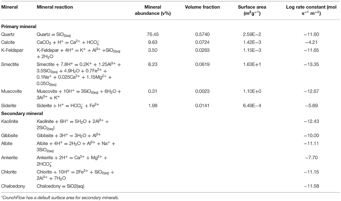
Table 1. Mineral abundance as percent volume, volume fraction, and surface area of the Paluxy formation obtained from multi-scale imaging of the sample in Qin and Beckingham (2019) and rate constants for the respective mineral phases at reservoir condition as obtained from the literature for quartz (Knauss and Wolery, 1988; Brady and Walther, 1990), calcite (Alkattan et al., 1998), K-Feldspar (Bevan and Savage, 1989), Smectite (Amram and Ganor, 2005), Muscovite (Oelkers et al., 2008), and Siderite (Golubev et al., 2009).
Reactive transport simulations to understand the geochemical evolution of the reservoir in the brine-saturated region surrounding the gas plume were developed here for energy storage systems using CO2 as a cushion gas. Here, the initial simulations developed in Iloejesi and Beckingham (2021) are extended to consider two storage operational schedules for 15 years. Simulations were developed in CrunchFlow, a multi-species reactive transport simulation code (Steefel and Molins, 2009). CrunchFlow has been used extensively used to understand subsurface geochemical reactions (Zhang et al., 2015; Dávila et al., 2016).
To consider the most reactive zone in the storage system, the acidified-brine zone adjacent to the two-phase zone, where brine and supercritical CO2 exist, was considered here (Figure 1). In this region, CO2 will dissolve into the brine phase, creating a region of acidified-brine favorable for geochemical reactions in the system (Huq et al., 2015). Here, a simplified system that ignores the advective mixing of the brine with CO2 is considered to maximize brine acidification and resulting reactivity. Here, a 15-cm domain in the acidified-brine zone was selected for simulations. The model domain was discretized into 45 equally spaced grid cells. The model domain was bounded by upstream and downstream “ghost” cells that serve as the boundary condition in the one-dimensional flow through simulation. The upstream “ghost cell” is the closest grid cell to the injection well. For ease of comparison of the concentration of major ion species, mineral volume fractions, and porosity evolutions, the model system evolution is monitored across the domain at select time intervals.
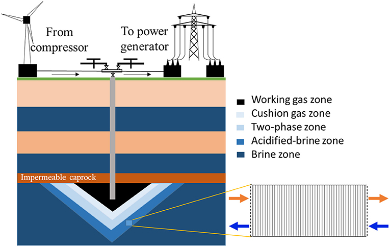
Figure 1. Schematic of the energy storage system and model domain for the reactive transport simulations. The “two-phase zone” corresponds to the presence of brine and cushion gas.
Two daily operational schedules were used in this study, one consisting of a periodic operational schedule that includes a storage period and the other a continuous operational schedule without the storage period. We refer to the flow condition for the continuous schedule as the injection–extraction flow regime and the flow condition for the periodic schedule as the injection–storage–extraction flow regime. One cycle of the continuous schedule consisted of a 12 h injection period followed by a 12 h extraction period. One cycle of the periodic schedule incorporated a 6 h storage period between 7 h of injection and 11 h of extraction. The periodic schedule is similar to the schedule used during the Pittsburg, Illinois field test (Allen, 1981; Allen et al., 1983). In both simulations, the duration of injection corresponded to flow of CO2 saturated brine away from the injection well supplied by a “ghost” boundary cell. The effluent brine was captured in the downstream boundary “ghost” cell and recycled during the extraction period. The upstream boundary or “ghost” cell served as a catchment for the effluent during the extraction period. The captured brine was then recycled through the model domain during the next injection period. As such, the composition of the influent brine for each component of the flow cycle was based on the effluent of the preceding period of the flow cycle. The influent brine for each injection period, however, was first equilibrated with CO2 before flowing through the model domain. For the flow regime that incorporated storage, flow was ceased during storage period and the system effectively resembled a batch system. In both operational regimes, a complete cycle took 24-h which corresponds to a compressed energy storage system used daily for power generation (Allen et al., 1983; Pfeiffer et al., 2017; Fleming et al., 2018). Simulations for each operational regime were carried out for a 15 year study period.
The model system was assumed as a homogenous and isotropic domain and initialized based on the mineral compositions, surface areas, and porosity from Qin and Beckingham (2019). The initial brine composition was calculated based on a 1 M NaCl brine in equilibrium with formation minerals for 10,000 years at reservoir temperature and pressure (Xu et al., 2007; Qin and Beckingham, 2021). The corresponding reservoir temperature and pressures were 50oC and 100 bar based on the geothermal gradient at Kemper, Mississippi and a typical pressure gradient (Nathenson and Guffanti, 1988; Bachu, 2000; Reysa, 2005). The pH of the brine was determined via charge balance. The CO2 saturated brine composition was determined by equilibrating brine with a constant partial pressure of CO2 at the depth of storage in the Paluxy formation. The Duan CO2 solubility model, which factors for high pressure and temperature conditions, was used to calculate the CO2 solubility in brine (Duan et al., 2006). A brine flowrate of 0.489 m/day was used for the continuous schedule. The flowrate is extrapolated for the Paluxy reservoir conditions from field-scale simulations of brine fluid velocities adjacent to injected CO2 plumes in a similar reservoir condition (Zhang and DePaolo, 2017). Two different flow rates were used for the periodic operational schedule to maintain pore volumes equal to the continuous operational system during each 24-h cycle. Flowrates of 0.838 m/day was used for the 7 h injection period and 0.533 m/day used for the 11 h extraction period (Table 2).
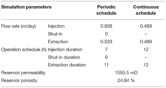
Table 2. Simulation Parameters for the periodic and continuous simulation model.
Mineral reactions in CrunchFlow are simulated using a rate law based on transition state theory. The corresponding parallel rate laws are given by,
where rs is the reaction rate, A is the reactive surface area of a constituting mineral in the rock sample, k is the equilibrium dissolution rate constant, n and M are exponents which are experimentally determined to explain nonlinear dependence of the dependence on oversaturation, Ks is the equilibrium constant, and Qs is the ion activity product for the rock–water interaction (Steefel et al., 2015). Here, reaction rate constants from previously published experimental works were extrapolated to formation conditions, following the method in Beckingham et al. (2017). Mineral accessible surface areas determined from a multi-scale imaging analysis in Qin and Beckingham (2019) on a sample from the Paluxy formation were used here as reactive surface areas. These surface areas reflect the mineral surfaces accessible to reactive fluids in the formation. The aqueous activity coefficients of the brine solution were calculated using the extended Debye-Huckle model as given by,
where γ± is activity coefficient of a completely dissociated binary electrolyte consisting of ions with charges Z+Z−, Aγ and Bγ are Helgeson's extended Debye-Huckle constant, I is the trues ionic strength and a, bγ are empirical parameter characteristic of the electrolyte (Helgeson and Kirkham, 1974). The extended Debye-Huckel equation applies to dilute solution where concentration is < ~1 molal (Xu et al., 2017).
The results of the reactive transport simulations for the continuous and periodic operational schedules are presented here. For each simulation, the evolution of the mineral volume fractions and saturation index of mineral phases, including the potential for secondary mineral precipitation, is tracked. The resulting evolution of porosity is then presented.
The simulated evolution of mineral volume fractions across the domain length for the continuous operational schedule (cyclic injection and extraction) are shown in Figure 2. During the first cycle, the flow of acidified brine into the domain during injection results in rapid dissolution of calcite close to the injection point. This increases the calcium ion concentration (Supplementary Figure 1) and buffers the pH (Supplementary Figure 1) such that no additional calcite dissolution occurs further away from the source of injection (Supplementary Figure 2). Siderite also dissolves resulting in an increase in iron concentrations and further buffering of the pH. Dissolution of siderite occurs throughout the domain with greater extents of dissolution closer to the injection well where the brine is the most undersaturated with respect to siderite. Smectite dissolves equally across the simulation domain during the first injection cycle. Smectite dissolution results in a brief period of early supersaturation and precipitation of muscovite, shown by the increase in muscovite volume fraction in Supplementary Figure 2. This is followed by slight dissolution of muscovite throughout the domain at later times. Quartz and K-feldspar remain stable across the domain throughout the first injection period.
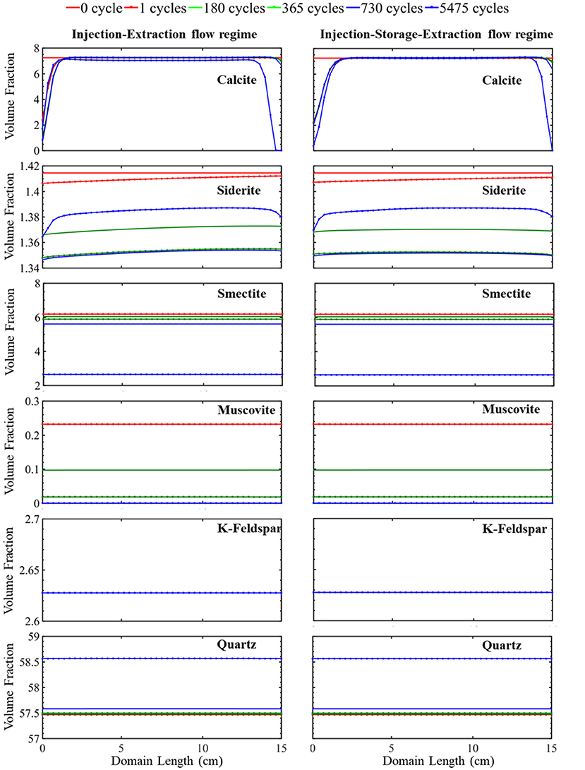
Figure 2. The simulated evolution of mineral volume fractions across the simulation domain at certain times over 15 years for the injection–extraction flow regimes (left) and injection–storage–extraction flow regimes (right). 0 h is the initial condition, and 15 years is the last condition of the porous media. Red reflects 0 h, dotted red 1 day, green 0.5 years, dotted green 1 year, blue 2 years, and dotted blue 15 years.
After 12 h, the flow reverses as the first extraction cycle begins and continues until 24 h. During this period, a constant composition brine, corresponding to the brine composition at the end of the proceeding injection cycle, enters the domain at the location furthest from the injection well and flows toward the injection well. The recycled brine has a pH of 4.93 (Supplementary Figure 1) and results in dissolution of siderite, producing iron ions (Supplementary Figure 1). The dissolution rate of siderite is the highest furthest from the injection well, where the distance from equilibrium is greatest and reduces closer to the injection well as iron concentrations in solution increase. Smectite dissolves across the simulation domain at a relatively constant dissolution rate. No additional calcite dissolution occurs during this period due to elevated calcium ion concentrations in the solution from dissolution during the proceeding injection cycle. Muscovite, quartz and K-feldspar remain stable.
The second injection period begins after 24 h. During this period, a constant composition brine saturated with CO2 enters the simulation domain. As the brine is recycled, the ion concentrations from the proceeding extraction period are maintained with additional acid added from equilibrium with the adjacent CO2 plume. This results in conditions favorable for additional mineral dissolution, most notably siderite and smectite which are still undersaturated in solution. No additional calcite dissolution occurs because of the high concentration of calcium in the brine.
This continuous cycling of injection and extraction continues over the 15-year study period and the resulting simulated evolution of mineral volume fractions are shown in Figure 2. Muscovite continuously dissolves and is completely consumed within the first 1.5 years. The dissolution of muscovite results in an increase in the concentrations of potassium, aluminum, and silicate ions. Released ions, from muscovite and other dissolving phases, create conditions favorable for formation of secondary mineral phases where saturation indices for potential secondary mineral phases are given in Figure 3. Chlorite precipitation is promoted by muscovite and siderite dissolution where siderite dissolves throughout the domain during the first 1.5 years. Once muscovite is consumed, siderite starts precipitating (Supplementary Figure 3) as conditions no longer favor chlorite precipitation as shown in equation 3 through equation 5. An increase in smectite dissolution also occurs, increasing magnesium ion concentrations. The elevated concentrations of calcium and magnesium ions in the brine result in ankerite precipitation. As calcium is consumed with ankerite precipitation, calcite dissolution is again favored starting at 1.5 years and calcite is completely depleted near the injection well after 5.5 years. The elevated silica concentrations from dissolution of muscovite and smectite also result in conditions favorable for precipitation of chalcedony. Conditions are also favorable for precipitation of gibbsite, kaolinite, and albite (Figure 3). K-feldspar remains stable throughout the simulation.
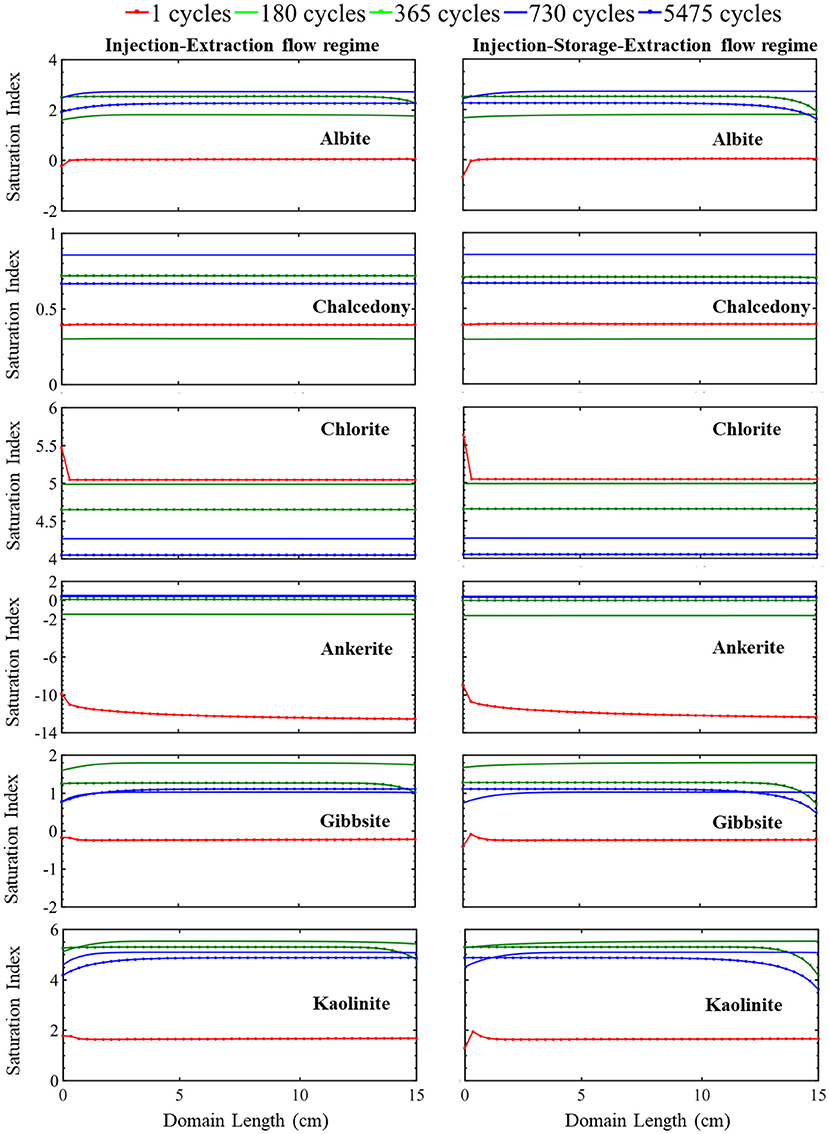
Figure 3. The simulated evolution of mineral saturation index across the simulation domain at certain times over 15 years for the injection-extraction flow regimes (left) and injection–storage–extraction flow regimes (right). A positive saturation index indicates precipitation potential and negative precipitation index indicates dissolution potential. The dotted red line is 1 day, green 0.5 years, dotted green 1 year, blue 2 years, and dotted blue 15 years.
The simulated evolution of mineral volume fractions for the operational schedule that includes the storage period is shown in Figure 2. In this simulation, 7 h of injection is followed by 6 h of storage and 11 h of extraction. During injection, acidified brine flows through the domain away from the injection well at a flowrate of 0.838 m/day for a period of 7 h corresponding to a period of excess energy production. During storage, flow slows to 0 m/day for a period of 7 h, resembling a batch reactor. During extraction, flow recycles back toward the injection well at a rate of 0.533 m/day reflecting the extraction of stored energy from the formation. Overall, injection, storage, and extraction result in the dissolution of calcite at the simulation domain boundaries and siderite, smectite, and muscovite dissolution throughout the simulation domain. Quartz precipitation occurs throughout the simulation domain.
Variations in the evolution of minerals due to the two operational schedules are most easily compared by considering calcite and siderite. Noted differences in these minerals occur closest and furthest from the injection well, especially within the first two cycles (Supplementary Figure 2). Both simulations have equal pore volumes, or amount of fluid flow, during injection and extraction periods. Therefore, flow rates are higher in the injection–storage–extraction operational schedule to compensate for the shorter flow duration. In both systems, flow of acidified brine into the system during the first injection period results in rapid dissolution of calcite and siderite. Injection continues for 12 h in the continuous schedule and 7 h in the periodic schedule. The prolonged period of injection in the continuous schedule results in additional calcite and siderite dissolution near the injection well even though the flowrate is higher for the injection–storage–extraction schedule.
After the 7 h of injection, a 6-h storage period with no flow begins in the periodic schedule. During this storage time, the elimination of the transport component of the reaction slows the reactivity of calcite and siderite. The reduction in reactivity is more noted in calcite than siderite as calcite is almost stable during the following storage period. On the other hand, smectite and muscovite dissolution behavior is unaffected by the storage period. Quartz and K-Feldspar maintain their early stability through the first storage period.
The first extraction period begins after 13 h in the periodic schedule and goes on for 11 h. During this time, the recycled brine returns through the system, flowing toward the injection well. The elevated calcium concentrations in solution prevent calcite dissolution. The dissolution rate of siderite, however, increases and is highest at the location furthest from the injection well, closest to the source of brine injection during the extraction period. The extent of dissolution during extraction is higher in the injection–storage–extraction system in comparison to the continuous operational schedule system. This is because more siderite dissolves in the continuous schedule during the injection period, resulting in a higher saturation of the brine with respect to siderite that limits the extent of siderite dissolution during extraction. In comparison, lower iron concentrations in the recycling brine following storage drive additional dissolution during extraction for the periodic schedule.
Overall, there is not a significant variation in the evolution of minerals between the two operational schedules. In both systems, initial calcite and siderite dissolution buffer the pH. Muscovite dissolves throughout the domain and is completely consumed within the first 1.5 years of simulation in both operational schedules. This complete dissolution of muscovite impacts the reaction pathway of siderite and calcite where the calcite dissolution rate increases as siderite begins to precipitate. Smectite dissolves at a similar dissolution rate in both the continuous and periodic operational schedule. Released ions from dissolving minerals create conditions favoring precipitation of similar secondary mineral phases (Figure 3). After 1.5 years, quartz, which was initially stable within the domain, starts to precipitate. K-feldspar remains stable in both systems throughout the simulation timeline.
The simulated evolution of porosity for the continuous and periodic schedules is shown in Figure 4. As evident in this figure, energy storage results in a non-uniform increase in porosity throughout the simulation domain. The porosity evolution depends on the rate and extent of dissolving minerals. Here, calcite, siderite, smectite, and muscovite dissolve. While muscovite completely dissolves, its small volume fraction (0.23%) does not largely contribute to porosity evolution. Instead, porosity is predominantly controlled by calcite, smectite, and quartz. Smectite dissolves relatively uniformly throughout the simulation domain, increasing porosity relatively uniformly by 3.54%. Conversely, quartz precipitates uniformly across the domain and reduces the porosity by 4.58%. It should be noted, however, that the extent of precipitation may be overestimated with the TST approach that does not account for nucleation and growth (Bourg et al., 2015). Calcite dissolves non-uniformly throughout the domain, increasing porosity by 5.55–7.24% and the evolution of porosity reflects the variation in calcite volume fraction over time. From the simulation results, it can be seen that elevated ion concentrations in the recycling brine create conditions favorable for precipitation of other secondary mineral phases. However, the impact of secondary minerals on porosity evolution is insignificant where the largest volume fraction of a secondary mineral is three order of magnitude lower than the primary minerals in the system.
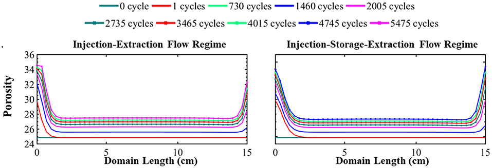
Figure 4. The simulated evolution of porosity across the simulation domain over 15 years for the injection–extraction flow regime (left) and injection–storage–extraction flow regime (right). 0 years (dark green) is the initial condition and 15 years (dotted magenta) is the final condition. Red is 1 day, light green 2 years, blue 4 years, magenta 5.5 years, dotted dark green 7.5 years, dotted red 9.5 years, dotted light green 11 years, dotted blue 13 years, and dotted magenta 15 years.
The main differences in the porosity evolution between the two operational regimes occurs near the boundaries of the simulation. After the first injection of acidified brine, the difference in porosity between the systems is 1.33 percentage points with a porosity of 29.86% in the periodic system and 31.19% in the continuous system near the injection well. Brine saturation, the duration of flow, and flow rate all impact the rate of mineral dissolution and precipitation. The intense mineral dissolution in the first cycle, which occurs to greater extremes in the continuous schedule, results in elevated saturation conditions in the brine that control further reaction in the system. Thus, the subsequent cycling of the brine results in slightly more dissolution of minerals in the periodic schedule in comparison to the continuous schedule. As a result, the initial 1.33 percentage point difference in porosity reduces over time. After 15 years of operation, the porosity difference near the injection well is only 0.38 percent point difference. At the end of the simulation, the difference in porosity furthest from the injection well is 1.71 percentage point where the final porosity is 33.08% in the continuous schedule and 34.79% in the periodic schedule. This difference is because there is less dissolution during extraction for the continuous schedule due to the effect of prolonged periods of reaction during injection which further saturate the brine as compared to the periodic schedule. In addition, the lack of transport during the storage period builds up high concentrations of species from dissolving minerals while species involved in mineral precipitation reactions are depleted, reducing the driving forces for dissolution and precipitation following the storage period (Fig S4). Similar porosity evolution occurs in the middle locations in both systems where there is a moderate increase in porosity throughout the middle of the domain (Figure 4) in both operational schedules even after 15 years of operation.
Most of the porosity change occurs within the first year of system operation, regardless of operational schedule. Overall, the system attained 86 and 91% of its final porosity within the first year. This can serve as a guideline to know that using CO2 as a cushion gas will require adequate monitoring during the early stages of the project, but extensive continued modification of the formation is less likely following this period.
The previous discussion is based on the comparison of model systems with equal pore volumes of acidified brine flowing through the domain during each cycle. This results in an increased injection rate for the system with the storage period. However, the periodic schedule system may instead operate with the same injection rate as in the continuous schedule as a result of the energy production rate or attempts to control the bottom hole pressure condition. Hence, this section compares the mineral evolution in the reservoir for the periodic schedule designed for equal pore volume of flow (discussed above) with a new low injection rate condition designed for equal flow rates as compared to the continuous schedule. Since we have identified higher reactivity during the early stages of cycling the working gas in this system, this investigation was carried out considering a 4 month study period to understand the impact of flowrate on the mineral evolution in the system. The relative volume fractions and relative porosity plot in Supplementary Figure 5 are generated from the ratio of the volume fractions and porosity, respectively, during the high flow rate condition to the low flowrate condition.
Comparing the evolution of mineral volume fractions for the two different flow rates, we see that smectite and other less reactive minerals like quartz and K-feldspar are insensitive to changes in flowrate. The evolution of the relative volume fraction of muscovite shows that more muscovite dissolves at the beginning of the simulation in the location closest to the injection well under the high flow rate condition. As a result, less muscovite dissolves further away from the injection well given the higher species saturation of the brine which limits further muscovite dissolution. Overall, however, the difference in the amount of muscovite dissolution is small (3.5%) during this period. The dissolution of highly reactive minerals like siderite and calcite increases with increasing flowrate. This increase is very significant for calcite at the location closest to the injection well. The evolution of the relative volume fraction of calcite reinforces the idea that low flowrates are required to sustain the reactivity throughout the domain as less calcite dissolution occurs at the location furthest from the injection well in the high flow rate conditions. Siderite dissolution, however, is slightly higher throughout the domain in the high flow rate conditions. Overall, the impact of flow rate on porosity is limited. Higher flowrates favor increased porosity near the injection well resulting in a 2% increase in porosity in comparison to the lower flow rate conditions. Conversely, lower flow rates favor porosity increase in locations furthest from the injection well. There is limited difference in the porosity evolution for the two flowrates at the central location of the domain. While some differences in the extent of reaction occur with different flow rates, the overall change in porosity in the system is similar and limited, mainly increasing near the injection well.
This study has shown that cycling of acidified brine presents the potential for porosity change in the formation especially near the injection well. Furthermore, this porosity evolution has been shown to be somewhat sensitive to the variation in flowrate. Here, the resulting change in permeability along the domain is estimated using the Kozeny-Carmen porosity-permeability relationship (Carman, 1997) as shown below.
Where K is permeability, ∅ is porosity, c is Kozeny constant, and S is specific surface area. The Kozeny-Carmen equation parameters was obtained from a study on the pore network and permeability evolution of the Paluxy formation has the value of c as 2.8 and S as 0.083μm−1 (Bensinger and Beckingham, 2020). Hence, the initial porosity of 24.83% was used to calculate an initial permeability of 1,414.3mD. These values were then used to develop the plot of the percentage change in porosity and percentage change in permeability along the domain after the 15 years study period in Supplementary Figure 6. The values of the percentage change in porosity varies from 9.79 to 28.62% and permeability varies from 31.13 to 71.40% for the periodic flow regime. The range for the percentage change in porosity for the continuous schedule is 10.21–28.63% and permeability is 32.94–72.65%. However, the change in permeability depends on the spatial distribution of mineral reactions within the pore network where pore network model simulations of reactions in the Paluxy formation in Bensinger and Beckingham (2020) found increases in porosity to 34.8% can result in permeability of ~ 1100–7000mD. As already mentioned, the higher values of percentage change in porosity and permeability occur at the extremes of the domain. The total impacted domain length is 2.64 cm in a 15 cm domain length of porous media where there is more than an 11% change in porosity under the two flow regime. The changes in porosity and permeability presented here could be higher in a more reactive formation matrix and lower with a less reactive mineral assemblage.
Utilizing CO2 as a cushion gas compressed energy storage in porous formations introduces new uncertainties in terms of the reactivity between the injected gas and surrounding matrix. Earlier reactive transport simulations have suggested that the extent of reactions between injected CO2, brine, and formation minerals will be limited in compressed energy storage system in comparison to geologic CO2 sequestration (Iloejesi and Beckingham, 2021). Here, variations in operational regime on geochemical reactions at the plume boundary have been explored.
Flow in energy storage systems with and without storage periods is distinctly different. Without a storage period, there is a constant cyclic flow away from and toward the injection well as excess energy is injected and extracted, coupled with production and demands. With a storage period, there is the addition of a stagnant or slow flow period when energy is neither injected (stored) or extracted (produced). The evolution of CO2-bine–mineral interactions behaves differently during this storage period. Reactive transport simulations here considering geochemical reactions for an injection–storage–extraction operational schedule and injection–extraction operational schedule reveal some differences in the evolution of mineral volume fractions, predominantly for carbonate minerals. The carbonate dissolution is greater in the periodic operational schedule than with the continuous operational schedule further away from the injection well. This is because of slower dissolution rates during the storage period makes the brine to attain lower degree of saturation with respect to dissolving mineral phases. This facilitate increased dissolution near the near the source of injection during recycling of the brine in the injection–storage–extraction system in comparison to the injection–extraction system. During recycling, the source of the brine is located downstream “ghost cell” which is the furthest grid cell from the injection well. However, the overall difference in simulated porosity between the two systems is only within the range of 0.38–1.71%. Hence the operational schedule is not anticipated to largely impact the geochemical evolution of formation at the cushion gas-brine boundary. It should be noted, however, that reactivity may additionally be influenced by advective driven mixing of the cushion gas with the brine. This may result in additional variations between the operational regimes where increased mixing will occur in the continuous operational schedule.
The majority of geochemical reactions, and porosity change, at the cushion gas-brine boundary occur within the first year of operation for systems with and without storage. As such, adequate monitoring of the system at early stages can be helpful to avoid unexpected operational hazards. In both systems, porosity evolves non-uniformly with the largest increases near the injection well. Increases in porosity may reduce operational efficiencies by promoting migration of the injected gas away from the injection well if permeability additionally increases. This would require injection of additional cushion gas to maintain operational pressures. If CO2 is used as the cushion gas, however, this may have the additional benefit of storing larger quantities of CO2. Away from the injection well, larger increases in porosity are expected at the edge of the impacted domain, dictated by the edge of the pressure plume. Between these boundaries, the porosity changes are anticipated to be much less significant. As a result, concerns about the injectivity and working gas production rate during the operation of the storage plant could be manageable. The 15 years of operation simulated here suggest that the overall extent and impact of geochemical reactions in compressed energy storage systems utilizing CO2 as a working gas is limited, regardless of operational schedule and associated induced flow conditions. It should be noted, however, that in a more reactive mineral assemblage, like basalt formations (Kanakiya et al., 2017), a higher degree of reactivity may be observed and the conclusions here may not apply.
The raw data supporting the conclusions of this article will be made available by the authors, without undue reservation.
The simulation code for the study is available upon request.
All authors contributed to the study conception and design, formal analysis, and investigation. The data collection and preliminary analysis and first draft of the manuscript was done by CI and all authors commented on previous versions of the manuscript. The funding for the project, supervision, reviewing and editing and resources for the projects was done by LB. All authors read and approved the final manuscript.
This work was supported by Auburn University by the Presidential Awards for Interdisciplinary Research.
The authors declare that the research was conducted in the absence of any commercial or financial relationships that could be construed as a potential conflict of interest.
All claims expressed in this article are solely those of the authors and do not necessarily represent those of their affiliated organizations, or those of the publisher, the editors and the reviewers. Any product that may be evaluated in this article, or claim that may be made by its manufacturer, is not guaranteed or endorsed by the publisher.
The Supplementary Material for this article can be found online at: https://www.frontiersin.org/articles/10.3389/frwa.2021.689404/full#supplementary-material
Supplementary Material. The plot of volume fraction of each mineral on its axes over two cycles and 4 months. The plot of the saturation index of potential secondary minerals. The plot of each species evolution on its axes over two cycles and 4 months. Porosity plot at three mineral grid locations over two cycles.
Aghahosseini, A., and Breyer, C. (2018). Assessment of geological resource potential for compressed air energy storage in global electricity supply. Energy Conv. Manag. 169, 161–173. doi: 10.1016/j.enconman.2018.05.058
Alami, A. H., Hawili, A. A., Hassan, R., Al-Hemyari, M., and Aokal, K. (2019). Experimental study of carbon dioxide as working fluid in a closed-loop compressed gas energy storage system. Renew. Energy 134, 603–611. doi: 10.1016/j.renene.2018.11.046
Alkattan, M., Oelkers, E. H., Dandurand, J. L., and Schott, J. (1998). An experimental study of calcite and limestone dissolution rates as a function of pH from −1 to 3 and temperature from 25 to 80°C. Chem. Geol. 151, 199–214. doi: 10.1016/S0009-2541(98)00080-1
Allen, K. (1985). CAES: the underground portion. IEEE Trans. Power Appar. Syst. 4, 809–812. doi: 10.1109/TPAS.1985.319078
Allen, R. D. (1981). Basis for compressed air energy storage (CAES) field test at Pittsfield, Illinois. No. PNL-SA-9447; CONF-811066-6. Pacific Northwest Lab., Richland, WA (USA).
Allen, R. D., Doherty, T. J., Erikson, R. L., and Wiles, L. E. (1983). Factors affecting storage of compressed air in porous-rock reservoirs. No. PNL-4707. Pacific Northwest Lab., Richland, WA (USA). doi: 10.2172/6270908
Álvarez-Herránz, A., Balsalobre, D., Cantos, J. M., and Shahbaz, M. (2017). Energy innovations-GHG emissions nexus: fresh empirical evidence from OECD countries. Energy Policy 101, 90–100. doi: 10.1016/j.enpol.2016.11.030
Amram, K., and Ganor, J. (2005). The combined effect of pH and temperature on smectite dissolution rate under acidic conditions. Geochim. Cosmochim. Acta 69, 2535–2546. doi: 10.1016/j.gca.2004.10.001
Apergis, N., and Payne, J. (2010). Renewable energy consumption and economic growth: evidence from a panel of OECD countries. Energy policy 38, 656–660. doi: 10.1016/j.enpol.2009.09.002
Aslani, A., Naaranoja, M., and Zakeri, B. (2012). The prime criteria for private sector participation in renewable energy investment in the Middle East (case study: Iran). Renew. Sustain. Energy Rev. 16, 1977–1987. doi: 10.1016/j.rser.2011.12.015
Bachu, S. (2000). Sequestration of CO2 in geological media: criteria and approach for site selection in response to climate change. Energy Convers. Manag. 41, 953–970. doi: 10.1016/S0196-8904(99)00149-1
Bauer, S., Pfeiffer, T., Boockmeyer, A., Dahmke, A., and Beyer, C. (2015). Quantifying induced effects of subsurface renewable energy storage. Energy Proc. 76, 633–641. doi: 10.1016/j.egypro.2015.07.885
Beckingham, L. E., Steefel, C. I., Swift, A. M., Voltolini, M., Yang, L., Anovitz, L. M., et al. (2017). Evaluation of accessible mineral surface areas for improved prediction of mineral reaction rates in porous media. Geochim. Cosmochim. Acta 205, 31–49. doi: 10.1016/j.gca.2017.02.006
Beckingham, L. E., and Winningham, L. (2019). Critical knowledge gaps for understanding water–rock–working phase interactions for compressed energy storage in porous formations. ACS Sustain. Chem. Eng. 8, 2–11. doi: 10.1021/acssuschemeng.9b05388
Bensinger, J., and Beckingham, L. E. (2020). CO2 storage in the Paluxy formation at the Kemper County CO2 storage complex: pore network properties and simulated reactive permeability evolution. Int. J. Greenhouse Gas Control 93:102887. doi: 10.1016/j.ijggc.2019.102887
Bevan, J., and Savage, D. (1989). The effect of organic acids on the dissolution of K-feldspar under conditions relevant to burial diagenesis. Mineral. Mag. 53, 415–425. doi: 10.1180/minmag.1989.053.372.02
Bourg, I. C., Beckingham, L. E., and DePaolo, D. J. (2015). The nanoscale basis of CO2 trapping for geologic storage. Environ. Sci. Technol. 49, 10265–10284. doi: 10.1021/acs.est.5b03003
Brady, P. V., and Walther, J. V. (1990). Kinetics of quartz dissolution at low temperatures. Chem. Geol. 82, 253–264. doi: 10.1016/0009-2541(90)90084-K
Carden, P. O., and Paterson, L. (1979). Physical, chemical and energy aspects of underground hydrogen storage. Int. J. Hydrogen Energy 4, 559–569. doi: 10.1016/0360-3199(79)90083-1
Carman, P. C. (1997). Fluid flow through granular beds. Chem. Eng. Res. Des. 75, S32–S48. doi: 10.1016/S0263-8762(97)80003-2
Chandler, J. (2009). Trendy solutions: Why do states adopt sustainable energy portfolio standards? Energy Policy 37, 3274–3281. doi: 10.1016/j.enpol.2009.04.032
Chen, W. M., Kim, H., and Yamaguchi, H. (2014). Renewable energy in eastern Asia: renewable energy policy review and comparative SWOT analysis for promoting renewable energy in Japan, South Korea, and Taiwan. Energy Policy 74, 319–329. doi: 10.1016/j.enpol.2014.08.019
Chien, T., and Hu, J. L. (2008). Renewable energy: an efficient mechanism to improve GDP. Energy Policy 36, 3045–3052. doi: 10.1016/j.enpol.2008.04.012
Cui, G., Wang, Y., Rui, Z., Chen, B., Ren, S., and Zhang, L. (2018). Assessing the combined influence of fluid–rock interactions on reservoir properties and injectivity during CO2 storage in saline aquifers. Energy 155, 281–296. doi: 10.1016/j.energy.2018.05.024
Dávila, G., Cama, J., Gali, S., Luquot, L., and Soler, J. M. (2016). Efficiency of magnesium hydroxide as engineering seal in the geological sequestration of CO2. Int. J. Greenhouse Gas Control 48, 171–185. doi: 10.1016/j.ijggc.2016.01.031
DePaolo, D. J., and Cole, D. R. (2013). Geochemistry of geologic carbon sequestration: an overview. Rev. Mineral. Geochem. 77, 1–14. doi: 10.2138/rmg.2013.77.1
Duan, Z., Sun, R., Zhu, C., and Chou, I. M. (2006). An improved model for the calculation of CO2 solubility in aqueous solutions containing Na+, K+, Ca2+, Mg2+, Cl−, and . Mar. Chem. 98, 131–139. doi: 10.1016/j.marchem.2005.09.001
Dunn, B., Kamath, H., and Tarascon, J. M. (2011). Electrical energy storage for the grid: a battery of choices. Science 334, 928–935. doi: 10.1126/science.1212741
Eckroad, S., and Gyuk, I. (2003). EPRI-DOE Handbook of Energy Storage for Transmission and Distribution applications. Washington, DC: Electric Power Research Institute, Inc, 3–35.
Fischer, S., Liebscher, A., Wandrey, M., and C. O.2S. I. N. K Group. (2010). CO2-brine–rock interaction—First results of long-term exposure experiments at in situ P–T conditions of the Ketzin CO2 reservoir. Geochemistry 70, 155–164. doi: 10.1016/j.chemer.2010.06.001
Fleming, M. R., Adams, B. M., Randolph, J. B., Ogland-Hand, J. D., Kuehn, T. H., Buscheck, T. A., et al. (2018). “High efficiency and large-scale subsurface energy storage with CO2,” in 43rd Workshop on geothermal reservoir engineering, Stanford, CA.
Golubev, S. V., Bénézeth, P., Schott, J., Dandurand, J. L., and Castillo, A. (2009). Siderite dissolution kinetics in acidic aqueous solutions from 25 to 100°C and 0 to 50 atm pCO2. Chem. Geol. 265, 13–19. doi: 10.1016/j.chemgeo.2008.12.031
Gunter, W. D., Perkins, E. H., and McCann, T. J. (1993). Aquifer disposal of CO2-rich gases: reaction design for added capacity. Energy Convers. Manag. 34, 941–948. doi: 10.1016/0196-8904(93)90040-H
Haar, N., and Theyel, G. (2006). US electric utilities and renewable energy: drivers for adoption. Int. J. Green Energy 3, 271–281. doi: 10.1080/01971520600704043
Helgeson, H. C., and Kirkham, D. H. (1974). Theoretical prediction of the thermodynamic behavior of aqueous electrolytes at high pressures and temperatures; II, Debye-Huckel parameters for activity coefficients and relative partial molal properties. Am. J. Sci. 274, 1199–1261. doi: 10.2475/ajs.274.10.1199
Huang, M. Y., Alavalapati, J. R., Carter, D. R., and Langholtz, M. H. (2007). Is the choice of renewable portfolio standards random?. Energy Policy 35, 5571–5575. doi: 10.1016/j.enpol.2007.06.010
Huq, F., Haderlein, S. B., Cirpka, O. A., Nowak, M., Blum, P., and Grathwohl, P. (2015). Flow-through experiments on water–rock interactions in a sandstone caused by CO2 injection at pressures and temperatures mimicking reservoir conditions. Appl. Geochem. 58, 136–146. doi: 10.1016/j.apgeochem.2015.04.006
IEA (2019). SDG7: Data and Projections. SDG7: Data and Projections. Available online at: https://www.iea.org/data-and-statistics/?country=WORLD&fuel=Renewables%20and%20waste&indicator=SDG72 (accessed August 15, 2020)
Iloejesi, C. O., and Beckingham, L. E. (2021). Assessment of geochemical limitations to utilizing CO2 as a cushion gas in compressed energy storage systems. Environ. Eng. Sci. 38, 115–126. doi: 10.1130/abs/2021SE-362383
Jenner, S., Chan, G., Frankenberger, R., and Gabel, M. (2012). What drives states to support renewable energy? Energy J. 33, 1–12. doi: 10.5547/01956574.33.2.1
Kanakiya, S., Adam, L., Esteban, L., Rowe, M. C., and Shane, P. (2017). Dissolution and secondary mineral precipitation in basalts due to reactions with carbonic acid. J. Geophys. Res. Solid Earth 122, 4312–4327. doi: 10.1002/2017JB014019
Kharaka, Y. K., and Cole, D. R. (2011). Geochemistry of geologic sequestration of carbon dioxide. Front. Geochem. Contrib. Geochem. Study Earth 2011, 133–174. doi: 10.1002/9781444329957.ch8
Kim, J., Choi, J., and Park, K. (2015). Comparison of nitrogen and carbon dioxide as cushion gas for underground gas storage reservoir. Geosyst. Eng. 18, 163–167. doi: 10.1080/12269328.2015.1031916
Knauss, K. G., and Wolery, T. J. (1988). The dissolution kinetics of quartz as a function of pH and time at 70 C. Geochim. Cosmochim. Acta 52, 43–53. doi: 10.1016/0016-7037(88)90055-5
Lin, B., and Zhu, J. (2019). The role of renewable energy technological innovation on climate change: empirical evidence from China. Sci. Total Environ. 659, 1505–1512. doi: 10.1016/j.scitotenv.2018.12.449
Lund, P. D. (2007). Effectiveness of policy measures in transforming the energy system. Energy Policy 35, 627–639. doi: 10.1016/j.enpol.2006.01.008
Lyon, T. P., and Yin, H. (2010). Why do states adopt renewable portfolio standards?: An empirical investigation. Energy J. 31, 133–157. doi: 10.5547/ISSN0195-6574-EJ-Vol31-No3-7
Ma, J., Li, Q., Kempka, T., and Khn, M. (2019). Hydromechanical response and impact of gas mixing behavior in subsurface CH4 storage with CO2-based cushion gas. Energy Fuels 33, 6527–6541. doi: 10.1021/acs.energyfuels.9b00518
Mai, T., Cole, W., Lantz, E., Marcy, C., and Sigrin, B. (2016). Impacts of federal tax credit extensions on renewable deployment and power sector emissions. No. NREL/TP-6A20-65571. National Renewable Energy Lab. (NREL), Golden, CO (United States). doi: 10.2172/1239642
Marques, A. C., Fuinhas, J. A., and Manso, J. P. (2011). A quantile approach to identify factors promoting renewable energy in European countries. Environ. Resour. Econ. 49, 351–366. doi: 10.1007/s10640-010-9436-8
Mensah, C. N., Long, X., Boamah, K. B., Bediako, I. A., Dauda, L., and Salman, M. (2018). The effect of innovation on CO 2 emissions of OCED countries from 1990 to 2014. Environ. Sci. Pollut. Res. 25, 29678–29698. doi: 10.1007/s11356-018-2968-0
Nathenson, M., and Guffanti, M. (1988). Geothermal gradients in the conterminous United States. J. Geophys. Res. Solid Earth 93, 6437–6450. doi: 10.1029/JB093iB06p06437
Oelkers, E. H., Schott, J., Gauthier, J. M., and Herrero-Roncal, T. (2008). An experimental study of the dissolution mechanism and rates of muscovite. Geochim. Cosmochim. Acta 72, 4948–4961. doi: 10.1016/j.gca.2008.01.040
Oldenburg, C. M. (2003). Carbon dioxide as cushion gas for natural gas storage. Energy Fuels 17, 240–246. doi: 10.1021/ef020162b
Oldenburg, C. M., and Pan, L. (2013). Porous media compressed-air energy storage (PM-CAES): theory and simulation of the coupled wellbore–reservoir system. Oldenburg C. M. Transp. Porous Media 97, 201–221. doi: 10.1007/s11242-012-0118-6
Pashin, J. C., Achang, M., Chandra, A., Folaranmi, A., Martin, S., Meng, J., et al. (2018). “The Paluxy Formation in the East-Central Gulf of Mexico Basin: geology of an Ultra-Giant Anthropogenic CO2 Sink,” in AAPG ACE 2018.
Petrusak, R., Cyphers, S., Bumgardner, S., Hills, D., Pashin, J., and Esposito, R. (2010). “Saline reservoir storage in an active oil field: extracting maximum value from existing data for initial site characterization; Southeast Regional Carbon Sequestration Partnership (SECARB) phase III,” in SPE international conference on CO2 capture, storage, and utilization. Society of Petroleum Engineers. doi: 10.2118/139700-MS
Pfeiffer, W. T., and Bauer, S. (2015). Subsurface porous media hydrogen storage–scenario development and simulation. Energy Proc. 76, 565–572. doi: 10.1016/j.egypro.2015.07.872
Pfeiffer, W. T., Beyer, C., and Bauer, S. (2017). Hydrogen storage in a heterogeneous sandstone formation: dimensioning and induced hydraulic effects. Petrol. Geosci. 23, 315–326. doi: 10.1144/petgeo2016-050
Qin, F., and Beckingham, L. E. (2019). Impact of image resolution on quantification of mineral abundances and accessible surface areas. Chem. Geol. 523, 31–41. doi: 10.1016/j.chemgeo.2019.06.004
Qin, F., and Beckingham, L. E. (2021). The impact of mineral reactive surface area variation on simulated mineral reactions and reaction rates. Appl. Geochem. 124, 104852. doi: 10.1016/j.apgeochem.2020.104852
Reysa, G. (2005). Ground Temperatures as a Function of Location, Season, and Depth. Build It Solar.[Online]. Available online at: https://www.builditsolar.com/Projects/Cooling/EarthTemperatures.htm (accessed May 01, 2019).
Robinson, H., and Davis, T. (2012). “Seismic reservoir characterization of distributary channel sandstones in the Lower Cretaceous Paluxy reservoir, Delhi Field, Louisiana,” in SEG Technical Program Expanded Abstracts 2012, 1–6. Society of Exploration Geophysicists. doi: 10.1190/segam2012-0164.1
Rul Internal Revenue Service (2009). Credit for Carbon Dioxide Sequestration Under Section 45Q. Available online at: https://www.irs.gov/irb/2009-44_IRB#NOT-2009-83 (accessed September 10, 2020)
Sadorsky, P. (2009a). Renewable energy consumption and income in emerging economies. Energy Policy 37, 4021–4028. doi: 10.1016/j.enpol.2009.05.003
Sadorsky, P. (2009b). Renewable energy consumption, CO2 emissions and oil prices in the G7 countries. Energy Econ. 31, 456–462. doi: 10.1016/j.eneco.2008.12.010
Steefel, C. I., Appelo, C. A., Arora, B., Jacques, D., Kalbacher, T., Kolditz, O., et al. (2015). Reactive transport codes for subsurface environmental simulation. Computat Geosci. 19, 445–478. doi: 10.1007/s10596-014-9443-x
Steefel, C. I., and Molins, S. (2009). CrunchFlow: Software for modeling multicomponent reactive flow and transport. User's manual. Berkeley: Lawrence Berkeley National Laboratory.
Succar, S., and Williams, R. H. (2008). Compressed air energy storage: theory, resources, and applications for wind power. Princeton Environmental Institute Report 8:81.
van der Linden, S. (2006). Bulk energy storage potential in the USA, current developments and future prospects. Energy 31, 3446–3457. doi: 10.1016/j.energy.2006.03.016
Walters, A. B. (1976). “Technical and environmental aspects of underground hydrogen storage,” in 1st World Hydrogen Energy Conference, vol. 2, pp. 2B_65–2B_79.
Wang, B., Wang, Q., Wei, Y. M., and Li, Z. P. (2018). Role of renewable energy in China's energy security and climate change mitigation: An index decomposition analysis. Renew. Sustain. Energy Rev. 90, 187–194. doi: 10.1016/j.rser.2018.03.012
Xu, T., Apps, J. A., Pruess, K., and Yamamoto, H. (2007). Numerical modeling of injection and mineral trapping of CO2 with H2S and SO2 in a sandstone formation. Chem. Geol. 242, 319–346. doi: 10.1016/j.chemgeo.2007.03.022
Xu, T.E, Sonnenthal, N., and Spycher Zheng, L. (2017). TOUGHREACT V3. 32 Reference Manual: a Parallel Simulation Program for Non-isothermal Multiphase Geochemical Reactive Transport. Lawrence Berkeley National Laboratory, Report LBNL-Draft, Berkeley, Calif
Zhang, L., Soong, Y., Dilmore, R., and Lopano, C. (2015). Numerical simulation of porosity and permeability evolution of Mount Simon sandstone under geological carbon sequestration conditions. Chem. Geol. 403, 1–12. doi: 10.1016/j.chemgeo.2015.03.014
Zhang, S., and DePaolo, D. J. (2017). Rates of CO2 mineralization in geological carbon storage. Accounts Chem. Res. 50, 2075–2084. doi: 10.1021/acs.accounts.7b00334
Keywords: energy storage, CO2 sequestration, porous saline aquifer, reactive transport simulation, geochemical reactions
Citation: Iloejesi CO and Beckingham LE (2021) Influence of Storage Period on the Geochemical Evolution of a Compressed Energy Storage System. Front. Water 3:689404. doi: 10.3389/frwa.2021.689404
Received: 31 March 2021; Accepted: 30 July 2021;
Published: 26 August 2021.
Edited by:
Carl I. Steefel, Lawrence Berkeley National Laboratory, United StatesReviewed by:
Sumit Purohit, Pacific Northwest National Laboratory (DOE), United StatesCopyright © 2021 Iloejesi and Beckingham. This is an open-access article distributed under the terms of the Creative Commons Attribution License (CC BY). The use, distribution or reproduction in other forums is permitted, provided the original author(s) and the copyright owner(s) are credited and that the original publication in this journal is cited, in accordance with accepted academic practice. No use, distribution or reproduction is permitted which does not comply with these terms.
*Correspondence: Lauren E. Beckingham, bGViMDA3MUBhdWJ1cm4uZWR1
Disclaimer: All claims expressed in this article are solely those of the authors and do not necessarily represent those of their affiliated organizations, or those of the publisher, the editors and the reviewers. Any product that may be evaluated in this article or claim that may be made by its manufacturer is not guaranteed or endorsed by the publisher.
Research integrity at Frontiers
Learn more about the work of our research integrity team to safeguard the quality of each article we publish.