 Vladimir Goriachev
 Timo Kuula
 Petri Tikka
 Jaakko Karjalainen
 Kaj Helin
94% of researchers rate our articles as excellent or good
Learn more about the work of our research integrity team to safeguard the quality of each article we publish.
Find out more
ORIGINAL RESEARCH article
Front. Virtual Real., 22 January 2024
Sec. Technologies for VR
Volume 4 - 2023 | https://doi.org/10.3389/frvir.2023.1294877
This article is part of the Research TopicNew Frontiers in Immersive Technologies: Expanding the Scope of Telepresence, Monitoring, and InterventionView all articles
This paper presents the developmental work and user evaluation results of an immersive light field system built for the European Space Agency’s (ESA) project called “Light field-enhanced immersive teleoperation system for space station and ground control.” The main aim of the project is to evaluate the usefulness and feasibility of light fields in space exploration, and compare it to other types of immersive content, such as 360° photos and point clouds. In the course of the project, light field data were captured with a robotically controlled camera and processed into a suitable format. The light field authoring process was performed, and a light field renderer capable of displaying immersive panoramic or planar light fields on modern virtual reality hardware was developed. The planetary surface points of interest (POIs) were modeled in the laboratory environment, and three distinct test use cases utilizing them were developed. The user evaluation was held in the European Astronaut Centre (EAC) in the summer of 2023, involving prospective end-users of various backgrounds. During the evaluation, questionnaires, interviews, and observation were used for data collection. At the end of the paper, the evaluation results, as well as a discussion about lessons learned and possible improvements to the light field system, are presented.
The notion of light rays and their spatial characteristics dates back to the 17th century, whereas practical light field implementations were made during the 20th century. The 21st century brought immersive light field development using virtual reality (VR) or extended reality (XR) technologies. Generally speaking, the light field is recorded by capturing rays of light from different perspectives, which enables the computation of new perspective views from the redundant data. In the case of 2D images and plenoptic cameras (e.g., Lytro), light field can enable limited perspective and focus change, with camera optics and camera image sensors being the limiting factors.
XR-specific applications are the next evolutionary step for light fields. Instead of plenoptic cameras, camera arrays or a single robotically controlled camera is used (OTOY, 2015). The main difference is that a large variety of perspectives are being captured, leading to a bigger volume inside which new perspective views can be computed. One prominent example is Google’s “Welcome to Light Fields” application for VR headsets and their rotating multi-camera rig (Overbeck et al., 2018b). In this case, camera placement on the arc defines future light field viewing volume.
Another XR-specific application is light field capture with virtual cameras from the immersive virtual environment. In this case, light fields are used to reduce computational costs typical for real-time rendering while providing a high level of detail (Unity, 2017). As the light field rendering process is image-based, that is, new views are generated from pre-acquired imagery, the real-time performance of the light field renderer is independent of real or virtual source scene complexity (Levoy and Hanrahan, 1996).
Image-based rendering solutions frequently rely on view-dependent texture mapping, where a high quality of pre-acquired scene geometry is key to smooth blending between images (Debevec et al., 1998). Quite often, building a precise model of the real environment is not possible or too time-consuming, so instead, a proxy geometry is used (quads, spheres, and half-spheres).
The core property of light fields is their ability to accurately reproduce reflections, refractions, and other volumetric effects of the real scene by simply interpolating and extrapolating pixel data from pre-acquired images (Overbeck et al., 2018a; Overbeck et al., 2018c). Hand-built 3D models of the real world are far from photorealistic, and even photogrammetric reconstructions do not completely match the real-world environment. As the images of the real world are inherently photorealistic, light field photos and videos can bring real-life photorealism even to mobile VR devices. Whereas light field cameras are still very expensive or unwieldy, the use of low-cost camera arrays for light field video capture is preferred (Broxton et al., 2019).
Using camera arrays for light field video capture is limiting the dataset size, resulting in sparsely sampled light fields. In order to keep the interpolation process smooth, sparsely sampled light field data can be converted to multi-plane images (MPIs), which are dense stacks of image planes with RGB color and alpha transparency components (RGBA). Alternatively, in order to save video memory, alpha transparency can be replaced by a color mask, so MPIs can be constructed just from RGB planes. For immersive light field videos, image planes in MPIs can be replaced with spherical shells. In this case, MPIs are represented by a series of concentric layered meshes (LMs) (Broxton et al., 2020a; Broxton et al., 2020b).
Capturing light fields using a handheld camera not only limits the dataset size but also brings up the problem of relative camera pose estimation between shots. The negative effects of having a sparse dataset can be reduced by using MPIs obtained from depth maps generated by neural networks. Each MPI, in this case, due to its spatial parallax properties, acts as a local light field (Tucker and Snavely, 2020).
The lack of complex scene geometry in image-based rendering applications leads to problems with estimating distance or scale—there is usually no absolute relationship established between the captured images and real objects. In this case, rendered light field data can be refocused using a focus stacking approach with sharpness criteria (Peret et al., 2016).
Currently, the state-of-the-art results in image-based rendering are achieved with neural radiance fields (Mildenhall et al., 2020). This technology is not only used for view synthesis but can also produce volume density values, enabling geometry export for scene reconstruction. The foveated rendering of neural radiance fields in VR shows significant latency reduction and enables real-time visualization in resolution-dependent tasks (Deng, 2021).
The immersive light field system developed for this study does not aim to achieve or overcome state-of-the-art levels of quality or performance. Instead, it is focusing on a simple solution to immersive 6DOF image-based rendering for currently available VR hardware. The main purpose of this study is to investigate the benefit of 6DOF imagery compared to immersive 3DOF pictures or environment reconstruction methods (colored point cloud in this case). The traditional approach to light field rendering was used as an optimal solution for achieving project objectives and utilizing available resources. The novelty aspect of this study can be attributed to the use of a VR180 format camera for light field capture and full ray tracing renderer implementation. The dual fisheye lens from Canon (introduced shortly before the start of the project) significantly expands traditional light field viewing angles and enables a large range of movement for perspective change. Real-time ray tracing renderer is not only capable of on-screen rendering, but in the case of panoramic light fields, it can also generate 180° or 360° images, effectively taking a set of static fisheye images and producing a dynamic 6DOF picture with the same parameters, which can be easily used in the virtual scene for view-dependent texture mapping.
In addition, light field authoring and rendering tools were developed for the Unity Editor environment, extending its functionality for light field rendering in VR. The COLIBRI VR (Dinechin and Paljic, 2020) is a similar solution that implements image-based rendering techniques for Unity Engine. This open-source toolkit can create planar and panoramic light fields from source images by estimating camera poses and generating per-view geometry from depth maps. Alternatively, planar or spherical proxies can be used for the disk-based blending process with input from an array of virtual cameras (one per input image). Unlike COLIBRI VR, our solution uses real-time ray tracing with half-sphere proxies, allowing us to skip the mesh generation process entirely and have a single virtual camera per eye. Without depth estimation and geometry reconstruction steps, the rendering result is independent of the scene complexity, and the exported light field file size is comparable to that of the original dataset.
The final video of the project is available online (Goriachev et al., 2023).
The immersive light field system presented in this study was built for the European Space Agency’s (ESA) project called “Light field-enhanced immersive teleoperation system for space station and ground control.” The main objective of this project was to build and evaluate a proof-of-concept (PoC) system for automatic image acquisition with a robotically controlled camera, processing those images into light field data and rendering light field data inside an immersive virtual environment, which can be later used for viewing and analysis in space exploration tasks.
The sub-objectives of the project were set as follows:
• Identify possible use cases, prepare points of interest (POIs) for them, and capture data across multiple media for each case.
• Evaluate which set of media is the most suitable for the task defined in each use case.
• Perform usability testing with end-users and evaluate the benefits of the light field system.
The main functionalities of the immersive light field system are presented in Figure 1.
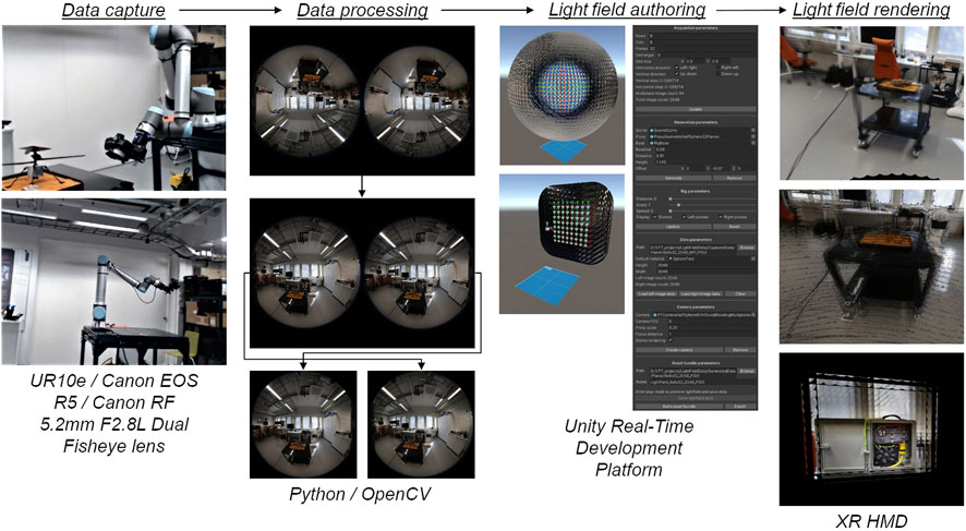
FIGURE 1. Main functionalities of immersive light field system (left: image capture with a robotically controlled camera; middle left: rotating, splitting, and trimming captured images; middle right: recreating camera positions to generate and export light fields; right: rendering light fields in XR HMD). Created with Unity Editor®. Unity is a trademark or registered trademark of Unity Technologies.
The system includes the following:
1) Data capture: client and server capture software controlling a Canon EOS R5 camera with a dual fisheye lens attached to the UR10e robot arm.
2) Data processing: collection of Python scripts for batch image processing using OpenCV and neural network for depth generation (MiDaS).
3) Light field authoring: Unity Editor project for light field generation and asset bundle exporting
4) Light field rendering: Unity Engine components and computation of ray tracing shaders for rendering light fields of different types.
The light field data capture for an immersive light field system was carried out with a single robotically controlled camera equipped with a dual fisheye lens (Figure 2). This approach allows capturing images for the left and right eyes simultaneously for stereoscopic rendering and controlling the number of pictures taken, together with capturing the volume, shape, and size. Another argument in favor of robotically controlled cameras in space exploration tasks is that space stations or planetary rovers are usually equipped with a robot arm to which a camera can be attached (the European robotic arm for an ISS and the robotic arm of the Curiosity rover). On the other hand, for sparse datasets and light field video capture, a multi-camera rig will be more suitable.
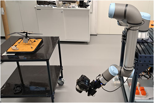
FIGURE 2. Planar light field data capture (left: engineering test POI/planetary drone crash site; right: a VR180-capable camera attached to UR10e robot arm).
A digital camera with a dual fisheye lens capable of producing VR180 videos was selected not only for its stereo capabilities but also because it is possible to simplify the process of 3D reconstruction by using texture projection onto a half-sphere proxy object, which later will be crucial for light field rendering. Capture by the conventional monocular lens with a narrow field of view (FOV) was tested as well.
The main implemented features include the following:
• Server application controlling image acquisition process
⁃ Amount of pictures and capture volume size can be set as parameters
• Client application controlling a robot arm
⁃ Different capture patterns for planar and panoramic light fields
• Planar light field captured by using a flat grid pattern
⁃ A 32 × 32 square flat grid pattern with a side length of 1 m
⁃ The total photo count is 1,024 (every ∼3.5 cm)
⁃ The capture time is less than 1 h
• Panoramic light field captured by using a spherical pattern
⁃ 30 × 72 spherical pattern with a diameter of 1.7 m
⁃ The total photo count is 2,160 (every 5°)
⁃ The capture time is almost 2 h
• Telegram bot reporting data capture progress
• Camera API used for synchronized remote shutter release (over wireless networks)
• Capture failure prevention mechanism (ensuring that images are taken)
• Captured images are uploaded to storage after the process is completed
Choosing the dataset size and sampling rate is always a compromise among data size, capture time, and desired light field quality. In the case of the immersive light field system described in this paper, the sampling rate directly contributes to the smoothness of interpolation between captured images and how wide the focusing range is. It would be possible to raise the sampling rate of the planar light field by 1.5, capturing the 46 × 46 dataset and bringing capture time to around an hour before hitting the current GPU memory limit, but better results could probably be achieved by moving the capture rig closer to the POI.
To satisfy the sub-objective of the project, other types of immersive data (360° photos and point clouds) were captured as well. For capturing the 360° photos, a Theta Z1 camera was used. It was placed on the tripod at a distance of 1.75 m from the floor to simulate the average person’s height, and a single 360° picture was taken at the same position as the panoramic light field was captured. Colored point clouds were captured using the Trimble X7 laser scanner. The data capture process was carried out from two different positions, and the data were combined afterward. The process was repeated for each POI. The resulting colored point clouds were processed with Pixyz Plugin for Unity and exported as ready-to-use packages. Those packages included a point cloud, color information, all necessary shaders, and a simplified collider mesh generated from the point cloud data.
The collection of data processing scripts is implemented to perform the following steps (Figure 3):
1) Image rotation
2) Splitting the stereo image into left and right eye images
3) Swapping left and right eye images
4) Trimming
5) Masking
6) Resizing
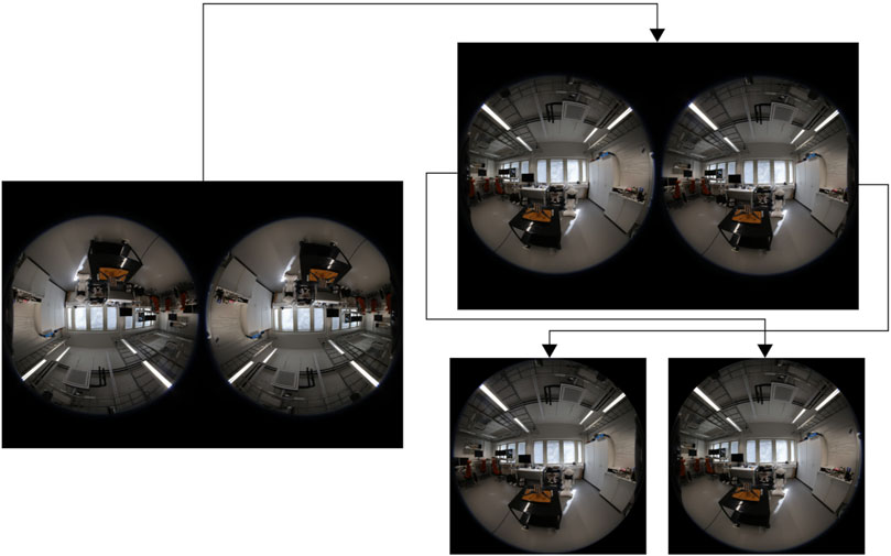
FIGURE 3. Data processing workflow (left: original image from VR180 camera; top right: image rotated by 180° to compensate for camera orientation; bottom right: rotated image split into two, and left and right parts are swapped to match lens placement).
First, the camera has to be mounted on the robot arm end effector upside down to bring it as close as possible to the robot arm’s axis of rotation and centered to remove the offset. This means that every image has to be rotated by 180° in order to bring it back to the correct orientation. Then, each image has to be split into left and right parts for each eye. As the original images from the dual fisheye lens have the left part on the right side, it is necessary to swap the images after splitting. Next, those images have to be trimmed down to bring them to a 1:1 aspect ratio as they are going to be used as textures. After that, a round mask is applied to each image in order to cover the edges and remove unused pixel data (light bleed from the lens). Finally, images are resized batch-wise to the target texture resolution (2,048 × 2,048 pixels).
For multiplane planar light fields, relative depth maps are generated using PyTorch and MiDaS. Then, from each grayscale depth map, 32 binary depth masks are generated. They are applied to each processed source fisheye image in order to generate 32 image planes. Each image plane has a black background instead of a transparency channel to sort out meaningful pixel data, so the textures will occupy less video memory during the rendering process (using three channels instead of four). After image processing, the texture files for the left and right eye are archived and uploaded for the authoring process.
As for the 360° pictures, no additional processing was needed. The Theta Z1 camera produces 8 K photos in an equirectangular format, which can be used directly with Unity Engine’s unlit shader. Colored point clouds were processed in Pixyz Plugin for Unity Engine and then exported as prefabs containing point cloud data split to multiple meshes, materials with a special shader to show mesh vertices as points, and a single simplified collider mesh.
The light field authoring process was performed inside the Unity Real-Time Development Platform environment (Figure 4). Most of the work was performed in the editor mode, whereas light field preview and data saving were available in the play mode. The asset bundle generation feature allows exporting the light field in a format with added compression which is convenient for sharing. Light fields are exported separately for each eye and take slightly more space on a disk than just the photos they were generated from. For example, a 32 × 32 planar stereoscopic light field composed of 1,024 photos will take ∼1.5 GB space on a disk.
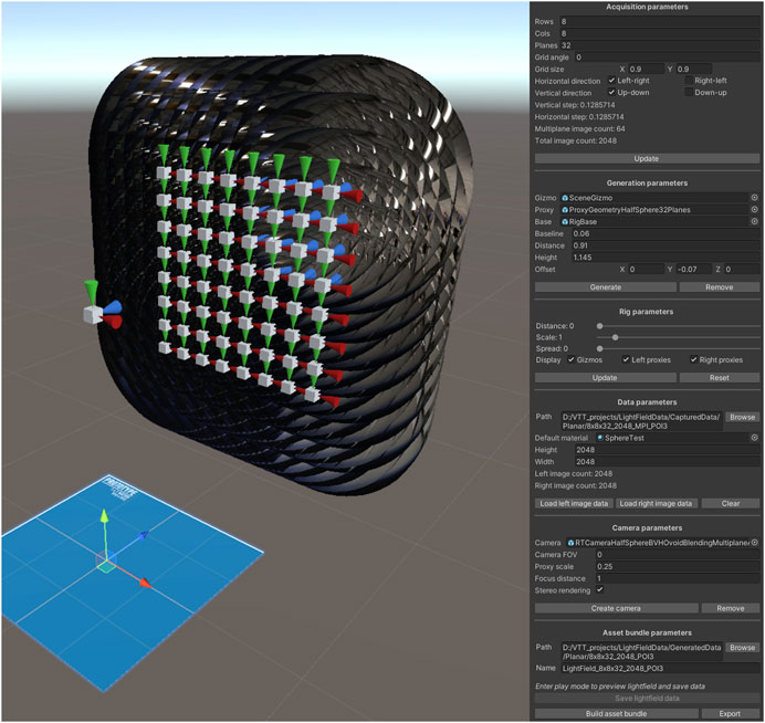
FIGURE 4. Light field authoring environment (left: visualization of recreated camera positions; right: editor script interface for light field generation and export). Created with Unity Editor®. Unity is a trademark or registered trademark of Unity Technologies.
Exported light fields can be used in the new scene in the following manner: first, the XRLightFieldCameraRig prefab is placed in the scene; next, the path to a light field file is specified in the master component for the left and right light field cameras; finally, light field camera parameters such as zoom, FOV, and focus distance are specified. The path to a light field file can be relative (if a light field file is placed in the StreamingAssets folder inside the project) or absolute (if a light field is placed somewhere on a disk). Light fields start loading automatically when the scene is first displayed during the application’s runtime.
The light field authoring process was performed as follows:
• The authoring process relies on the reconstruction of spatial relationships between camera positions.
⁃ By specifying pattern parameters and amount of photos, it is possible to generate a virtual representation of the real capture rig spatial characteristics.
⁃ Different proxy geometry prefabs can be selected based on the light field type.
⁃ The rig can be previewed in the editor mode to verify that camera positions are correct.
• Processed image data can be loaded from the disk.
⁃ Each image is loaded to CPU memory as a compressed texture.
⁃ Left and right eye data are loaded separately for the garbage collector to work properly.
⁃ Textures are applied to proxy geometry materials.
• A stereoscopic light field camera rig is created.
⁃ Proxy textures and positions are stored as the camera’s master parameters.
⁃ Light field focus and proxy scale parameters can be set as well.
• Light field data are generated, viewed, and saved in the play mode.
• Asset bundle for light field data is generated in the editor mode.
• Light field asset bundle can be exported to the specified path on the disk.
Light field rendering (Figure 5) is a non-trivial problem. As the amount of light rays captured by the camera across a dense dataset is very large (around 4.3 billion for a 32 × 32 pattern planar light field), real-time rendering is only possible if the problem is inverted and each pixel of the resulting image is traced instead of the captured light rays.
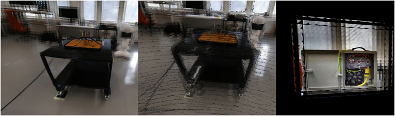
FIGURE 5. Planar light field rendering results (left: light field captured with a dual fisheye lens; middle: light field composed of multiplane images; right: light field captured with a non-fisheye lens). Created with Unity Editor®. Unity is a trademark or registered trademark of Unity Technologies.
This process is performed using the ray tracing method in a compute shader. Shader kernels run in parallel on the GPU, so modern hardware can achieve real-time performance while operating on ray tracing primitives. It is possible to perform ray-plane or ray-sphere intersection tests in large enough quantities to cover the dataset size, but intersecting many triangle meshes generated by the 3D reconstruction process is still not fast enough. This is where the VR180 format comes in handy: by projecting a fisheye image as a texture onto a half-sphere ray tracing primitive placed at the capture position, it is possible to achieve results similar to 3D reconstruction without performing ray–triangle intersection checks. Moreover, this placement means that for the disk-blending method, the camera ray cannot miss the half-sphere unless it is scaled smaller than the blending object. This is not the case with non-fisheye lenses and quads as proxies; therefore, this is another advantage of a VR180-capable camera.
The disk-blending method was implemented similarly to the “Welcome to Light Fields” application (Overbeck et al., 2018b). The disk is effectively an oval shape with four half-axes of different lengths, which extend to the center of the neighboring disk for optimal capture volume coverage. Each disk has one or multiple (in the case of MPIs) half-sphere primitives assigned, onto which the original image texture is projected. Each disk’s position and orientation correspond to the camera lens pose during capture, and the half-sphere primitive is centered around the disk, with its center aligned to the disk’s normal vector. The disks are mainly used for two purposes: as a camera ray target during the initial intersection check and to assign a weight to the color of the following intersection with a half-sphere primitive.
The intersection color weight is a floating-point value in a range from 0 to 1. As this value gradually drops further, the intersection is from the center of the disk. Each camera ray can intersect up to four disks, accumulating weighted color values. Those weighted color values are summed up and divided by the sum of their weights during the final blending process.
It is worth mentioning that the disk-blending method works well for rendering multiple light field types. For the light field captured with a fisheye lens, each blending disk is placed at the original capture position, and the half-sphere proxy is wrapped around it. A multiplane light field setup is similar; each image plane is projected on its half-sphere but is scaled up depending on its position in the depth stack to provide a depth-based parallax. Last, the non-fisheye light field uses a quad proxy, which is placed at a focus distance from the blending disk and is scaled to focus the light field. The disadvantage of this setup is that the camera ray misses the proxy quite often due to its placement, significantly limiting viewing angles.
In general, the performance of the light field renderer depends on the number of photos used to generate the light field and the rendering target resolution (screen or texture). For example, using Valve Index headset screen resolution as a rendering target, a 30 × 72 pattern panoramic light field can be rendered in ∼30 FPS on RTX 2080Ti GPU, whereas a 32 × 32 pattern planar light field will be rendered in ∼45 FPS. Smaller light fields can achieve the target SteamVR performance of 90 FPS. Using an acceleration structure lessens the impact of the dataset size on the rendering performance.
On the other hand, the quality of light field rendering is defined by its sharpness and precision of convergence. Sharpness depends on the initial image texture resolution and density of the dataset, whereas the spacing between adjacent camera positions influences the precision of the light field convergence. Figure 6 shows the light field sharpness.
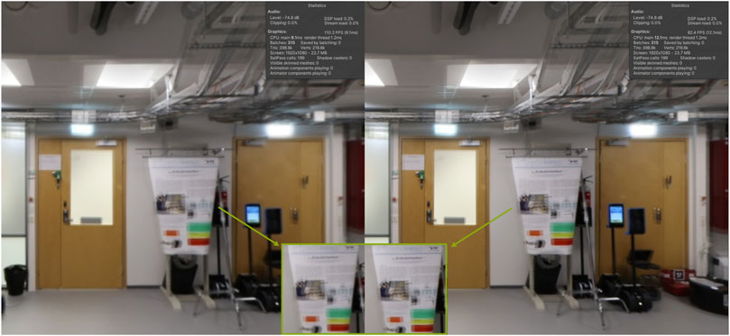
FIGURE 6. Panoramic light field sharpness comparison: 1,024 × 1,024 pixels resolution (left) vs. 2,048 × 2,048 pixels resolution (right). Created with Unity Editor®. Unity is a trademark or registered trademark of Unity Technologies.
As can be seen from Figure 6, increasing the image texture size slightly improves the light field sharpness, and this effect is more noticeable in the VR headset. There is a slight performance drop, but more important is the fact that going up to the next texture size will require 4 times more video memory, which is why, at least in this project, textures with a resolution of 2,048 × 2,048 pixels were used.
Next, the precision of the light field convergence comparison is shown in Figure 7. For the light field on the left, pictures were taken every 10° (making it 36 pictures per row), and for the light field on the right, pictures were taken every 5° (72 pictures per row). Doing this effectively not only doubles the light field data size but also significantly increases the convergence precision and helps to reduce ghosting artifacts. In general, rendering a twice larger light field has a big impact on the performance, but is worth the sacrifice as it makes it possible to read the large enough text (like handwriting on a whiteboard). It is worth noting that although ghosting in the highlighted area can be improved by raising the sampling rate, it cannot be completely eliminated as camera placement error contributes to it. In the panoramic light field, the error caused by the camera offset is visible mostly on the poles of the volume as the camera trajectory gets tighter.
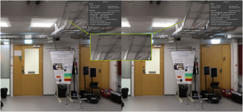
FIGURE 7. Panoramic light field convergence comparison: 10° capture spacing (left) vs. 5° capture spacing (right). Created with Unity Editor®. Unity is a trademark or registered trademark of Unity Technologies.
The planar light field does not suffer from camera offset because the data capture is performed using a flat grid pattern and there is no rotation, so it has fewer ghosting artifacts. The ghosting in the planar light field comes from the focusing process; just like an unfocused photograph gets blurry, the unfocused light field diverges, which results in seeing individual images and producing a ghosting effect. When focusing on the background, foreground objects will diverge, and when focusing on the foreground, the background will do the same.
Overall, the light field system’s rendering implementation has the following features:
• Light field rendering is performed by the compute shader.
⁃ Ray tracing is used with primitive objects (planes, quads, disks, and spheres).
⁃ An acceleration structure is implemented to speed up the rendering (bounding volume hierarchy).
⁃ The disk-blending method is used to generate new perspective views from existing ones.
• Different proxy objects are used:
⁃Half-sphere
⁃Multiplane half-sphere
⁃ Quad
• Multiple ways exist to render a light field:
⁃ To screen
⁃ To 180° fisheye texture
⁃ To 360° equirectangular texture
• The light field can be refocused by changing the proxy scale.
• The light field can be zoomed in by scaling the proxy texture (planar light field only).
To evaluate the immersive light field system, three possible test use cases were selected: geological test (water site), archeological test (fossil site), and engineering test (crash site). For each test use case, its own POI was created (Figure 8).
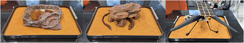
FIGURE 8. POIs for the test cases (left: water site; middle: fossil site; right: crash site).
After all the data were captured for each POI (360° pictures, point cloud, and planar and panoramic light fields), immersive virtual scenes were created for each POI. The test application used OpenVR API to be compatible with multiple SteamVR headsets and included interaction profiles for both Valve Index and HTC Vive controllers.
Each test was performed across multiple scenes:
• Hub scene (starting scene): the user can select 1 out of 3 POIs.
• Point cloud scene (LIDAR scan): the user can inspect the point cloud and select a 360° picture or light field for further inspection, or choose to go back to the hub scene.
• 360° photo scene: the user can inspect the 360° photo or go back to the point cloud scene.
• Panoramic light field scene: the user can inspect the panoramic light field or go back to the point cloud scene.
• Planar light field scene: the user can inspect the planar light field or go back to the point cloud scene.
Test scenes used standard SteamVR interactions: teleportation with parabolic arc, snap turn, and object grab:
• To teleport, the user should tilt the analog stick forward (Valve Index controller) or press the trigger (HTC Vive controller), point a parabolic arc to the floor, and release the analog stick or trigger.
• To snap turn, the user should quickly tilt the analog stick to the left or right and release (Valve Index), or press the touchpad near the left or right edge (HTC Vive).
• To grab objects, the user should close the hand around the controller (Valve Index) or press the grip buttons (HTC Vive).
To change a scene, the user should grab a sphere and put it on their head as if they are trying to look through it. The application will display hints on the controllers and may ask to teleport back to the center of the tracking space for the light field scene while the light field is loading (Figure 9).
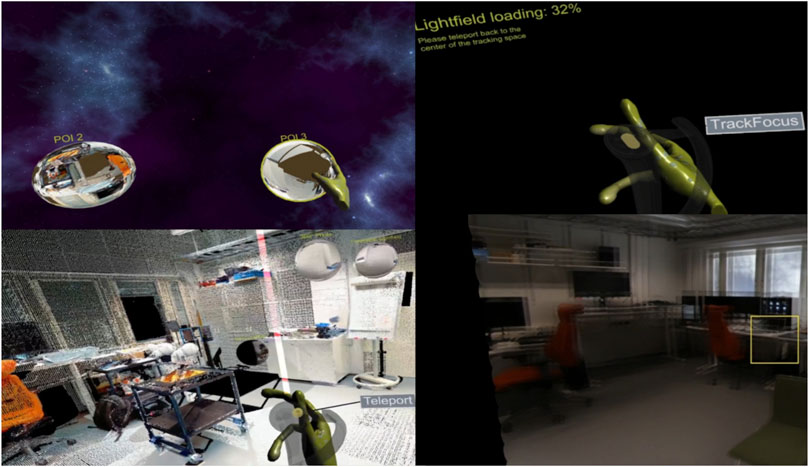
FIGURE 9. Various test application scenes (top left: hub scene; bottom left: point cloud scene; right: panoramic and planar light field scenes). Created with Unity Editor®. Unity is a trademark or registered trademark of Unity Technologies.
The only interactions in the test application scenes were teleportation and scene selection, whereas light field scenes had an option for light field refocusing.
Light fields have a focus property like a standard photo camera:
• To change a focus distance, the user should press the A or B buttons (Valve Index) or click the touchpad near the top or bottom edge (HTC Vive).
• To autofocus, the user should press the trigger (Valve Index) or click the center of the touchpad (HTC Vive).
• To scroll through a focus distance, the user should swipe the touchpad up and down (on both Valve Index and HTC Vive controllers).
Autofocus depends on sampling the screen near the middle of the user’s view, but without eye-tracking implementation, it is not very precise. For the user test, the autofocus option was disabled in the test application. The suggested way to refocus a light field was to change focus distance with the A/B buttons (Valve Index) or by clicking the trackpad (HTC Vive).
The main objective of the geological test is to detect POI features using the light field properties. The secondary objective is to evaluate how different media (point cloud and 360° picture) are comparable to the light field (Figure 10).
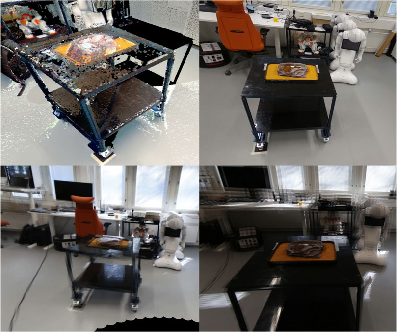
FIGURE 10. Geological test POIs in different media (top left: point cloud; top right: 360° picture; bottom left: panoramic light field; bottom right: planar light field). Created with Unity Editor®. Unity is a trademark or registered trademark of Unity Technologies.
For this test, the POI includes multiple elements: ceramic rock with realistic texture, 3D-printed trilobite fossils, and water (or ice) imitated by clear epoxy. Water can be detected from the dynamic reflections captured by the light field data and from the refraction of light, which can be observed from multiple points of view.
During the test, the expert end-user was asked to observe the POI using all available data and see if it was possible to detect the presence of water and guess the geological composition of the rock.
The main objective of the archeological test is to detect POI features using the light field properties. The secondary objective is to evaluate how different media (point cloud and 360° picture) are comparable to the light field (Figure 11).
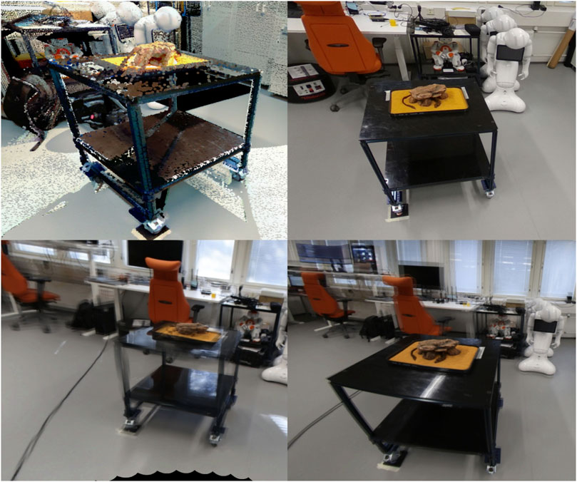
FIGURE 11. Archeological test POIs in different media (top left: point cloud; top right: 360° picture; bottom left: panoramic light field; bottom right: planar light field). Created with Unity Editor®. Unity is a trademark or registered trademark of Unity Technologies.
The POI for the archeological test is similar to the one described earlier, but in this case, the 3D-printed fossil has more details and a unique texture. The POI is set up in a particular manner, so by changing the perspective, it should be possible to better understand shapes and patterns. From certain positions, light will shine through the gaps in objects showing separation; for example, it should be visible that the fossil is placed under the rock and is not embedded in it.
During the test, the expert end-user was asked to observe the POI using all available data and see if it was possible to identify fossils in the scene and understand their spatial properties.
The main objective of the engineering test is to detect POI features using the light field properties. The secondary objective is to evaluate how different media (point cloud and 360° picture) are comparable to the light field (Figure 12).
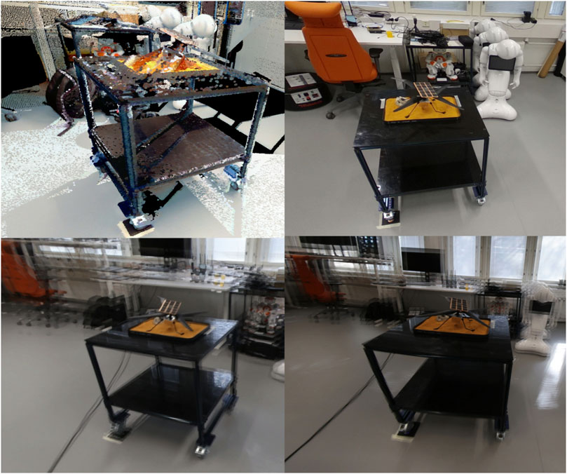
FIGURE 12. Engineering test POIs in different media (top left: point cloud; top right: 360° picture; bottom left: panoramic light field; bottom right: planar light field). Created with Unity Editor®. Unity is a trademark or registered trademark of Unity Technologies.
The POI for the engineering test is slightly different. It contains a 3D-printed model of a planetary helicopter drone, which crashed during the landing. It has noticeable damage: a broken landing gear and a bent rotor blade. By observing the POI from different perspectives in a light field, it should be possible to see that the reason behind the damage is a small rock in which the drone had landed on.
During the test, the expert end-user was asked to observe the POI using all available data and detect the amount of damage and what could be the possible cause of it.
The user evaluation of the immersive light field system was realized with potential end-users of the system. The evaluation was conducted in the EAC premises in Cologne on 24 May 2023. The main goal of the user evaluation was to evaluate the usefulness and usability of the light field system for the feasibility and further development of the system. The evaluation methods included interviews, observations, and questionnaires.
The light field system was tested by using an HTC Vive Pro 2 head-mounted display (HMD), four Valve Index tracking base stations (lighthouse tracking system), and Valve Index controllers.
The light field system application consisted of multiple scenes for users to explore:
• Hub scene (starting scene): the user can select 1 out of 3 POIs (points of interest).
• Point cloud scene (LIDAR scan): the user can inspect the point cloud and select a 360° picture or light field for further inspection, or choose to go back to the hub.
• 360° photo scene: the user can inspect a 360° photo or go back to the point cloud scene.
• Panoramic light field scene: the user can inspect the panoramic light field or go back to the point cloud scene.
• Planar light field scene: the user can inspect the planar light field or go back to the point cloud scene.
The evaluation participants represented potential system end-users from the EAC (Figure 13). The total number of participants was three (N = 3). During the test, the participants were focusing on the most relevant test use cases/POIs based on their backgrounds. The available POIs were as follows:
• POI 1: geological test/water site.
• POI 2: archeological test/fossil site.
• POI 3: engineering test/crash site, planetary drone (helicopter) crash site.
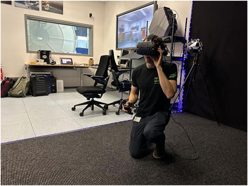
FIGURE 13. Test participant interactions with the light field system during the usability evaluation at the EAC premises.
Project members responsible for the development set up the light field system application and provided guidance and support during the evaluation.
Methods for collecting data from the test users were as follows:
• System usability scale (SUS) questionnaire
• Usefulness questionnaire
• Semi-structured interview focusing on the usability and usefulness of the system
• Observation by the evaluation organizers
The test users performed the test individually according to instructions from the test organizers. After the test, the users filled in the questionnaires and then participated in an interview. The users also commented on the system during the test performance.
Test users were asked to describe their immediate reactions to the light field system at the beginning of the interviews. Both positive and negative descriptions emerged.
The positive descriptions included interesting, eye-opening, intriguing, six degrees of freedom (6DOF), and promising.
The system was described as interesting because it provides more possibilities than, for example, a 360° picture. Eye-opening and intriguing were used to describe the experience that the user understood and imagined during the test, and what can be done and observed with different scenes. Six degrees of freedom refers to the idea that the user can move freely forward/backward, up/down, and left/right in the 3D space to explore the POI.
Negative or neutral descriptions included quite early/immature, slightly irritating, and distorting.
The system was described as immature and having some distortions because of the early phase of development and some usability issues. It was, for example, hard to get the needed information because of resolution, focus, and frame rate (etc.). The room-scale VR system (head-mounted display and tracked hand controllers) is slightly cumbersome to wear, especially for first-time users. The hub scene uses VR-specific interaction - the user should pick up the orb and put it on their head to enter the next scene, so it has a bit of a learning curve.
The users suggested the following benefits and aspects in different test use cases (POIs):
• Each system scene provided something useful: the point cloud had the best sense of scale, the 360° picture had the best resolution (could be still improved), and the planar light field provided a sense of reality which other scenes did not provide, mostly the surface textures.
• The combination of water and colors beneath the water was the most interesting feature.
• Planar light field was more useful in this use case, whereas the panoramic light field did not give as much information on the specific object in this case.
• Ideally, the goal is to put the user into the environment to get the user as close to reality as possible. Everything that helps in this is useful.
• This system could be used for training people as well.
• The benefit depends on what the user is looking for: the point cloud does not have much use, the 360° picture is good for overview when looking for interesting objects, and the light field is good for specific questions, especially for fossils when one does not first know whether it is a fossil or not. It is better than the normal picture, as one can see the surface texture better. The light helps to see. When looking for possible POIs, the light field can be better than the normal picture. Differences in colors are interesting.
• Best combination of scenes: 360° is good for a preliminary survey, and then light field scenes can be used for more details.
• Sometimes, everything cannot be seen in a 360° picture, a light field can bring an added value; it would be easier to see and identify fossils, and analyze them more efficiently.
• The best combination would be a point cloud with a light field.
• The 360° picture scene could be removed. In this case, it is not very useful, but for geologists, it can be more useful.
• Outside-in view, where the user can rotate around the POI could be ideal.
Several improvement suggestions emerged from the interviews and observations. The following list summarizes the suggestions:
• The user should be able to tailor the user interface with POIs (currently three “bubbles”) based on personal preferences, especially if there are more than three POIs.
• User interface now forces the user always to go back to the point cloud scene in order to change between the scenes. This could be more flexible.
• Outside-in view could be useful. The user could rotate around POIs.
• Image controls should be added: brightness, contrast, saturation, grayscale, etc. The resolution could be improved if possible.
• There should be some sort of a measuring tool to understand the scale of objects.
• In a panoramic light field scene, it is not always useful to see the surroundings when looking at the POI. The user should have the option to choose the view.
• The light field should be better adjusted to the person’s field of vision; information was presented too low.
• The POI should be closer to the camera, with a possibility to zoom closer to the POI.
• Focusing could be generally improved; it should give more control to the user.
• Autofocus by exploiting gaze tracking should be used.
• Manual focusing should be performed via dedicated buttons.
• Autofocus and focus tracking should be separated from the manual focus controls.
• The system should be tested with normal cameras.
• System features should be tested and presented in a more realistic environment, for example, outside and not in the laboratory (as was the case in this user test).
• Suggestion for the next test task: the user should try to find the POI in the specific environment with the help of the system.
In summary, the users considered the system as potentially useful for their purposes. The different scenes provided by the system and the combinations of scenes can bring added value when looking for detailed information about the object and environment. The light field scenes have the potential to expand the current possibilities, compared, for example, with 360° pictures.
The low technology readiness level expectation of the XR-system prototype was understood and accepted by the users at this stage of development. Various usability and technological improvements are needed to make the system more useful and feasible.
The SUS questionnaire includes 10 items (statements) to be answered. The SUS is a tool for measuring both usability and learnability. The SUS scores calculated from individual questionnaires represent the system usability. Scores for individual items are not meaningful on their own (Brooke, 1996).
SUS scores have a range of 0–100. According to validation studies (Bangor et al., 2009; Brooke, 2013), the SUS score starting from 68 to 70 represents the level of acceptable system usability. The suggested acceptability ranges are as follows: 0–50, not acceptable; 50–70, marginal; and 70–100, acceptable. Table 1 presents the SUS scores from the test users.

TABLE 1. System usability scale (SUS) scores.
The SUS score average of 82 indicates acceptable system usability, as well as all the individual scores. It was however mentioned in the interviews that usability could be improved in various ways. The quite high SUS scores reflect the fact that users understood that the system is still an early prototype with low technology readiness expectations, and the usability is sufficient at this stage of development.
The usefulness questionnaire was filled in after filling in the SUS questionnaire. The questionnaire was based on technology acceptance model (TAM) questionnaires (Lewis, 2019), especially on the part related to perceived usefulness. The users were asked to think of the potential of the system in their work while filling in the questionnaire. Table 2 presents the usefulness questionnaire results from the test users.
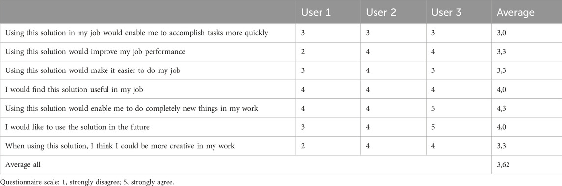
TABLE 2. Usefulness questionnaire results.
According to the results, the system would enable the users especially to perform new kinds of things in their work and the system would be generally useful. The effect on doing tasks more quickly or easily would be moderate or insignificant. Some notable variation between the individual answers was related to increasing creativity and improving job performance (variation from 2 = disagree to 4 = agree).
The users considered the system as potentially useful for their purposes. The different scenes provided by the system and the combinations of scenes can bring added value when looking for detailed information about the object and environment. The light field scenes have the potential to expand the current possibilities, compared, for example, with 360° pictures.
Various usability and technological improvements will be needed to make the system more useful and feasible. It was furthermore pointed out, partly beyond the actual usability evaluation, that if there is too much unbalance between the costs of the system and the gained results, it would possibly prevent the usage of the system.
During the development of the system, usefulness of various approaches to light field generation was investigated. For example, classic 3D reconstruction methods with calibrated stereo cameras proved not to be suitable for light field generation. It does work well in feature-rich environments, but the AI-based approach shows better results for depth estimation in featureless indoor spaces. The process of calibrating an ultra-wide FOV dual fisheye lens was time-consuming and prone to errors, and the resulting point clouds and meshes were too flat to be useful. Only a fraction of image pixels provided proper absolute depth values.
Another problem with the 3D reconstruction process is the ray tracing shader performance. Real-time ray tracing works fast enough with primitive objects but is still too slow to trace polygonal meshes. Rendering quad meshes was fast enough but did not have any advantages over similar ray tracing primitives, and rendering detailed half-sphere meshes was very slow (close to ∼3 FPS at 128 × 128 pixels target resolution). Using the stereoscopic VR180 format eliminated the need to use meshes in the ray tracing shader altogether.
Finally, after rendering light fields of different sizes and resolutions, the following correlations were discovered: even the distribution of capture positions improves light field convergence precision, more capture positions lead to smoother transitions between generated perspectives, and higher resolution of images improves light field sharpness.
The main goal of the project was to evaluate the feasibility of the system that was present in the early phase of development. Rather than producing highly generalized results on the use of light fields, the user study aimed to provide opinions and insights on system’s suitability for end-users’ specific work and produce ideas for further development. As the system was an early prototype, the results are preliminary by nature. The specific test use cases were designed to simulate test users’ work, allowing them to evaluate the system in their own specific work tasks. The evaluation results are somewhat limited by these specific use cases. The questionnaire results do not have statistical significance due to the limited number of test users, but they provide insights on feasibility and usefulness combined with qualitative interview results.
Generally, the users evaluated the light field system as potentially useful for their work. The different scenes provided by the system (point cloud, 360° picture, and light fields) can serve different purposes, and each can be beneficial depending on the goal and task. The light field scenes can bring added value, for example, when the user wants to see more details.
It was recognized and understood that the system was an early prototype with quite low technology readiness level expectations. This report presents several suggestions and viewpoints for improving the usability of the light field system.
Among the possible future extensions of the immersive light field system is a mobile capture rig based on a Boston Dynamics Spot robot. Capturing real points of interest in nature from a remotely controlled robot platform could bring additional value to the system, especially in hazardous environments. A Spot robot has a wide array of sensors, can carry a LIDAR 360° camera, and should have an arm strong enough to carry a Canon camera.
Another interesting idea suggested during the user test was to perform an outside-in light field capture. This would be possible to implement by using the current UR10e setup with an additional rotating table. The light field volume will have a dome shape, and the robot arm only has to capture pictures along the half-arc. The challenge would be to synchronize the table rotation to the capture software; otherwise, the changes to the project are minimal.
Panoramic light field capture could be improved by solving the circle packing problem on a spherical capture volume surface. This will help to keep the sampling rate constant between the equator and poles of the capture volume, improve the blending precision, and reduce the dataset size. Changing the diameter of the circles will control the light field sampling rate. Because circle positions will not be known beforehand and are unique for each sampling rate value, camera positions should be generated and sent to a robot arm, making data capture a part of the light field authoring process. Multi-view feature detection and matching could be used for tracking real-world camera positions, which in turn could be used in a feedback loop to improve virtual capture rig precision.
Finally, the light field autofocus system can show some improvement. One possible solution could be to use a mesh collider built from the LIDAR scan underneath the light field for camera ray casts. As the light field focusing is carried out by changing the per-view proxy object scale, by establishing a relationship between the absolute depth and the scale of the proxy, it should be possible to calculate a focal length value. This will allow us to perform autofocus immediately instead of changing it in incremental steps. Another improvement in light field focusing could be the use of the ray tracing depth of field (DOF) effect. By using a focal length value and selecting aperture size, it should be possible to blur out-of-focus objects and hide the ghosting effect. This process will negatively affect the real-time performance and produce noise, so a high sample per pixel (SPP) rate and additional filtering may be required.
Alternatively, eye-tracking could be used with the current autofocus code in order to improve its performance. A color variance map built at the blending stage could also be used for blurring the out-of-focus objects. This will be less precise than a ray tracing DOF effect but should be faster and more suitable for real-time applications.
The raw data supporting the conclusion of this article will be made available by the authors, without undue reservation.
The studies involving humans were approved by VTT’s Ethical Committee: Matti Karhunen (chair), Heli Helenius, Veikko Ikonen, Anneli Ritala, Jarmo Siivinen, and Satu Streng. The studies were conducted in accordance with the local legislation and institutional requirements. The participants provided their written informed consent to participate in this study. Written informed consent was obtained from the individual(s) for the publication of any potentially identifiable images or data included in this article.
VG: conceptualization, software, visualization, writing–original draft, methodology, and writing–review and editing. TK: writing–review and editing, investigation, formal analysis, methodology, validation, and writing–original draft. PT: writing–review and editing, investigation, and software. JK: conceptualization, software, writing–review and editing, methodology, and investigation. KH: methodology, writing–review and editing, conceptualization, funding acquisition, project administration, and supervision.
The author(s) declare financial support was received for the research, authorship, and/or publication of this article. This study has been funded by the European Space Agency under contract 4000137955/22/NL/GLC/ov “Light field-enhanced immersive teleoperation system for space station and ground control.” The authors declare that this study received funding from VTT Technical Research Centre of Finland Ltd.
Authors VG, TK, PT, JK, and KH were employed by VTT Technical Research Centre of Finland Ltd.
The authors declare that this study received funding from VTT Technical Research Centre of Finland Ltd. VTT Technical Research Centre of Finland Ltd has designed and conducted the study, has funded the writing of this article, and has covered the open access publication fee.
All claims expressed in this article are solely those of the authors and do not necessarily represent those of their affiliated organizations, or those of the publisher, the editors, and the reviewers. Any product that may be evaluated in this article, or claim that may be made by its manufacturer, is not guaranteed or endorsed by the publisher.
Bangor, A., Kortum, P., and Miller, J. (2009). Determining what individual SUS scores mean: adding an adjective rating scale. J. Usability Stud. 4 (3), 114–123. doi:10.5555/2835587.2835589
Brooke, J. (1996). “SUS: a ‘quick and dirty’ usability scale,” in Usability evaluation in industry. Editors P. W. Jordan, B. Thomas, B. A. Weerdmeester, and I. L. McLelland (London, UK: Taylor and Francis Ltd).
Brooke, J. (2013). SUS: a retrospective. J. Usability Stud. 8 (2), 29–40. doi:10.5555/2817912.2817913
Broxton, M., Busch, J., Dourgarian, J., DuVall, M., Erickson, D., Evangelakos, D., et al. (2020b). “DeepView immersive light field video,” in ACM SIGGRAPH 2020 Immersive Pavilion (SIGGRAPH '20), New York, NY, USA (Association for Computing Machinery). New York, NY, 1–2. Article 15. doi:10.1145/3388536.3407878
Broxton, M., Busch, J., Dourgarian, J., DuVall, M., Erickson, D., Evangelakos, D., et al. (2019). “A low cost multi-camera array for panoramic light field video capture,” in SIGGRAPH Asia 2019 Posters (SA '19), New York, NY, USA (Association for Computing Machinery). New York, NY, 1–2. Article 25. doi:10.1145/3355056.3364593
Broxton, M., Flynn, J., Ryan, O., Erickson, D., Hedman, P., Duvall, M., et al. (2020a). Immersive light field video with a layered mesh representation. ACM Trans. Graph. 39, 4-15. Article 86 (August 2020). doi:10.1145/3386569.3392485
Debevec, P., Yu, Y., and George, B. (1998). Efficient view-dependent image-based rendering with projective texture-mapping. Technical Report. USA: University of California at Berkeley.
Deng, N. (2021). FoV-NeRF: foveated neural radiance fields for virtual reality. arXiv e-prints. doi:10.48550/arXiv.2103.16365
Dinechin, G. D. d., and Paljic, A. (2020). “From real to virtual: an image-based rendering toolkit to help bring the world around us into virtual reality,” in 2020 IEEE Conference on Virtual Reality and 3D User Interfaces Abstracts and Workshops (VRW), Atlanta, GA, USA, 348–353. doi:10.1109/VRW50115.2020.00076
Goriachev, V., Kuula, T., Tikka, P., Karjalainen, J., and Helin, K. (2023). LightSpace: lightfield-enhanced immersive teleoperation system for Space. Zenodo. doi:10.5281/zenodo.10257355
Levoy, M., and Hanrahan, P. (1996). “Light field rendering,” in Proceedings of the 23rd annual conference on Computer graphics and interactive techniques (SIGGRAPH '96) (New York, NY, USA: Association for Computing Machinery), 31–42. doi:10.1145/237170.237199
Lewis, J. R. (2019). Comparison of four TAM item formats: effect of response option labels and order. J. Usability Stud. 14 (4), 224–236. doi:10.5555/3542805.3542809
Mildenhall, B., Srinivasan, P. P., Tancik, M., Barron, J. T., Ramamoorthi, R., and Ng, R. (2020). NeRF: representing scenes as neural radiance fields for view synthesis. arXiv e-prints. doi:10.48550/arXiv.2003.08934
OTOY (2015). OTOY demonstrates first ever light field capture for VR. Available at: https://home.otoy.com/otoy-demonstrates-first-ever-light-field-capture-for-vr/(Accessed September 12, 2023).
Overbeck, R., Erickson, D., Evangelakos, D., and Pharr, M. M. (2018a). A system for acquiring, processing, and rendering panoramic LightField stills for virtual reality. Available at: https://www.youtube.com/watch?v=GnGqoRTZjWM.
Overbeck, R. S., Erickson, D., Evangelakos, D., and Paul, D. (2018b). “The making of welcome to light fields VR,” in ACM SIGGRAPH 2018 Talks (SIGGRAPH '18), New York, NY, USA (Association for Computing Machinery). New York, NY, 1–2. Article 63. doi:10.1145/3214745.3214811
Overbeck, R. S., Erickson, D., Evangelakos, D., Pharr, M., and Paul, D. (2018c). A system for acquiring, processing, and rendering panoramic light field stills for virtual reality. ACM Trans. Graph. 37, 1, Article 197 (December 2018), 15. doi:10.1145/3272127.3275031
Peret, L., Gasnault, O., Dingler, R., Langevin, Y., Bender, S., Blaney, D., et al. (2016). “Restoration of the Autofocus capability of the ChemCam instrument onboard the Curiosity rover,” in AIAA 2016-2539. SpaceOps 2016 Conference. doi:10.2514/6.2016-2539
Tucker, R., and Snavely, N. (2020). “Single-View view synthesis with multiplane images”. arXiv e-prints. doi:10.48550/arXiv.2004.11364
Unity (2017). Vision 2017 - unity + octane: the path to holographic cinematic rendering. Available at: https://www.youtube.com/watch?v=n9oILsWlW1U.
Keywords: light field, image-based rendering, virtual reality, extended reality, user experience, usability evaluation, space exploration
Citation: Goriachev V, Kuula T, Tikka P, Karjalainen J and Helin K (2024) Development and user evaluation of an immersive light field system for space exploration. Front. Virtual Real. 4:1294877. doi: 10.3389/frvir.2023.1294877
Received: 15 September 2023; Accepted: 22 December 2023;
Published: 22 January 2024.
Edited by:
Hai-Ning Liang, Xi’an Jiaotong-Liverpool University, ChinaReviewed by:
Jonathan Ventura, California Polytechnic State University, United StatesCopyright © 2024 Goriachev, Kuula, Tikka, Karjalainen and Helin. This is an open-access article distributed under the terms of the Creative Commons Attribution License (CC BY). The use, distribution or reproduction in other forums is permitted, provided the original author(s) and the copyright owner(s) are credited and that the original publication in this journal is cited, in accordance with accepted academic practice. No use, distribution or reproduction is permitted which does not comply with these terms.
*Correspondence: Vladimir Goriachev, dmxhZGltaXIuZ29yaWFjaGV2QHZ0dC5maQ==
Disclaimer: All claims expressed in this article are solely those of the authors and do not necessarily represent those of their affiliated organizations, or those of the publisher, the editors and the reviewers. Any product that may be evaluated in this article or claim that may be made by its manufacturer is not guaranteed or endorsed by the publisher.
Research integrity at Frontiers
Learn more about the work of our research integrity team to safeguard the quality of each article we publish.