 Felix Longge Michels
 Victor Häfner
- Smart Immersive Environments, Institute for Information Management in Engineering, Department of Mechanical Engineering, Karlsruhe Institute of Technology, Karlsruhe, Germany
Virtual engineering as a new working method in product development should make it much easier to validate the development progress and facilitate team communication. Work steps are brought forward and start with the virtual components instead of real ones. To validate mechanical and electrical CAD as well as programming, automated virtualization systems should create the virtual twin of the machine at the push of a button. For this purpose, generic intelligence is added to enable complex interactive virtual models that can be used for training, monitoring and many other applications. Advanced applications are for example training and support applications, especially in combination with augmented reality and remote collaboration. We propose a system that combines virtual reality, virtual engineering and artificial intelligence methods for the product development process. Geometry analysis algorithms are used to process mechanical CAD data and thus, for example, to automatically parameterize kinematic simulations. In combination with electrical CAD data and the simulations of electric circuits as well as the original machine program allow simulating the behavior of the machine and the user interaction with it. This article will describe the virtualization method in detail and present various use-cases in special machine construction. It will also propose a novel method to use causal discovery in complex machine simulations.
1 Introduction
Engineering machines is a dream at least as old as the ancient Greeks. Machines are a way to give us frail humans the power of many, maybe even of gods. They allow us to move heavy things with great speed, communicate with others far away in real time, fly to the skies and explore the depths of our oceans. To help design and build those machines with ever-growing complexity, sophisticated tools were invented. Then came automation and computing, they revolutionized the way we engineer machines by extending our hands and brains with computer aided design (CAD), machining tools and 3D printing just to name a few. Traditionally, the engineering domain is very fragmented, each subdomain using their own software ecosystems like mechanical CAD (MCAD), electrical CAD (ECAD), numerical simulations and programming. Communication between teams and disciplines is key to creating successful products. Virtual reality is the ideal technology to enhance the exchange of information and offer an environment to collaborate and validate planning data from CAD systems. Virtual reality in engineering (or Virtual Engineering) encompasses the whole product life cycle and supports it with a variety of applications like the design review during the product development process, production planning for manufacturing, training applications and many more. The concepts, methods and systems are well known for years, but struggle to get adopted, especially in small and medium-sized enterprises. More advanced applications are the training of workers for the configuration, operation and maintenance of products, often machines or production plants.
We will show alongside the use case of a virtual simulation for a tunnel boring machine (TBM) how the integration of such strategies as well as software and hardware in the loop can be deployed to generate an intelligent virtual twin. With the integration of the programming of the complete machine as a foundation of the virtual representation, the behavior of the virtual machine can replicate real world scenarios with highly customizable settings. The original TBM machine program runs on a programmable logic controller (PLC). Our virtual reality simulation of the TBM communicates with the PLC via the OPCUA protocol. The control panel is using the commonly used hardware-to-software communication ProfiNet. Currently, the simulator of the virtual tunnel boring machine is used for training new machine operators without the risks of endangering equipment and human safety and even offers the possibility to train for simulated critical failures.
The aim of this work is to give insights into current research and innovation that tackles the issues like CAD data integration and workflow automation, artificial intelligence (AI) supported model introspection to maximize added value and overall usability. The related works section will give an overview of available software solutions and current research activities in the domains described above. The implementation section presents our recent work in the field of virtual machine simulations, followed by the discussion and outlook section where we summarize our research and present our thoughts, ideas and plans on next steps towards the ideal virtualization system.
2 Related works
The relevant state of the art for this article, especially regarding virtual engineering, is structured as follows. First, it is important to get an overview of state-of-the-art design review tools, they are software products used during product development to validate CAD planning data. Next to the industrial software systems are solutions being developed in research project. The second part is about virtualization methods, a more advanced integration of CAD data from different domains towards creating virtual twins of machines and products. Then an important aspect to introduce is combining AI methods to infuse the virtual models with intelligence. AI methods will also greatly enhance the added value when validating models involving complex simulation systems. Lastly we present the related works to our main use-case, the virtual simulation of a tunnel boring machine.
2.1 Design review applications
First, there are the tools that provide the classic range of functions of a design review tool (Wolfartsberger, 2019). These include, for example, IC. IDO from ESI and CMC ViewR from CMC Engineers. Both tools offer a wide variety of data and communication interfaces in order to be able to visualize CAD data in immersive VR hardware systems. Then engineers can validate the CAD design with various tools such as measurement tools, cutting planes, drag-and-drop interaction or a physics simulation of the model components. In contrast, TechViz is a middleware that extends CAD software and other OpenGL-based 3D software and taps the data as an OpenGL stream and can display it in immersive VR hardware systems (Bayart et al., 2015). The focus here is also on the design review application. Then there are tools that have a modular system with which virtual machines up to entire systems and production facilities can be modelled. These include tools from LivingSolids, iPhysics from Machineering and the RF:Suite from EKS Intec. All of these tools functionalities for the virtual commissioning of machines (Hauf et al., 2017). They are also united by the complexity of the user interfaces, with which the user has to configure the virtual machines. The user imports 3D data from machines and systems, and then has to add any dynamic and functional properties meticulously by hand. The simulation modules have to be activated and parameterized, and the production processes have to be defined. This means that the use of such technologies on a broad scale and especially in the product development process is not attractive, especially for SMEs. The costs of building up personnel and know-how, working with these tools, and the time it takes to build up virtual functional models is difficult to outweigh the potential advantages or represent an entry hurdle that is too high. There is also the problem of the acceptance of such technologies, strongly linked to the ease of use. This is essential to successfully introduce virtual engineering in the product development process, otherwise the systems will be used less and less until they lie derelict.
2.2 Summary of limitations
Solving the limitations of state of the art virtual engineering systems and research projects is key to unlock the acceptance of such technologies in SMEs.
• Design review and virtual commissioning systems require expert knowledge to be used productively. SMEs are reluctant to employ someone only for virtualizing machines.
• Only static CAD validations are possible without an expert, but this greatly limits the added value generated. Dynamic and functional aspects need to be validated as well.
• Using those systems for virtualizing machines is very time and effort intensive. This makes them unsuitable to use during the product development as the virtual model will quickly fall behind.
2.3 Machine virtualization
The virtualization process of machine models is key for applications like virtual commissioning and software and hardware in the loop. There are two major research directions in the field of virtual commissioning. On the one hand, there is research and development at manufacturers of automation solutions such as Siemens, who develop software in order to be able to implement software and hardware-in-the-loop more easily. This includes, for example, Simit, with which PLC systems can be emulated (Siemens, 2022a). Another important research effort is the AutomationML (AML) initiative (AutomationML, 2022). This is primarily about efforts to develop an exchange format for functional models, especially for virtual commissioning. AML makes it possible to map geometry, kinematics and logic together, to reference each other and thus map entire functional models (Schroeder et al., 2016). For example, the wiring can be mapped, or the kinematics of robots. Development is still in its infancy for both the emulation of PLC systems and tools that support AML. The range of functions is very limited and heterogeneous, depending on the tool and its specialization.
2.4 Automating the machine virtualization
Now we want to take a look at promising technologies to be able to efficiently create interactive virtual machine models infused with intelligent behavior. To add behavior to a machine, the simplest way is to hard-code it using the tools mentioned above. A more modular approach is to use a knowledge base and a reasoning engine to build up a semantic layer for your virtual environment, where all semantic information is aggregated and linked to virtual 3D assets. This approach essentially allows adding generic behavior to the virtual environment based on generic ontologies. It is especially interesting for automatically parameterizing simulation models. Simulation systems can directly interact with the semantic layer and greatly increase the possible machine behaviors, like simulating electric signals, mechanics, hydraulics and many more. Using those highly complex interwoven simulation systems, it is possible to do design reviews using dynamic, interactive models with a realistic behavior.
In this regard we identify a clear research gap. Thongnuch et al. (Thongnuch and Fay, 2017) propose a practical and semi-automatic workflow to derive kinematics from a CAD model for robot simulations. Their method is very use-case specific. Chang et al. (2011) proposed a procedure for the kinetic modeling of the slider-crank mechanism. Their algorithm extracts the kinetic model from the geometric model of a fixture, their algorithm works efficiently but its application is limited to the slider-crank mechanism. Park et al. (2010). (Ko et al., 2013) developed methods to derive behavior models from PLC programs. But the approach is still very limited. Reinhardt et al. (2019) made a survey of methods for automatic simulation model generation. They identify the same issues and challenges with automating the creation of simulation models, especially for machine simulations. Current research is very use-case oriented. “We argue that accessing and finding (all) required information in typically-heterogeneous distributed data landscapes of manufacturing enterprises still poses an essential issue that has to be solved to advance industrial usage of automatic simulation model generation. Future research, therefore, should strongly focus on universality.” This is the exact focus of our work.
2.5 Causal discovery in machine simulations
A major issue persists that the added value from the design review is limited by the possibility to extract insights from the virtual models. At this point, the only way to do this is to interactively investigate the models, supported by rudimentary tools like clipping planes and 3D measuring. Engineers can also look at explicit data structures like scene graphs or simulation parameterization, but this is very limited and most of the intrinsic data is not transparently available for investigation. This is where Causal AI (Moraffah et al., 2021), a machine learning and data mining technology, can help process all extrinsic and intrinsic knowledge contained in the virtual simulation and offer a window to it. There is an open source project called CausalML (Chen et al., 2020), which is a Python implementation of algorithms that aim at bridging causal inference and machine learning technologies. The aim in our research and development strategy is to create the virtualization and simulation system as described above to make virtual engineering a practical tool for everyday engineering, especially in small and medium-sized enterprises. We will explore the use of CausalAI methods to create powerful introspection tools and leverage advanced applications in virtual environments like training, monitoring and maintenance simulations.
2.6 Virtual simulation of tunnel boring machines
The maturity of digital and virtual twins has iteratively been improved in recent years of research and development. A formal description of digital twins, which is a subset of the virtual twin was formally described by Bönsch et al. (2022). The highly specific use case of a tunnel boring machine (TBM) is a rather broadly spread implementation with multiple subsystems to handle different tasks during the tunneling process. For single subtasks, complete physical simulations often require enormous amounts of computing power and computing time, which must be heavily reduced for a virtual simulation running in real time. Cutting properties through various underground types such as soft soil or rocks have been simulated through numerical means including FEM which run offline with no real-time capabilities (Li and Du, 2016; Wu et al., 2022). Advancement of the whole tunneling process has been analyzed and simulated, the modeling includes analytical, numerical and AI-based approaches such as fuzzy logic and machine learning methods (Ninić and Meschke, 2015; Xu et al., 2019). Finally, virtual representations of TBMs and the process of tunneling has rarely been implemented, mostly due to lack of added value in the product life cycle itself. For research purposes in the area of virtual twins, there have been works in this area (Jun et al., 2009; Li et al., 2010). Isolated submodules of the TBM such as the navigation and control system or the cylinder presses have been virtualized (Mao et al., 2013). Further work has been done similarly to our use case of teaching new machine operators or distributing the knowledge of the functionalities within the TBM to other engineers (Sepasgozar, 2020). Most of the aforementioned results specialize in defined research areas of a TBM in offline use. While there have been some approaches to generate virtual TBMs, the results were not as intricate as our system due to our integration of the PLC running real machine control code coupled in real time to the virtual simulation.
3 Implementation
3.1 Virtual tunnel boring machine
In this section, we present a software- and hardware-in-the-loop project of a tunnel boring machine for training purposes. The simulation is highly complex, utilizing various simulation modules with multiple interfaces between each other. This example will be used to demonstrate the potential of interactive intelligent virtual models.
3.2 Machine control stand
Tunnel boring machines are highly complex systems. Their operation is permanently monitored during run-time, both by safety programs and by the machine operator. The overview of the machine as a whole and individual subsystems of the tunnel boring machine are presented to the machine operator on a visual dashboard (see Figure 1). This dashboard shows parameters such as the tunneling advancement speed and the revolutions per minute of the cutting head - similar to a car’s dashboard cluster. Additionally, the dashboard displays the temperatures, the position of the machine’s cutting shield, the pressures of the hydraulics for either steering cylinders as well as propulsion cylinders and a view of the installed water circuit. The water circuit is used to transport the excavated material back through the dug out tunnel segments to the surface, where the sediment is filtered out. The filtered water is then re-fed into the water circuit. Lastly to be seen it the bentonite supply, which serves, among other purposes, as a lubricant for the machine and following tunnel segments in the borehole. This dashboard is driven by the programmable logic controller (PLC), which basically writes a set of variables corresponding to displayed aforementioned information.

FIGURE 1. Physical operator terminal, steering panel and display for showing system status.
3.3 Machine simulation
The aim of this project is a virtualization of the tunneling experience for training purposes. The simulator is intended to provide a prospective machine operator with a safe training environment containing a realistic interface and displaying a machine behavior resembles reality as close as possible. Other aspects include a rudimentary configuration of the geology and route planning. In this way, unforeseen borderline cases such as faults, errors and load peaks can be virtually predefined, reproduced and safely trained. For this purpose, a digital representation of the machine in the ground is created and used for simulation in the Earth. The simulation is connected to the control system on a PLC. The control program of the tunnel boring machine is connected to the machine simulation via the communication protocol OPCUA. The PLC is supplied with input data from the real-time simulation of the machine, as if a real machine was present and drilling in the ground. Inputs include sensor data (pressures, speeds, laser distance measurements, and temperatures) and actuator data (valve positions, power settings of pumps and motors, cylinder positions).
The simulator consists of three parts: Physical Control Panel, Programmable Logic Controller (PLC) Program, Machine Simulation, which are subdivided again into further modules. Figure 1 shows the physical control panel with two attached displays very close to the Human Machine Interface (HMI) which the operator faces on a construction site to control the tunnel boring machine. This is necessary for both the real machine as well as the simulator to guarantee that the learner has the same haptic feeling and visual cues just like on site. While within the virtual simulation a virtual representation of the control panel is possible and implemented as well, one benefit of a real control station is, that already the feelings of familiarity are primed for the machine operators. The PLC program runs between the physical control panel and the simulation and is responsible for the behavior of each moving component of the tunnel boring machine. In this program, the data from all the sensors are consolidated and processed. Depending on set targets and safety limits, specific behavior (e.g. power cut off, or safety valve position) is programmed into the software to protect both the machine and human personnel in the vicinity. Reactionary behavior according to the operator’s input is also commanded by this software (e.g. variable pump output, valve position, motor speeds).
On the virtual side of the simulator, as depicted on Figure 2, the virtual representation covers the tunnel boring machine up to a certain degree of detail. In the most optimal case of implementation, the machine would be virtually identical to the real counterpart. Due to typical restrictions such as computational power and the real-time constraint, the simulation has to be simplified, especially regarding the detail and behavior of mechanical parts as well as the accuracy and correctness of the physical simulations. This should not impact the machine operation experience for the user.

FIGURE 2. Visualization of the virtual tunnel boring machine.
3.4 Data preparation for the simulation
The virtual tunnel boring machine consists of the machine’s visual representation, which is derived from the CAD-model. The CAD-model was supplied by Herrenknecht as a STEP file. The PLC program is provided as a TIA Portal project and pre-installed on the Soft PLC. The STEP file is read and processed when starting the simulation. The model’s geometries, CAD parts and components, are restructured according to motion groups, especially the cutting wheel group, the head group of the machine and the tail group. The wheel is attached to the head with a rotation joint and the head and tail are linked through a complex joint, in fact four pairs of individual joints in parallel, as seen on Figure 4B. The position in space of those motion groups is controlled in real time by the simulation, but those geometric positions and orientations are also used to show the current machine and boring wheel position and direction to the user. The geometric representation also allows the user to see an accurate 3D representation of steering cylinder expansions, the cutting head’s steering capabilities, and it is cutting wheel rotation speed. To calculate these parameters, the virtual simulation is implemented on a physically based model of the machine. The modular architecture of the simulation contains the following subsystems of the tunnel boring machine: The propulsion of the whole machine is handled by hydraulically actuated cylinders (Figure 3) which have pressure sensors to show how much force is applied to drive the boring machine into the Earth. The cutting head is driven by a hydraulic motor (Figure 4A) with varying swallowing volume to allows for variable torque of the cutting head and in dependence of that a varying rpm. The resulting pressure of this hydraulic motor needs to react both to disturbances like rocks in the underground, as well as the level of pressure passed through the tunnel segments from the propulsion cylinders. Another submodule is introduced for the water circuit with all the integrated pumps, valves and sensors. Lastly, the hydraulic steering cylinders (Figure 4B) are simulated with a simple multi body system. A double hinged spring and damper system ensures a stiffness of the cylinders when holding their position through physical stop valves. An important characteristic of the system is that it has some flex, which allows the movement of single cylinders without interlocking the whole cutting shield in front of the machine. An overview of the individual subsystems and interaction interfaces can be seen in Figure 5. The PLC runs the original machine code and gets sensor inputs over OPCUA, those inputs are computed in the simulation. The higher level machine simulation is scripted and reads state variables from lower level simulation modules. Actuator commands from the PLC are read vie OPCUA and processed in the simulation.
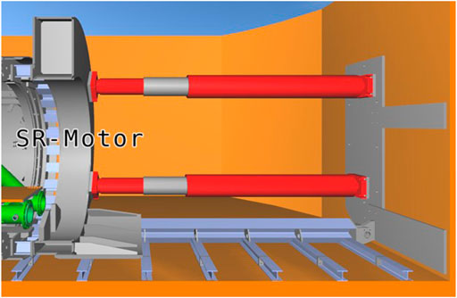
FIGURE 3. Propulsion cylinders in red.
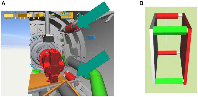
FIGURE 4. (A) Directional steering cylinders marked with arrows. (B) Visualization of the underlying physics simulation of the steering cylinders.

FIGURE 5. Simulation architecture of the virtual tunnel boring machine.
While the PLC is run on proprietary tools such as classical Siemens PLC and programmed in TIA, the virtual side of the simulator is developed and run in our in house open source virtual engineering system “PolyVR” (Haefner, 2014; Häfner, 2019). This open source 3D engine has been developed at our institute for research and industrial use cases mostly covering mechanical engineering but also interdisciplinary projects from other research areas such as building planning, chemistry, material science as well as education. We deploy this software environment to drive highly immersive visualization systems such as CAVEs or 3D Powerwalls and have extended in recent years to HMDs such as consumer-grade VR-glasses running through the SteamVR pipeline. While the source code of the engine, which holds all the connection modules for data exchange, communication protocols and interactive simulation cores is publicly available in C++ on GitHub (Häfner, 2014), the code of each single project is written mostly in Python with bindings to the functionality of PolyVR’s code base and usually not published.
3.5 Summary of contributions
Developing this simulation of the tunnel boring machine aimed at creating a driving simulator to train workers at monitoring and steering the tunnel boring process. The contributions of our work are:
• Developed a simulation system for a virtual tunnel boring machine, including the hydraulic subsystems and the water circuit.
• Developed an interface from the virtual tunnel boring machine to the original PLC code to obtain an authentic machine behavior.
• Developed a basic system to configure the simulated boring process.
• Developed a driving simulator to train driving a tunnel boring machine.
The development of this simulation has clearly shown the problems and challenges in creating virtual machine models. In the next section, methods to address these challenges will be presented in the context of another use case.
3.6 Methods for automated machine virtualization
The section above described the making of a virtual tunnel boring machine. This section will present methods of creating virtual machine models using algorithms, essentially trying to automate the virtualization process as much as possible. The use case here will be an integrated production line of chewing-gum. Virtual commissioning generally enables extensive validation of the planning data during product development, especially in special machine construction. However, the effort to create functional virtual models, to model the dynamics and kinematics, to parameterize the interaction with scripts and the real-time simulations is an enormous effort, for every machine model, version, variant and development progress. The automation of the creation of virtual functional and interactive machine models is a research field that has been addressed by the authors for several years (Häfner et al., 2020). They use it as a basis for all virtual engineering methods such as design reviews during product development, the virtual commissioning of production lines, training applications, maintenance simulations, material flow simulations and much more. Virtual engineering as a new working method in product development should make it much easier for engineers and product managers to validate the partial development or interfaces between the groups of engineers working on different parts of the product or machine. In addition, software and hardware in the loop methods and systems allow bringing work steps forward that can already start with the virtual components instead of real ones. Virtual commissioning allows validating models, including process and processing simulations. In order to consistently validate mechanical and electrical CAD as well as programming, automated virtualization systems must integrate all planning data into a virtual twin of the machine, system or integrated production line at the push of a button as depicted on Figure 6. For this purpose, generic intelligence is automatically added with the help of Semantic Web technologies and enables complex interactive models that can be used for training, monitoring and many other applications beyond the mere validation of planning data (Häfner, 2019; Häfner et al., 2020). Advanced applications that are based on virtual machine models are for example training and support applications, especially combined with augmented reality systems and remote collaboration systems, synchronous and asynchronous. In order to achieve this high degree of automation, geometry analysis algorithms were developed to capture as much intrinsic knowledge as possible in the mechanical CAD data and thus, for example, to automatically parameterize kinematic simulations. Such interactive simulation modules are important to simulate the behavior of the machines and processes and to give the user extensive interaction options. Another aspect is the automated aggregation of the entire knowledge from the planning data, in particular the merging of the component data in MCAD and ECAD. The software system used to implement the sub systems mentioned above, data interfaces, interactive simulations and virtual engineering applications is the virtual engineering system PolyVR (Haefner, 2014; Häfner, 2019).
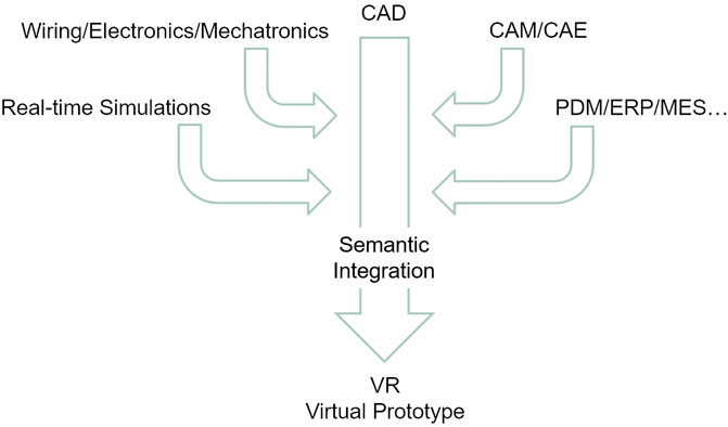
FIGURE 6. Integration of heterogeneous data sources towards the virtual prototype.
3.6.1 Mechanical simulation
For the simulation of a machine, the dynamic properties of the mechanical components are required. If the modeling of the mechanics and kinematics is not explicitly available in the MCAD data, this information must be determined elsewhere. For this purpose, after importing the mechanical design, geometry analysis algorithms are applied to the virtual model to calculate the parameters required for the simulation setup. The semantic layer contains the information which algorithms and parameters are required for the kinematic simulation of the different components. Figure 7 shows an example of the geometry analysis of a gear. First, a principal component analysis is used to determine the rotational axis of the gear. In the next step, by projecting the points of the geometry model into 2D polar coordinates and then fitting a sinusoidal function, tooth spacing and tooth height, among others, can be determined. Finally, the topology of the mechanical system is determined as shown in Figure 8. Then the simulation model is ready. The kinematic simulation determines the motion of mechanical components, considering the constraints imposed by collisions with other parts and mechanical connections. In addition, the user should be able to interact with the simulation. In PolyVR, mechanics can be simulated with interactive performance. In part, the classic physics engine Bullet (Coumans and Bai, 2016) is used, supplemented by an analytical simulation of mechanical constraints such as the interaction between gears, threads and chains. Here, movements of components are propagated through the mechanical chain. The most common combinations are gear-gear, gear-chain and gear-thread. Other links such as gear-axis and other kinematic joints attached to the mechanical parts are simulated by the physics engine. The way the simulation workflow is designed makes it very flexible. The simulation responds to any change in the model, especially user interaction. It may happen that the model undergoes changes on two mechanical elements that are mechanically inconsistent. This can be, for example, a collision or an incorrectly designed gearing. In this case, the mechanism locks. In the automated virtualization process, the mechanics simulation is automatically instantiated and parameterized. For this purpose, the relevant parameters are taken from the semantic layer (see Section 2.3). This contains, among other things, the mechanical properties of the components such as the gear pitch.
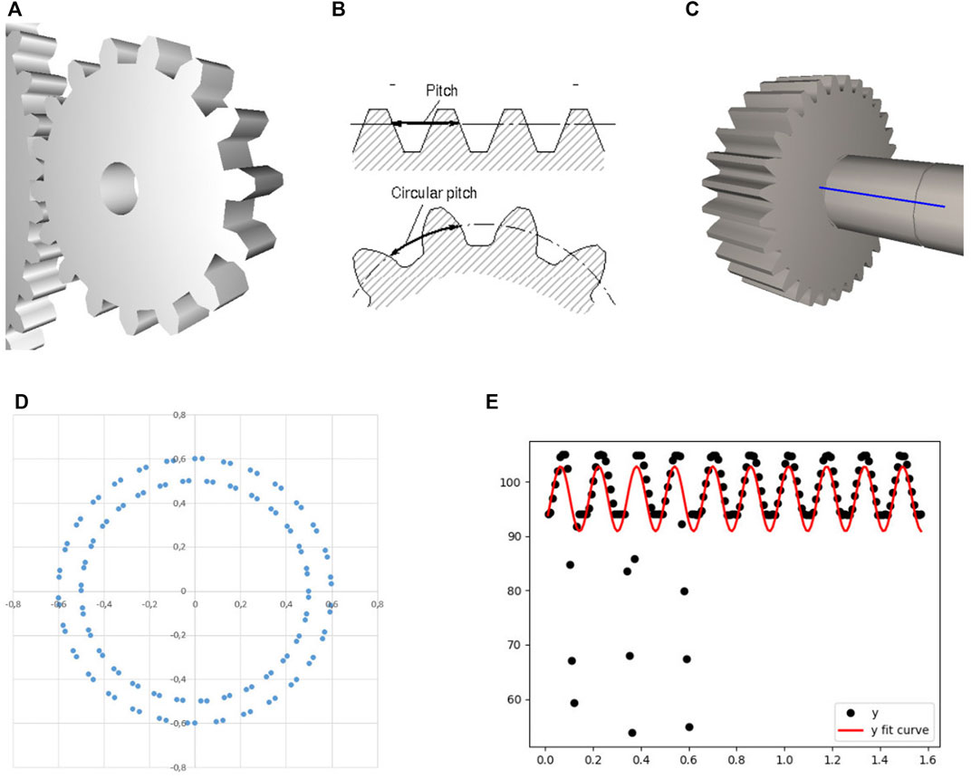
FIGURE 7. Process of geometry analysis to segment gear parameters like the pitch and teeth length.
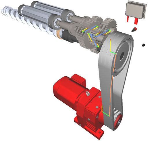
FIGURE 8. Kinematic chain, from the engine at the bottom to the gearing on top.
3.6.2 Electrical simulation
An important step in the virtualization process is the import of the ECAD data and its linkage with the MCAD models. The ECAD data and PLC programming are exported from the respective modeling tool. The data on which the implementation described here is based comes from EPLAN (EPLAN, 2022) and TIA Portal (Siemens, 2022b). The electrical CAD data, electrical components and wiring, are imported into PolyVR and inserted into the geometric mechanical model. Components are for example terminals, switches and PLC. Wiring consists of electrical cables and usually a bus system. Each electronic component has a unique ID and other metadata that is important for merging all data.
One challenge when importing ECAD data is that EPLAN does not provide a central project file with all the required data. The distributed data is imported to a data model of the power and communication network. One file contains a list of ECAD components and metadata. The next file contains the cabling as well as the cable designation, start addresses and destination addresses. An address is mostly structured according to the scheme
machine − component − socket: port
Where a component is identified with
machine − component
and
socket: port
is relevant for the simulation. Here in particular, the assignment of some ports to LAD variables is important. The difficulty now consists in the assignment of the electrical and the mechanical components to each other, at least for those components, which are present in both planning worlds. These are mostly actuators, sensors and HMI elements. Mapping takes place when there is sufficient correspondence between strings found in MCAD and ECAD data. Figure 9 shows the mechatronic components that are present in both ECAD and MCAD data and could be mapped automatically. The layout of the graph is automatically generated based on the 3D positions of the components. The visualization shows on which edges of the graph a current signal is present and updates itself when a change in the current network occurs due to the simulation described below.

FIGURE 9. Wiring graph and electrical components of the machine.
The mechatronic components and the power grid are simulated using graph traversal methods. A node is an electrical component and an edge is a cable. Starting from the main power supply node, the entire graph is traversed. The simulation essentially follows the electric current. The traversal starts with the main power supply node. Each evaluated node is marked to avoid duplicate evaluation. The components have multiple ports, the simulation determines how the current flows at the output ports depending on the component. The most basic component like a fuse simply allows current to pass. A more complex component is the switch, whose status defines whether the current can flow or not. The most complex components are the PLC modules, whose programming defines the current at the output ports. User interaction can change the state of the HMI components. For example, current flows to a PLC by pressing a switch. The port on the PLC sets a variable in the programming. The next section discusses emulation of PLC programming.
To bring the virtual plant to life, the behavior must be simulated, which is stored by the automation or the programming of the PLC. The programming defines how the PLC processes input signals and thus controls actuators, for example. The state of certain variables can be changed by analog or digital signals to the PLC from sensors or HMI components. Internal variables are changed by the program flow. Output variables define currents at the PLC output modules, these determine for example the behavior of the actuators. Machines often have touch panels that can be used to configure the behavior of the PLC and thus the machine. For example, actuators can be configured. The touch panels were virtualized in the 3D model as an interactive 2D surface. This is done with PolyVR’s website rendering module. The software and its user interface on the panel are replicated as a website. Machine-specific programming and configuration logic can be loaded generically and automatically. The panel displays the parameters that the user can change. This completes the functional chain of the virtual model so that the user can start and configure the virtual plant.
To simulate the behavior of the plant, the PLC program must be analyzed and its execution emulated. The programming language analyzed in this work is the Ladder logic language. The data used in the implementation of the LAD emulation is divided into different files, each containing the actual program logic, the variables with hardware addresses, the HMI programming and much more. This data must be combined to emulate the programming and interface with the wiring data model. The program is divided into what are called computational units, each containing a circuit diagram with operators and function blocks, as shown in Figure 10. The operators have inputs and outputs, and they are also connected to variables. When the operators are evaluated, the value of the variable determines the traversal.
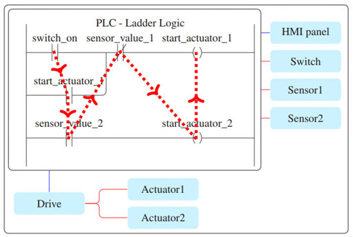
FIGURE 10. Example of ladder logic and the traversal of the operators.
The correct traversal of a computational unit is to prioritize the siblings, since nodes where two or more branches are merged must know the values of all previous nodes. The algorithm starts with the operator at the top left. The traversal is shown in Figure 10. The nodes, LAD operators and programming blocks, are evaluated in the process. When a variable is changed, the programming is traversed. This can happen, for example, after a user input or sensor activation. If the programming logic itself changes variables, the programming is run through as often as necessary until no more changes take place.
3.7 Evaluation parameters and results
We evaluated our results by assessing the system complexity for each component of the virtual machine model like the scene-graph, the semantic layer and each sub-simulation module. The machine model is the virtual production line described above. Next to the complexity we indicate the computation time per frame. The simulation ran on a gaming laptop with a GTX 1060, with a 31 s start-up time. The results are shown in Table 1.
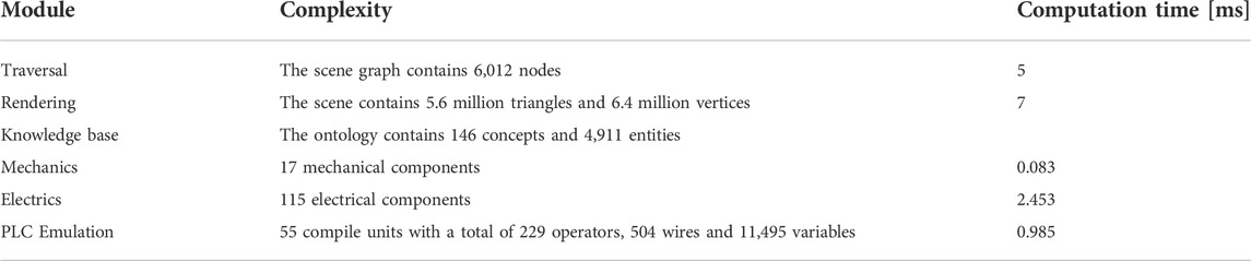
TABLE 1. Evaluation parameters and results.
The simulation is fast enough for real-time user interaction. There is also still enough buffer to simulate even larger machines as well as add more simulation modules like for example a material flow or a heat simulation.
3.8 Summary of contributions
With this work we were able to create a interactive virtual machine based on mechanical, electrical and programming CAD data using an automated workflow. The methodology was validated using a model of an integrated production line. Figure 11 shows the virtual plant. STEP data from SolidWorks, ECAD data from EPLAN and programming from TIA Portal were merged into a functional machine model. The contributions beyond the state-of-the-art are:
• Data interfaces and algorithms to merge MCAD and ECAD data into a common semantic data model.
• Geometry analysis algorithms to analyse and extract dynamic properties of gears and axles from CAD models.
• Automation of parameterizing simulation modules using a knowledge base.
• Automated integration of MCAD, ECAD, and PLC programming to simulate the authentic machine behavior.
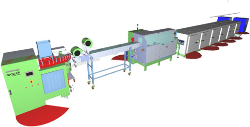
FIGURE 11. Integrated production line for chewing gum.
Next we list the impact our method has on the limitations of state-of-the-art systems to clearly present the scientific value of our work. The list of limitations has been presented in Section 2.1.
• Design review and virtual commissioning applications are turn-key ready fully automated systems, they will not require expert knowledge to be used productively. This should make it much more attractive for SMEs to invest in virtual engineering methods and systems.
• Not only static, but also dynamic and functional CAD validations are possible without an expert. This should greatly increase the added value generated.
• The virtualization of machines is now possible in a few minutes instead of days or weeks. This makes virtual engineering suitable to use during the product development as the virtual model will always be based on the most recent planning data.
This technology is the basis for a variety of VR applications in plant engineering. The automated virtualization is a fundamental game changer for design reviews with functional models up to virtual commissioning. But this method also greatly simplifies the authoring of more advanced applications that can use those functional machine models for software and hardware-in-the-loop, operation and maintenance training applications and virtual twins for configuring and monitoring. In this regard, the impact of optimizing the data interfaces, simulating as many aspects of machinery as possible and interactively, goes way beyond the product development process. For engineers, this offers a new horizon of possibilities, especially to create and deploy VR supported applications like training and monitoring in production settings and not only as demonstrators in academic settings. The next section will present methods to combine AI technologies with the virtual machine simulations.
3.9 Artificial intelligence and virtual environments
The simulation of machines, logistics and processes is complex as it is, especially when automating the creation of the simulation models from CAD planning data. But it is still rather classical development of data interfaces, data analysis, simulation algorithms and automating their parameterization. The next logical step in development is to infuse those fully dynamic and interactive virtual environments with intelligence. The following section will discuss the use of semantic web technologies, knowledge bases and reasoning engines, as well as causal inference in combination with machine learning (ML), to add more semantics and intelligent behavior to the virtual environments. We present multiple proof of concept use-cases.
An ontology in the context of the semantic web is a data structure that contains a taxonomy, a set of inference rules and a set of entities (Leo Kumar, 2019). The taxonomy contains concept labels with inheritance relationships that form a hierarchical structure. Each concept has a set of properties. The entities are data objects, instances of the concepts defined in the taxonomy, with a properties map of key-value pairs. Such an ontology allows to explicitly represent knowledge of the virtual environment. This in itself is very useful, for example for supporting complex application logic or enriching geometric models with semantic information. But the fascinating usage is combining the virtual environment with a reasoning system. Without going into the details of the internals of such an engine, it is important to understand its basic capabilities. A reasoning can answer questions based on the available knowledge. It does this using inference and other logic mechanics and analyze the entities and their properties of the virtual environment ontology.
Instead of training a system using labelled data, generic knowledge is explicitly given in a machine and human-readable form. This allows modeling complex knowledge, with many concepts bundled into domain specific taxonomies. An example of such an ontology that describes a virtual production is given in Figure 12, the resulting reasoning process is visualized in Figure 13. Those are of course only visualizations to explain the inner workings of the system, the author of the virtual environment needs of course to model the ontology for his application. This can be a lot of manual work to define the concepts, properties and create the entities, but using the automated virtualization process in combination with generic domain taxonomies can greatly reduce the amount of work in this regard. For the user who experiences the virtual environment, it should create a highly immersive experience where all elements in the environment behave consistently and intuitively. The goal is to use reasoning to deduce on run-time the reaction of the environment to the user interaction. This should greatly simplify the creation of highly interactive virtual worlds, especially having the ability to create new reactions based on logic to unexpected user interaction.
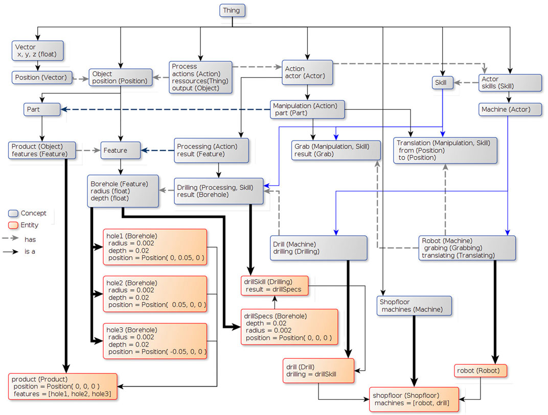
FIGURE 12. Semantic layer of a simple scene, gray boxes are the taxonomy concepts and the orange boxes the ontology entities.
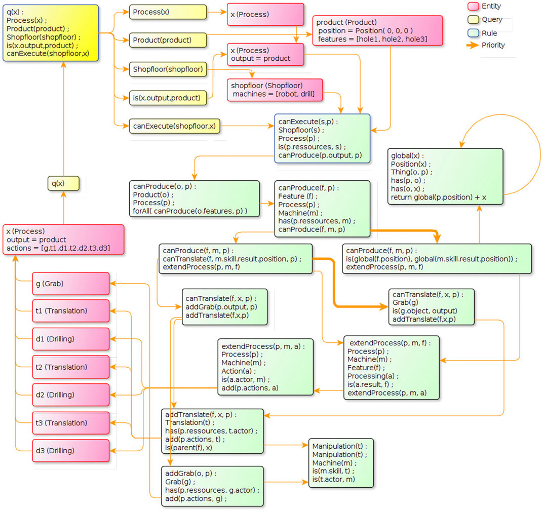
FIGURE 13. Fully unrolled processing of a query to the reasoning system.
3.10 Causal discovery in machine simulations
Another emerging technology of the artificial intelligence domain is Causal AI, in short it is about causal inference in combination with machine learning (Vuković and Thalmann, 2022). The idea is to be able to compute the effect of changing a variable on another variable using machine learning on time series. Based on this, it is possible to create causal graphs where the causal relations between variables are contained.
The automated virtualization is a complex system with many parameters and simulation sub-systems. There is thus a lot of intrinsic knowledge contained within the complex interaction between simulation modules when actually simulating the environment, for example a production line. The idea is to significantly expand the added value of such a functional model of an integrated production line by automatically converting intrinsic causal relationships in the model and the simulation into a graph structure using machine learning. The user should then be able to carry out complex analyzes in order to be able to optimize various aspects. This would be a perfect addition to a virtual engineering dashboard, where the user can introspect and interact with the virtualization system. One could easily explore the network of observables and their causal relations. An engineer could execute the most complex holistic analyzes of the planning data supported by the causal graph. Our concept to create such a causal discovery system is depicted on Figure 14.
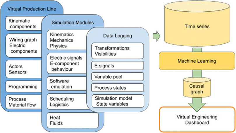
FIGURE 14. CausalVR concept, using CausalAI with simulations of interactive virtual models of machines and production lines.
A basic example of using causal AI methods with a machine simulation is based on the tunnel boring simulation described above. A core module of that simulation is the hydraulics simulation. This module has a simulation model that is completely embedded in the knowledge base. This greatly simplifies the process of creating a set of observables, the first step of applying causal analysis algorithms. The properties of all relevant entities like pipe segments, pumps, tanks and valves are the observables, they are logged during the simulation. Using machine learning techniques, the causal relations between those observables is computed. Figure 15 shows the first setup used to create the first time series. Two tanks are linked through a pipe with a pump in the middle and two valves around it. The three green buttons allow the user to toggle the valves and the pump. The blue dots and labels hovering above the 3D components are the observables deduced from the ontology model. After a short simulation run, a naive application of the Causal AI methods to the time series did indeed get promising results. The causality between opening the right valve and increasing pressure in the tank on the right was indeed discovered with a average treatment effect of 0.96 with lower and upper bounds of 0.94–0.99.
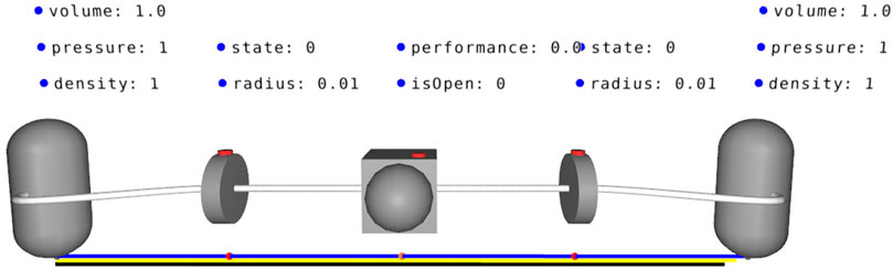
FIGURE 15. Simple hydraulics simulation to test causal discovery using machine learning.
4 Conclusion and outlook
The engineer of tomorrow will need to understand and manipulate much more complex systems and tools to manage the ever-growing requirements and complexity of product development. Those methods will not focus on easing modeling and planning like CAD systems, but much more on simulations and artificial intelligence to allow much faster development, much more advanced optimizations and much more efficient validation iterations. We proposed a system that combines virtual reality, virtual engineering and artificial intelligence methods for the product development process.
In the described use case of a TBM, we showed that generating a virtual simulation can easily reach a level of currently unwieldy complexity. While the general systems are simple to comprehend, most submodules require a platitude of parameters to mirror real life behavior to reduce the necessity for in depth numerical simulation models. We encountered many difficulties during the development of the simulation, and some do persist. A major issue is the communication over OPCUA which is very reliable but has major issues with bandwidth and latency. Different communication protocols such as MQTT might prove technically faster with less overhead. Another promising workaround would be, to connect directly onto the BUS system. While we currently cover most of the main features involved in the tunneling process, further supporting systems and submodules still need to be developed and included, such as the lubrication of the advancement through the deployment of bentonite to coat the TBM.
The TBM simulation was an important use-case to advance our software and hardware-in the-loop research. It will also help continue the research on automating the simulation parameterization. But most importantly it will be the perfect model, due to its semantic layer, for the causal AI research. In contrast to the TBM simulation, the production line simulation was created fully automatically. There the focus lies on the product development process and the toolset for engineers during that process for validating their planning data. There, the integration of causal AI methods is very promising to greatly increase the added value of virtual engineering methods. Our vision is to be able to select a specific parameter of the machine or production line to be optimised. Then the system displays all the nodes from the causal graph that directly impacts the selected parameter. Those are the adjusting screws that can be used for the optimization. But it does not halt there, the user can check each node to see its causal ramifications throughout the whole simulation and decide, based on the causal effects of each node, which one to actually change. Such a tool would be a real game changer for virtual engineering as a whole. Further integration of AI methods such as causal inference into our software and hardware-in-the-loop approaches within the virtual simulation system will improve the overall maturity and efficacy of how its application can be employed in the product life cycle.
Further research and efforts to bring advanced causal inference algorithms into virtual engineering applications will be pursued, as will the topic of interactive reasoning to create true generic smart virtual environments. The combination of knowledge based inference engines with machine learning based causal discovery is very promising. A next step in that direction is to build a system that automate the process of creating that causal graph. Further, explore the state-of-the-art causal AI algorithms and methods and how to apply them to engineering use cases. Especially regarding time series, there are methods like Granger and Toda-Yamamoto causality (Moraffah et al., 2021) that may help handle the causal effects delayed in time. It is also necessary to better scale performance wise with big models and long time series, as part of the algorithms should be applicable in real-time.
Data availability statement
The original contributions presented in the study are included in the article/Supplementary Material, further inquiries can be directed to the corresponding author.
Author contributions
This article was written by FM and VH. FM mainly worked on the texts regarding the tunnel boring machine use-case throughout all sections. VH worked on the topics of automation of the virtualization process and artificial intelligence. Both authors agree to be accountable for the content of this work.
Funding
The work presented in this paper was mostly funded by the Karlsruhe Institute of Technology. We acknowledge support by the KIT-Publication Fund of the Karlsruhe Institute of Technology. Some aspects were researched in the scope of various research, industry and student projects. The funding for the virtual tunnel boring simulation came partly from the company Herrenknecht AG in Germany.
Acknowledgments
For the possibility to further pursue our research at IMI-KIT, and work on innovative projects, we thank our institute head -Ing. h c. Jivka Ovtcharova. We thank Herrenknecht AG for the opportunity to develop and improve our research regarding virtual twins, the methods for SiL, HiL and letting us extend our path of sensible application of AI in engineering. Especially impactful were the colleagues M. Bischoff and S. Uhl. We are thankful for the engineering data provided by Gabler Engineering GmbH to develop the automation process for creating virtual twins through integration of mechanical, electrical and semantic information.
Conflict of interest
The authors declare that the research was conducted in the absence of any commercial or financial relationships that could be construed as a potential conflict of interest.
Publisher’s note
All claims expressed in this article are solely those of the authors and do not necessarily represent those of their affiliated organizations, or those of the publisher, the editors and the reviewers. Any product that may be evaluated in this article, or claim that may be made by its manufacturer, is not guaranteed or endorsed by the publisher.
References
Bayart, B., Vartanian, A., Haefner, P., and Ovtcharova, J. (2015). Techviz xl helps kits formula student car “become alive”. IEEE Virtual Real. (VR), 395–396. doi:10.1109/VR.2015.7223462
Bönsch, J., Elstermann, M., Kimmig, A., and Ovtcharova, J. (2022). A subject-oriented reference model for digital twins. Comput. Industrial Eng. 172, 108556. doi:10.1016/j.cie.2022.108556
Chang, M., Ko, M., and Park, S. C. (2011). Fixture modelling for an automotive assembly line. Int. J. Prod. Res. 49, 4593–4604. doi:10.1080/00207543.2010.506893
Chen, H., Harinen, T., Lee, J.-Y., Yung, M., and Zhao, Z. (2020). Causalml: Python package for causal machine learning. arXiv, 11631.
Coumans, E., and Bai, Y. (2016). Pybullet, a python module for physics simulation for games, robotics and machine learning. Available: http://pybullet.org.
AutomationML (2022). Automationml description. Available at: https://www.automationml.org/. (Accessed 2022-08-30).
EPLAN (2022). Eplan description. Available at: https://www.eplan-software.com/. (Accessed 2022-08-30).
Haefner, V. (2014). “PolyVR - a virtual reality authoring system,” in EuroVR 2014 - conference and exhibition of the European association of virtual and augmented reality, Bremen, Germany. Editors J. Perret, V. Basso, F. Ferrise, K. Helin, V. Lepetit, J. Ritchieet al. (Geneva, Switzerland: The Eurographics Association). doi:10.2312/eurovr.20141343
Häfner, V., Benedix, A.-C., and Häfner, P. (2020). Automatisierung des virtualisierungsprozesses im anlagenbau. Z. für Wirtsch. Fabr. 115, 148–152. doi:10.3139/104.112253
Häfner, V. (2014). Polyvr source. Available at: https://github.com/Victor-Haefner/polyvr. (Accessed: 2022-08-31).
Häfner, V. (2019). “PolyVR-a virtual reality authoring framework for engineering applications,” (Karlsruhe: Karlsruher Institut für Technologie KIT). Ph.D. thesis, Dissertation.
Hauf, D., Kruck, J., and Franke, J. (2017). Energy consumption modeling of a turning table and standardized integration into virtual commissioning. Procedia Manuf. 11, 256–264. doi:10.1016/j.promfg.2017.07.359
Jun, C., Yadong, G., and Jianyu, Y. (2009). “Research of simulation for tunnel boring machine based on virtual reality,” in Proceeding of the International Conference on New Trends in Information and Service Science, Beijing, China (IEEE), 1038–1041.
Ko, M., Park, S. C., Choi, J.-J., and Chang, M. (2013). New modelling formalism for control programs of flexible manufacturing systems. Int. J. Prod. Res. 51, 1668–1679. doi:10.1080/00207543.2012.693964
Leo Kumar, S. (2019). Knowledge-based expert system in manufacturing planning: State-of-the-art review. Int. J. Prod. Res. 57, 4766–4790. doi:10.1080/00207543.2018.1424372
Li, G., Cao, Y., Yao, Y., and Wang, W. S. (2010). A desktop virtual reality-based interactive tunnel boring machine simulation system. Adv. Mat. Res. 139, 957–960. doi:10.4028/www.scientific.net/amr.139-141.957
Li, H., and Du, E. (2016). Simulation of rock fragmentation induced by a tunnel boring machine disk cutter. Adv. Mech. Eng. 8, 168781401665155. doi:10.1177/1687814016651557
Mao, S., Shen, X., Lu, M., and Wu, X. (2013). “Real-time tablet-based virtual reality implementation to facilitate tunnel boring machine steering control in tunnel construction,” in Proceedings of the 13th International Conference on Construction Applications of Virtual Reality (CONVR2013), London, United Kingdom.
Moraffah, R., Sheth, P., Karami, M., Bhattacharya, A., Wang, Q., Tahir, A., et al. (2021). Causal inference for time series analysis: Problems, methods and evaluation. Knowl. Inf. Syst. 63, 3041–3085. doi:10.1007/s10115-021-01621-0
Ninić, J., and Meschke, G. (2015). Model update and real-time steering of tunnel boring machines using simulation-based meta models. Tunn. Undergr. Space Technol. 45, 138–152. doi:10.1016/j.tust.2014.09.013
Park, H.-T., Kwak, J.-G., Wang, G.-N., and Park, S. C. (2010). Plant model generation for plc simulation. Int. J. Prod. Res. 48, 1517–1529. doi:10.1080/00207540802577961
Reinhardt, H., Weber, M., and Putz, M. (2019). A survey on automatic model generation for material flow simulation in discrete manufacturing. Procedia CIRP 81, 121–126. doi:10.1016/j.procir.2019.03.022
Schroeder, G. N., Steinmetz, C., Pereira, C. E., and Espindola, D. B. (2016). Digital twin data modeling with automationml and a communication methodology for data exchange. IFAC-PapersOnLine 49, 12–17. doi:10.1016/j.ifacol.2016.11.115
Sepasgozar, S. M. (2020). Digital twin and web-based virtual gaming technologies for online education: A case of construction management and engineering. Appl. Sci. 10, 4678. doi:10.3390/app10134678
Siemens (2022a). Siemens simit description. Available at: https://new.siemens.com/de/de/produkte/automatisierung/industrie-software/simit.html. (Accessed 2022-08-30).
Siemens (2022b). Tia portal description. Available at: https://new.siemens.com/global/en/products/automation/industry-software/automation-software/tia-portal/software.html. (Accessed 2022-08-30).
Thongnuch, S., and Fay, A. (2017). “A practical simulation model generation for virtual commissioning,” in Proceeding of the IEEE International Conference on Advanced Intelligent Mechatronics (AIM), Munich, Germany (IEEE), 1077–1082. doi:10.1109/AIM.2017.8014162
Vuković, M., and Thalmann, S. (2022). Causal discovery in manufacturing: A structured literature review. J. Manuf. Mater. Process. 6, 10. doi:10.3390/jmmp6010010
Wolfartsberger, J. (2019). Analyzing the potential of virtual reality for engineering design review. Automation Constr. 104, 27–37. doi:10.1016/j.autcon.2019.03.018
Wu, H., Zhu, Q., Guo, Y., Zheng, W., Zhang, L., Wang, Q., et al. (2022). Multi-level voxel representations for digital twin models of tunnel geological environment. Int. J. Appl. Earth Observation Geoinformation 112, 102887. doi:10.1016/j.jag.2022.102887
Keywords: virtual reality, virtual engineering, causal AI, tunnel boring machine, virtual twin, virtualization process, hardware in the loop, software in the Loop
Citation: Michels FL and Häfner V (2022) Automating virtualization of machinery for enabling efficient virtual engineering methods. Front. Virtual Real. 3:1034431. doi: 10.3389/frvir.2022.1034431
Received: 01 September 2022; Accepted: 31 October 2022;
Published: 23 November 2022.
Edited by:
Esteban Clua, Fluminense Federal University, BrazilReviewed by:
Francesco De Pace, Polytechnic University of Turin, ItalyRadu Petruse, Lucian Blaga University of Sibiu, Romania
Copyright © 2022 Michels and Häfner. This is an open-access article distributed under the terms of the Creative Commons Attribution License (CC BY). The use, distribution or reproduction in other forums is permitted, provided the original author(s) and the copyright owner(s) are credited and that the original publication in this journal is cited, in accordance with accepted academic practice. No use, distribution or reproduction is permitted which does not comply with these terms.
*Correspondence: Victor Häfner, dmljdG9yLmhhZWZuZXJAa2l0LmVkdQ==