 Nawel Khenak
 Jeanne Vézien
 Patrick Bourdot
- CNRS, LIMSI, VENISE Team, Université Paris-Saclay, Orsay, France
Although many augmented reality (AR)-based assembly support systems have been proposed in academic research and industry, the effectiveness of AR to resolve the occlusion issue in the context of a blind assembly process remains an unexplored topic. Therefore, the present work investigates how AR can assist operators during the execution of blind manual assembly tasks. Specifically, an AR research set-up was designed to provide assistance in occlusion situations during a peg-in-hole task. The set-up featured a see-through device (HoloLens), which provides operators with two modes of visual augmentations that directly overlay on the assembly objects. The first mode referred to as the “wireframe overlay” displays the inner part of the objects, providing an inside view of the occluded parts, and the second one referred to as the “axes overlay,” displays the axes of the objects and their slots, indicating how to align the different parts during the assembly. The effectiveness of these AR visualizations was compared to a baseline augmentation-free situation in a controlled experiment. Thus, following a within-subject design, 30 participants performed a two-stages blind insertion task. Their performances represented by task completion time, insertion errors, and smoothness of the insertions were recorded. In addition, a post-questionnaire reported their subjective perception of task difficulty during the task and their preferences. Results indicated a strong acceptance of participants for AR visualizations that they rated as allowing them to perform the task more easily. However, no statistically significant differences in terms of objective performance measures were found. Yet, it was found that axes overlay produced smoother trajectories compared to the wireframe overlay, highlighting the potential effect of more abstract visualization aids.
Introduction
Manual assembly tasks represent one of the most extensively studied manual processes in manufacturing where “automation is not cost-effective, products are highly customized, or processes cannot be done by automatic machines” (Tang et al., 2003). One of the main challenges of these studies is to enhance the assembly information that guides a human operator when performing the assembly process. Assembly information, such as textual instructions, drawings or schematics, in the form of paper or electronic manuals, is often separated from the assembly product. Therefore, the operator would usually need to switch his/her attention between the assembly instructions and the parts being assembled. These switches of attention may lead to reduce productivity, increase assembly times and errors, as well as strain injuries (Khuong et al., 2014). By replacing these types of information and providing adequate guidance to the operator during the manual assembly task, one could reduce operation time and cost, and improve the quality of manufacturing processes.
Thus, to assist operators during such tasks, different approaches were proposed. Among them, the use of haptic technology to provide more realistic feedback during the assembly process, such as feeling the weight of the parts to be assembled or the contact force when objects collide (Seth et al., 2006). Other researches also suggested the use of haptics to define virtual constraint guidance—for example when wearing gloves (Valentini, 2009), or using vibrotactile feedback (Arbeláez et al., 2019)-, which helps operators to find the right alignment on the assembly constraint (Tching et al., 2010; Wildenbeest et al., 2012).
While haptic technology for manual assembly tasks showed certain benefits, there are still many limitations that prevent its wide-spreading. Indeed, to maintain stability in real-time, haptic simulations are required to calculate forces at a high frame-rate (1 kHz), which makes their use computationally expensive. Moreover, they generally operate with intrusive mechanical structures or equipment (instrumented gloves, exoskeletons, and robotic arms) that disturb operators during the task or restrict their gesture, which in turn affects the performance (Bashir et al., 2004). For a more detailed review of assembly with haptic feedbacks and its limitations, see Perret et al. (2013).
In parallel to the use of haptic technology, an increasingly common approach is the use of Augmented Reality (AR) to provide visual cues that help operators during the assembly process (Unger et al., 2002; Petzold et al., 2004; Funk et al., 2016a). AR is a human-machine interaction tool that overlays computer-generated information (e.g., 3D models and annotations) on the real-world environment perceived by a human user (Azuma, 1997; Azuma et al., 2001). AR makes it possible to display digital assembly information in the operators' field of view according to the situation (i.e., depending on the observed objects). Hence, it can improve assembly operations through essential step-by-step real-time instructions. The operators can concentrate on the tasks at hand without having to change their head or body positions to access the next instruction. Consequently, AR technology could provide an efficient and complementary tool to assist assembly tasks.
Many researchers in the manufacturing industries (Caudell and Mizell, 1992, Curtis et al., 1999), as well as in academic institutes and universities (Doil et al., 2003; Reinhart and Patron, 2003) have explored the use of AR technology in assembly activities. As a result, several prototype applications were introduced, which show the benefits of using AR assistance in manual assembly operations (Reiners et al., 1999; Zenati et al., 2004; Regenbrecht et al., 2005). See Nee et al. (2012) and Ong et al. (2008) for an overview of AR applications in manufacturing. Thus, in comparison with conventional guidance methods, such as paper-based work instructions, assembly guidance systems based on AR can help reduce search time for relevant instructions as well as reduce the mistakes (Tang et al., 2003; Henderson and Feiner, 2011; Hou and Wang, 2013; Korn et al., 2013; Zhu et al., 2013). In addition, it allows the user to focus on the task by displaying guidance materials close to the working area spatially to minimize attention switching (Khuong et al., 2014), thus reducing the mental workload (Robertson et al., 2008; Hou and Wang, 2013). Finally, it improves user acceptance (Nilsson and Johansson, 2007; Webel et al., 2013).
However, although the use of AR to support assembly tasks has been a focus of interest over the last decade, few researchers and industrials have addressed the problem of occlusion that can occur during “blind” manual assembly task, i.e., when the view of the operator can be blocked, partially or totally, by the elements to be assembled.
The purpose of the present paper is to evaluate the effectiveness of an AR-based assembly prototype consisting of two types of AR visualizations in order to understand how best to assist operators in the context of manual blind assembly tasks.
The remainder of this paper is divided into six sections. The second section provides an overview of related works highlighting the research focus and the main objective of the present study. The third section presents the AR system designed to address the visual occlusion issues that occur during blind assembly tasks. The user evaluation procedure is reported in the fourth section. It is followed by statistical analysis and subsequent results in the fifth section. In the sixth section, these results are discussed. The seventh and last section concludes with some future work directions inspired by the present findings.
Rationale and Motivation
AR assistance for manufacturing and assembly domain activities is about as old as augmented reality itself, with the first AR-based assembly system introduced, in 1992, by engineers at Boeing to aid workers in the assembling of wires on a mounting plate, through displaying pertinent instructions and diagrams on a head-mounted display (HMD) (Caudell and Mizell, 1992; Sims, 1994; Curtis et al., 1999). Although they could demonstrate the feasibility of their system, they encountered several usability issues due to hardware and software limitations.
Since then, many experiments have been conducted to investigate the effectiveness of AR assistance for manual assembly tasks. Baird and Barfield (1999) conducted an experiment when operators had to assemble computer motherboards using four types of instruction media (paper, model on display, video-see-through and optical-see-through HMD). Results indicated that AR-based assembly guidance was more effective than other forms of instruction: operators achieved the assembly in a shorter amount of time while making fewer errors. Tang et al. (2003) compared the effectiveness of AR instructions for assembling Duplo blocks against three other types of instructional media [a paper-based instruction set, computer-assisted instruction (CAI) using a monitor-based display, and CAI utilizing HMD]. Results showed that that overlaying 3D AR instructions on the actual pieces reduced the error rate for an assembly task by 82% compared to more conventional instruction sets. In the same year, several AR-based assembly guidance systems where developed (Reinhart and Patron, 2003; Zauner et al., 2003; Yuan et al., 2004). Nakanishi et al. (2007) evaluated the use of an AR manual in a wiring task. They found that the wiring time was shortened by about 15% and at the same time, the error in wiring positions was reduced to almost zero. For a detailed survey of AR-based assembly applications between 1990 and 2015, see Wang et al. (2016).
The majority of the AR research appears to have originated from academia. Industrial AR applications are far less reported in comparison. Yet, AR-based assembly guidance in industries is a strong and growing area. Several industrial projects demonstrated prototypes that allow computer-guided assembly of complex mechanical elements using augmented reality techniques, showing the benefits of AR technology for assembly tasks (Schwald et al., 2001; Hillers et al., 2004; ARVIKA1; ARTESAS2) In fact, the more complex the product is, the greater the potential benefit from the use of AR technology can be. Consequently, many manufacturing companies are integrating AR technology into their assembly activities. For a detailed review of industrial AR applications in manufacturing, see (Nee et al., 2012).
With the advent of technological developments in augmented reality systems (Zhou et al., 2008), mainly in tracking techniques and especially the vision-based tracking techniques (Sivaraman and Trivedi, 2013), and display devices (Ardito et al., 2015) such as projection-based displays and head-mounted displays, smaller, sophisticated, and even wearable AR-based manual assembly systems were designed and several academic studies, as well as industrial projects, have been conducted to evaluate their effectiveness.
Thus, recent attempts to investigate AR visual assembly guidance have been proposed. Based on the work of Tang et al. (2003) and Funk et al. (2015) proposed Duplo blocks assembly tasks as a standardized lab-style experiment design to evaluate AR instructions. They followed this design to compare HMD instructions, tablet instructions, and baseline paper instructions to in-situ AR projected instructions. They found that participants were faster and made fewer errors using AR projected-based instructions compared to HMD instructions (Funk et al., 2016b). Following this trend, Blattgerste et al. (2017) compared in-situ instructions to conventional in-view instructions using a smartphone, Microsoft HoloLens, Epson Moverio BT-200 smart glasses, and paper-based instructions. Like their predecessors, the in-situ instructions consisted in displaying at each step a cuboid with size and color that corresponds to the Lego Duplo brick that had to be assembled at the correct assembly position. The results showed that the participants were faster using the paper instructions but made fewer errors with in-situ instructions using the Microsoft HoloLens. Nishihara and Okamoto (2015) and Okamoto and Nishihara (2016) proposed an AR system for guiding the assembly of a Pentomino puzzle. The system consisted of a fixed tablet computer between the participant and the parts, on which visual indications of final positions were displayed. Similarly, puzzles have been largely used in AR for testing assembly implementations (Kitagawa and Yamamoto, 2011; Syberfeldt et al., 2015).
In parallel, Radkowski et al. (2015) analyzed the dependency between two factors that may affect the effectiveness of AR assembly guidance systems, namely, the complexity of the manual assembly task (assembly of an axial piston motor in this case) and the complexity of visual features used to present the assembly steps. The features were adapted to the level of difficulty and varied from textual information on the screen describing the task, 2D sketches, and static 3D virtual models, to 3D arrows used to indicate the assembly location or the assembly path, as well as 3D animations to show the assembly method. They found out that the visual features must correspond to the relative difficulty level and that the difficulty of the task does not affect the user's assembly performance (i.e., the assembly time). Their results also showed that the visual features for AR assistance increase the user's confidence despite the fact that they did not find statistically significant results regarding assembly time. Syberfeldt et al. (2015) followed the same idea except that they used AR overlaying information on the real objects to identify the correct object to be assembled. Their work was based on results from Pathomaree and Charoenseang (2005) and Seok and Kim (2008), which indicated that simpler visual features can be used when 3D models overwhelm the user. They developed an AR prototype based on the Oculus Rift platform and evaluated it through the assembling of a 3D puzzle, in order to investigate user acceptance. The results showed that the most important keys improving acceptability were that the complexity of the assembling task must be significant and that the AR system should make the user more efficient. Horejší (2015), on the other hand, proposed to use a monitor placed in front of the user that displayed the final image with virtual 3D models. He focused on displaying the order of the tasks to be performed and measured time improvement in assembly tasks in comparison with the classic method. More recently, Ojer et al. (2020) presented a new projection-based AR system for assisting operators during electronic component assembly processes. The proposed system consists of four different parts: an illumination system, a 2D high-resolution image acquisition setup, a screen and a projector located at sufficient height in order to not disturb the operator during manual operation. The main goal of this tool was to generate models able to highlight the missing electronic components on the board. Results of a study they conducted showed that operators actually find the system more usable, feel more secure with it, and require less time to perform their tasks.
Therefore, AR-based assembly guidance has demonstrated its effectiveness compared with classic assistance methods (digital and paper manuals) such as time and error rate reduction and increased user acceptance. Displaying directly the information to the user, it is possible to avoid the attention swapping, the execution of repetitive movements and, at the same time, simplifying user's decisions (Tang et al., 2003; Yuan et al., 2008; Henderson and Feiner, 2011; Arbeláez et al., 2019).
While these researches provided strong evidence for the value of AR, they mainly focused on two ways to provide visual aids, namely by:
• Displaying 2D information—such as textual information, numerical values or 2D sketches—that is relevant to what is under observation e.g., the description of the current operation (Radkowski et al., 2015) or the order of the operations the user needs to follow to perform the task (Horejší, 2015);
• Displaying 3D virtual objects inserted within the real environment in spatially registered positions that can represent either 3D indications such as arrows to show the correct location or the pose of the real object. Consequently, the user is instructed on how to assemble real components together (Syberfeldt et al., 2015; Funk et al., 2016b; Blattgerste et al., 2017).
These visual features are added to the real components of the assembly task. They represent external information that does not exist outside the framework of the experiment. As a result, they can lead to an overload of the real scene and therefore increase the mental workload (Hou and Wang, 2013; Markov-Vetter and Staadt, 2013). Moreover, although much effort has been expended on this topic, there are still many unsolved issues such as the visual occlusion issue that happens during blind assembly tasks when objects or parts of objects are occluded.
In contrast to these prior works, the focus is given in this paper on integrating extra geometric information to the objects to be assembled. To be useful for blind assembly, the information should represent some important, intrinsic properties of the objects that are not directly visible to the users. The information can be implicit, such as symmetries, axis, etc., or explicit, i.e., portions of objects that are occluded during the assembly. By visualizing hidden information with AR, one could perform blind assembly tasks that would otherwise be difficult or even impossible to accomplish.
Therefore, the aim of this work is to develop an augmented reality (AR) system helping users when performing blind assembly tasks, by providing them with AR visualizations appropriate to this issue. To achieve this purpose, two different modes of AR visualizations are proposed:
(1) Highlight the hidden part of the objects (i.e., the inner and/or the rear part) as well as the parts occluded by other objects; information is selected solely on the basis of visibility criteria.
(2) Display only the axes of the objects (or similar structural features) so that their relative positions become explicit. This time, information is selected based on its relevance with respect to the insertion task.
Then, an evaluation is conducted to explore the potential benefit of these AR visualizations methods to assist users in blind assembly situations compared to a baseline situation where no AR is provided.
Experimental Design
In order to provide AR visualizations as support for blind tasks, an AR-based assembly prototype system was designed consisting of 3D visual overlays displayed on a head-mounted device and a controlled blind insertion task designed as follows.
Blind Insertion Task
It was not possible to rely on previous works consisting in standardized assembly set-ups that are mainly designed for “pick-and-place” tasks, and where the occlusion issue is not addressed (Tang et al., 2003; Funk et al., 2015; Blattgerste et al., 2017). Instead, a blind assembly process was designed based on the “peg-in-hole” manipulation, where an object must be inserted in another without direct visibility on the insertion area (Chhatpar and Branicky, 2001; Park et al., 2013; Abdullah et al., 2015; Zhang et al., 2017). Insertions are an important aspect of assembly: tight tolerances between objects involved in the insertion, as well as positioning accuracies, require some level of compliance, and trajectory control (Lim et al., 2007). Insertion tasks are also found in a wide variety of maintenance and automotive applications, making them suitable standardized tasks that should be studied.
Therefore, three objects to be assembled were designed and manufactured3:
- a box with three –not aligned- slots on the top side and one slot on the slide,
- a board with three slots on its middle area,
- a second board with no slots.
The objects were built in medium-density fiberboard, a material light enough for easy handling, yet strong enough to guarantee some durability throughout the experiment. In addition, visual targets were engraved on the object for tracking purposes (see section Tracking Set-Up), once again ensuring pattern durability over time. Informal interviews after the experiment did not reveal any visual confusion due to the targets printed on the objects.
Using these three objects, a two-operation insertion routine was carried out in the following order:
Operation 1: Insert the first board (the one with slots) through the box laterally from left to right.
Operation 2: Insert the second board into one of the three vertical slots on the top of the box, then through the previously inserted board (choosing the correct slot that allows for a vertical insertion).
Refer to Figure 1 for a graphical description of the assembly task.
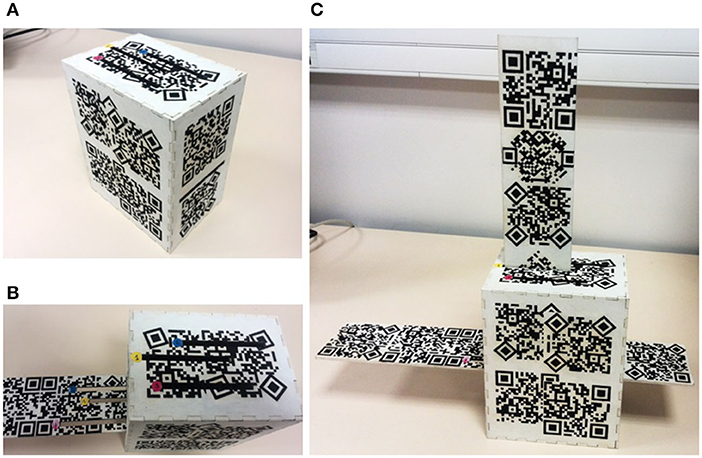
Figure 1. The assembly set-up at different stage of the insertion task. (A) The box before the insertion. (B) The first board during the insertion into the box (operation 1). (C) The second board inserted into the box and the first board (operation 2).
Visual Overlays
As mentioned above, previous works have focused on procedural augmentation, such as 2D or 3D instructions. In this study, the focus was given instead on the later stage of actual assembly and more precisely how geometric overlays can compensate human senses during critical phases, such as insertions. Thus, two 3D visual overlays -associated with the assembly objects- were designed: the “wireframe” overlay and the “axes” overlay (see Figure 2). They are described in the following.
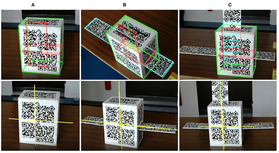
Figure 2. The First-Person View (FPV) on the HoloLens (captured from the Mixed Reality Viewer) displaying both AR overlays (per line), at the different stages of the task (per column). First line, the wireframe overlay, second line, the axes overlays. (A) Before starting the task. (B) After operation 1. (C) After operation 2.
Wireframe Overlay
The wireframe overlay employs wire-frame models of the assembly objects to display an X-ray vision of the assembly parts. AR X-ray vision has been used in different fields (Bane and Hollerer, 2004; Avery et al., 2007, 2009). In particular, it was used in medical scenarios to provide a 3D view of the regions to be operated in real-time, so that surgeons can intervene in an easier and more accurate manner (Bajura et al., 1992; Navab et al., 2009; Zang et al., 2009; Tabrizi and Mahvash, 2015).
Based on the analogy that exists between the regions to be operated and the objects to be assembled, the wireframe overlay was proposed to improve the perception of relative placement of the objects in an assembly and provide additional depth cues, by virtually representing visible and invisible contours. In other words, this overlay will display all the outlines and inner parts of objects during the assembly. This would allow operators to get an inside view of the occluded parts.
Axes Overlay
As previously mentioned in Valentini (2009), Tching et al. (2010), and Wildenbeest et al. (2012), performance can be improved in an assembly task by defining virtual constraints on the objects using haptic devices. It could, therefore, be interesting to reproduce such constraints using only visual guidance in order to encourage operators to follow a certain path while inserting the objects. Thus, in the axes overlay, the axes of the objects and their insertion features (slots) are displayed to indicate to operators how to align the different objects during the assembly.
Apparatus
Device Set-Up
A commonly available AR viewing device is the see-through head-mounted display (HMD). For such a device to be operated in assembly operations, it must be lightweight and small enough not to obstruct the user's view, and computationally powerful enough to be able to interpret specific user input and the environment (Azuma et al., 2001). The user should also be able to interact with the devices in a most natural way, without awkward postures and gestures (Carmigniani et al., 2011).
For these reasons, the decision was made to use a Microsoft HoloLens running a 32-bit version of the Windows 10 operating system, with an Intel Atom x5-z8100 processor consisting of four 64-bit cores running at 1.04 GHz. In addition, it features an HPU/GPU Holographic Processing Unit, 64 GB Flash, 2 GB RAM, and 2–3 h of active battery life that allows the standalone operation of this device (Furlan, 2016). Moreover, it is a completely self-contained HMD, i.e., it does not require the HMD to be tethered to a separate computing device.
Tracking Set-Up
The one area in which the HoloLens falls short is tracking the location of the parts and assembly station. Such an intricate assembly requires precise location capabilities and a high level of accuracy in tracking and superimposition of augmented information (Nee et al., 2012). The HoloLens does have spatial mapping capabilities; however, the mesh created is not accurate enough for a detailed assembly application. Microsoft does currently suggest that if a developer wants to use marker-based tracking, the Vuforia plug-in for Unity3D should be used4 All implementation details on how to configure a Vuforia app for Hololens can be found on their website5.
Therefore, the HoloLens built-in tracking system was replaced by a more accurate tracking procedure based on a marker-based approach, implemented using the Vuforia 6 SDK. Consequently, each object to be tracked was covered with visual targets that would be recognized by the Vuforia API on the HoloLens. Special care was taken to preserve high local contrasts and avoid repetitive patterns to obtain satisfactory tracking performances. Refer to Vuforia's website6 for a better understanding of the tracking requirements. Given these precautions, the HoloLens could properly track object positions as the user moves them around in the assembly area. That is crucial because, without the specific location of each component being tracked, the device cannot achieve true AR capabilities.
This approach has allowed to provide an easily reproducible and ecologically valid system without any external tracking apparatus and design a completely portable, lightweight, and easy to handle set-up. In particular, the portable AR gear was comfortable to wear while providing satisfactory AR assistance.
Finally, the 3D models of the assembly objects were created on Blender 2.6, then imported in Unity3D 5.5.2 where custom Vuforia targets were generated. The AR rendering overlays were implemented in C# using custom shaders in Unity3D.
Factors
A within-subjects design experiment was run with two fixed variables:
[VISUAL] The visual overlay with three modalities labeled WIR, AXE, and BAS representing, respectively, both wireframe and axes visual overlays, and a baseline condition with no AR visualization provided to allow a comparison of the AR conditions with the natural operator condition during the assembly.
[SLOT] The numbered slot (located on the top of the box and the first board) in which the participants had to insert the second board. There were three modalities representing the three slots numbered from 1 to 3. This variable was considered as a repeated measure in the evaluation.
The order of both variables was counterbalanced across participants using Latin Square for [VISUAL] and randomization in an equal way for [SLOT] in order to reduce the order effect and avoid bias the results.
User Evaluation
Participants
Thirty participants took part in the experiment (21 males, 9 females) with ages ranging from 19 to 59 years old (mean = 29, SD = 10). They reported an average degree of expertise with HMDs of 1.83 on a 5 point Likert scale (1 meaning no experience and 5 meaning very experienced). The only condition to participate was to have a normal or corrected to normal vision (the HoloLens can accommodate glasses without difficulty).
Procedure
Upon their arrival, participants read and signed an informed consent form containing written instructions about the experiment. They also filled out a background information document and rate their degree of experience with virtual and augmented reality devices. Then, the participants were seated at a table in front of the objects to be assembled with the HoloLens on their heads (including in BAS condition). Each object was clearly labeled so that no confusion was possible. Figure 3A illustrates a participant before starting the task. The experiment was divided into three phases:
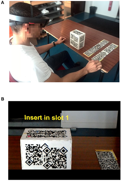
Figure 3. (A) A participant before starting the task. (B) The First-Person View (FPV) on the HoloLens (captured from the Mixed Reality Viewer) displaying textual instruction before starting operation 1.
Training
A training was established before the evaluation in order to reduce the learning effect. Thus, participants underwent a training session of 2 min per [VISUAL] condition, during which the evaluator described the visual overlays and explained the task to be performed. The evaluator also asked the participants to insert the boards. This phase allowed them to get familiar with the task, the three different conditions, as well as with the set-up.
Precisely, they were encouraged to adjust the HoloLens comfortably on their head (improper fitting of a see-through headset can lead to misalignment of the AR elements with respect to the real world). In addition, the evaluator gave them short verbal instructions:
- They were not allowed to move the box (that was fixed on the table) to prevent getting extra visibility cues during tasks;
- They were not allowed to lean forward too much and peek behind the box in order to limit their perception of the actual depth of the box or of the slots' position. An informal poll at the end of the evaluation revealed this was not an issue for the participants.
- They were not allowed to touch the slots in which they had to insert the boards. This, as to avoid any haptic support;
- Every time they finished the task, they have to put the boards back in their initial position on the table, indicated by a label. This, in an attempt to provide the same starting point for all participants and avoid any experimental bias.
Task
During this phase, the participants had to:
(1) First, perform operation 1: insert the first board (with the slots) through the box from left to right.
(2) Then, perform operation 2: a slot number was given to participants orally by the evaluator and through text instruction displaying on the device to avoid any confusion (see Figure 3B). They then inserted the second board into the box from the top and through the first inserted board, using the correct numbered slot. They did this three times, once for each slot according to the number given to them. If a participant inserted the second board into the wrong slot, the insertion was counted as an insertion error, and they proceeded to the next one.
Participants repeated these two operations three times, once per [VISUAL] condition. In this way, each participant performed nine blind insertions altogether. Figure 1 illustrates the first-person view through the HoloLens at different stages of the task.
Post-assessment
Once the task was completed, participants were asked to state how difficult it was to perform the insertion task in each condition by filling out a 5-point Likert scale questionnaire.
The total duration of the evaluation (training, evaluation, and post-assessment) was about 8–9 min for each condition. A small duration was chosen to avoid nausea and loss of attention that could result from prolonged wearing of the HMD, and therefore, could reduce the task performance (Livingston, 2005). Consequently, the total duration to complete the evaluation was ~25 min.
Data Collection
Two participants were removed from the evaluation due to technical problems during the test. In total, 252 trials were registered: 3 [VISUAL] × 3 [SLOT] × 28 participants. For each trial, the task completion time and the number of wrong insertions (i.e., inserting the board into a wrong slot) were logged. In addition, positions of both boards were recorded every 15 frames (4 Hz). Participants' responses to the questionnaire regarding the subjective complexity of the task and their preference regarding each condition were also collected.
From this data, three objective measures were extracted:
(1) TCT: the task completion time of successful insertions only (i.e., when participants inserted the second board in the correct slot).
(2) PWI: the percentage of wrong insertions compared to the total amount of insertions.
(3) AAO: the average amplitude oscillation (shaking) of the second board extracted from X and Y coordinates. It was calculated—for each slot- as the minimum Euclidean distance between the trajectory of the board and the optimal insertion trajectory (i.e., no shaking at all). This provides a measure of how close the trajectory was to the optimal one. Moreover, this measure was calculated during a time interval illustrated in Figure 4. Precisely, the interval started from the moment participants inserted the second board into one slot of the box (P0 in Figure 4), and the moment they inserted it into the corresponding slot of the first board while inside the box (P1 in Figure 4). Finally, a horizontal threshold of 2 cm was defined empirically to remove possible extreme points due to a lack of tracking.
In addition, responses from participants resulted in one subjective measure:
(4) DIF: scores for the difficulty perceived by participants during the assembly.
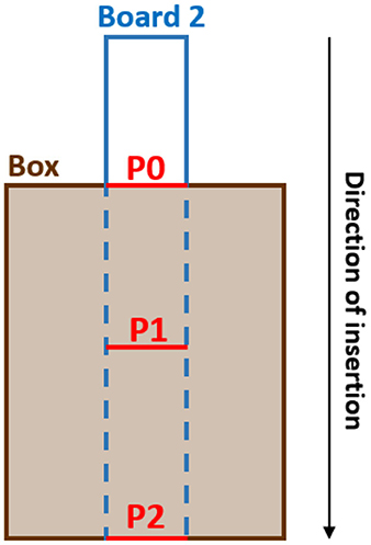
Figure 4. How the time interval was defined in order to calculate AAO measure: P0 represents the point at which participants insert the second board (board 2) into one slot of the box, P1 represents the point where they insert it into the corresponding slot of the first board while inside the box, and P2 represents the point where they complete the task.
Hypotheses
The main goal of this study was to investigate the effectiveness of the AR overlays proposed to highlight the occluded parts during blind insertions. Therefore, it was expected that [VISUAL] conditions would significantly affect the reported measures. Precisely, it was anticipated that the AR visual overlays would help participants to perform the blind task more efficiently compared to the no AR condition. In addition, it was expected that the wireframe overlay would outperform the axes overlay because it provides more complete information on the objects.
Thus, it was hypothesized that:
H1(a): TCT will be the highest in the BAS condition.
H1(b): TCT will be lower in the WIR condition compared to the AXE condition.
H2(a): PWI will be the highest in the BAS condition.
H2(b): PWI will be lower in the WIR condition compared to the AXE condition.
H3(a): AAO will be the highest in the BAS condition.
H3(b): AAO will be lower in the WIR condition compared to the AXE condition.
H4(a): DIF will be the highest in the BAS condition.
H4(b): DIF will be lower in the WIR condition compared to the AXE condition.
Results
In the following, the means and standard deviations are abbreviated by M and α, respectively. The normality of the data was analyzed using visual inspections of the normal QQ-plots in combination with Shapiro-Wilk tests. When data were non-normally distributed, a log 10-transformation was applied to satisfy the assumption of parametric tests. If the data was not normally distributed (i.e., log 10-transformation did not succeed), non-parametric equivalent tests were substituted. The result of the statistical parametric and non-parametric tests for each measure is reported. For statistically significant effects (p < 0.05), Cohen's d effect size estimate r was computed with threshold values 0.1 (small), 0.3 (medium), and 0.5 (large). All the analyses were performed using R version 3.6.0.
The remainder of this section is divided into three parts. The effect of [VISUAL] conditions on the objective measures of performance and the subjective questionnaire are described, respectively, in the first and second parts. The third part investigates the potential order effect.
Effect on the Objective Performance Measures
Figure 5 shows the mean plots for TCT, PWI, and AAO measures. Regarding TCT measure, the mean value for each condition was MBAS = 29.3s (αBAS = 10s), MWIR = 28s (αWIR = 9.1s), MAXE = 32.7s (αAXE = 14.2s). The log10-transformed data was normally distributed (W = 0.98; p = 0.65). Therefore, a one-way repeated measures ANOVA analysis was run that showed no statistical significant difference between [VISUAL] conditions [F(2, 54) = 1.34, p = 0.27), which contradicted H1(a) and H1(b) hypotheses.
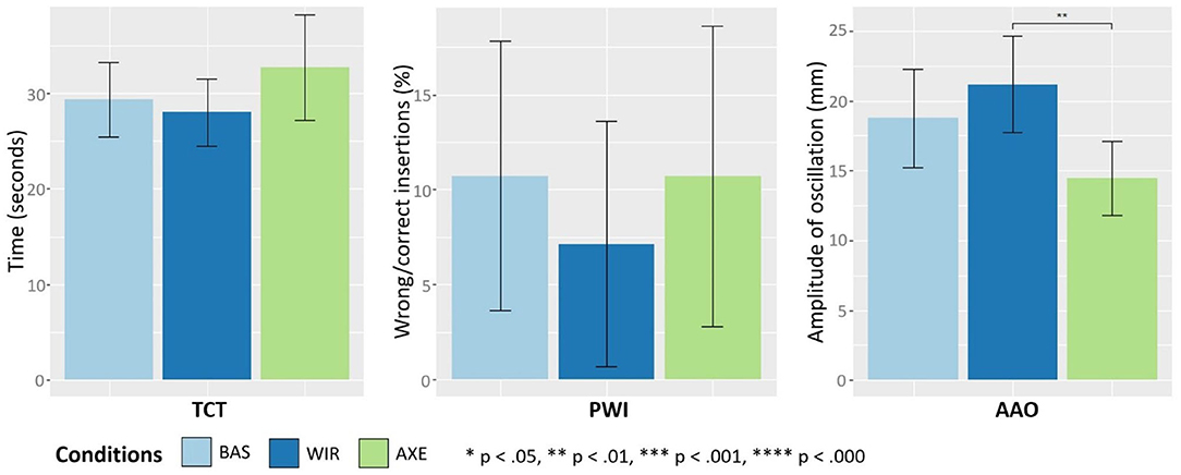
Figure 5. Effect of the [VISUAL] conditions on objective measures. Bar plot indicate mean values. Error bars indicate confidence intervals.
Concerning PWI measure, the average value for each condition was MBAS = 10.7 % (αBAS = 18 %), MWIR = 7.1% (αWIR = 16.6%), MAXE = 10.7% (αAXE = 20.4%). A Shapiro-Wilk test indicated that the data was not-normally distributed, even after applying a log10-transformation (W = 0.56, p < 0.000). Thus, a Friedman test was used that showed no significant difference between the conditions [χ2(2) = 1.76, p = 0.41]. Consequently, H2(a) and H2(b) were rejected.
Finally, concerning AAO measure, the process used to calculate it resulted in removing the data from eight participants due to the lack of points recorded in the specified time interval (detailed in section Data Collection) during their evaluation. Therefore, the analysis below concerns only 20 of the initial 30 participants. The mean value for each condition was MBAS = 18.8 mm (αBAS = 7.6 mm), MWIR = 21.2 mm (αWIR = 7.4 mm), MAXE = 14.4 mm (αAXE = 5.7 mm). The data was normally distributed (W = 0.96; p = 0.07). Therefore, a one-way repeated measures ANOVA analysis was run that showed statistical significant difference between the conditions [F(2, 38) = 4.43, p < 0.05]. Then, paired t-tests with Bonferroni correction were run showing a significant difference between WIR and AXE conditions [t(19) = 3.12, p < 0.01, r = 1.02] with AXE outperforming WIR, which was not expected. In contrast, no statistically significant results were found between BAS and WIR conditions [t(19) = −1, p = 0.33], and between BAS and AXE conditions [t(19) = 1.9, p = 0.07]. Therefore, H3(a) and H3(b) were rejected.
Effect on the Subjective Questionnaire
The average value of DIF (Figure 6) was found to be higher in BAS condition MBAS = 3.25 pts (αBAS = 0.85 pts) compared to both AR conditions (MWIR = 2 pts, αWIR = 0.89 pts; MAXE = 2.37 pts, αAXE = 0.82 pts). The data was not normally distributed (W = 0.94; p < 0.000). A Friedman test was then carried out to compare the mean values for each [VISUAL] condition that showed a significant difference [χ2(2) = 19.63, p < 0.000]. Then, Wilcoxon signed-rank dependent tests with continuity correction were conducted. Results showed statistically significant differences between BAS and WIR conditions (V = 357.5, p < 0.000, r = 1.39), and between BAS and AXE conditions (V = 274.5, p < 0.01, r = 1.04), in both case AR conditions outperformed the baseline condition, which supported H4(a). However, the results between WIR and AXE conditions showed no significant differences (V = 88, p = 0.07), which went against H4(b).
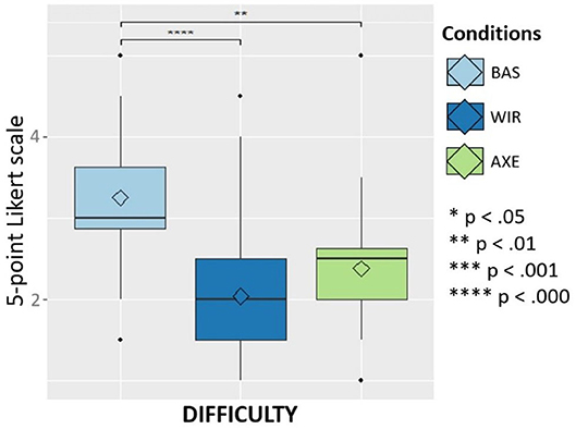
Figure 6. Effect of the [VISUAL] conditions on the difficulty perceived by the participants. The diamond symbol, the line across the box, and the dots represent, respectively, the mean score, the median, and the outliers.
Learning Effect
In order to investigate the learning effect, one-way repeated measures ANOVA analyses and Friedman's tests were computed between the different orders followed by participants during the experiment. The results indicated no statistically significant differences on the four measures of the evaluation, namely, TCT [F(2, 54) = 0.13, p = 0.87], PWI [χ2(2) = 1.33, p = 0.52], AAO [F(2, 38) = 0.55, p = 0.6], and DIF [χ2(2) = 0.17, p = 0.92].
Discussion
An important issue in the evaluation of the three visual conditions was that participants could learn how to perform the insertions more efficiently as they repeat the same task for each condition. This learning effect could bias the results. Yet, no statistical significant results were found between the different orders of conditions. Therefore, one can conclude that preventive measures were enough to mitigate the learning effect.
The comparative analysis performed on task completion time and percentage of wrong insertions indicated that augmenting the user's vision, with both wireframe and axe overlays, did not lead to statistically significant objective performance improvement in comparison with the no-AR baseline situation. The most likely reason could be the tracking issues met during the experiment. Even with the use of the Vuforia plug-in and visual targets with high satisfactory requirements, the system experienced some loss of tracking of the assembly objects (mostly the boards) when they were too much covered by participants' hands. Another potential reason could be the low resolution of the cameras of the HoloLens that negatively affected the quality of the Vuforia tracking system (Evans et al., 2017). Livingston (2005) highlighted the lack of robustness of current tracking algorithms. This is a common software limitation of AR display devices that has to be resolved in the future in order to provide robust AR assembly assistance. Finally, yet importantly, participants could also experience an incorrect perception of depth (Swan et al., 2015). This could result in a misinterpretation of the overall assembly information augmented on the real objects, and therefore, reduce the performance of users. Nevertheless, because of the lack of familiarity of the average user with this type of device (the perceived average skill with HMD prior to the experiment reported as only 1.83 on a scale of 5 points Likert scale), one can be comforted by the fact the performance was, at least, not degraded by the current limitations of HMDs [limited field of vision, imprecise tracking, etc. (Livingston, 2005)].
User performance depends also on hardware features (Nee et al., 2012). Therefore, it is necessary to ensure that users feel comfortable using AR devices. In this experiment, participants reported a good acceptance of the system despite its shortcomings. They unanimously perceived both wireframe and axes mode as easier than the default mode. Moreover, the questionnaire indicates a strong preference of participants for both wireframe and axes mode: participants were asked to rank the assembling modes in order of preference from 1 to 3 (rank 1 being their favorite). Results revealed that 42% of the participants preferred the wireframe mode, 36% preferred the axes mode and 22% preferred the default mode. It validated the hypothesis regarding the subjective usefulness of both AR visualizations for blind insertion tasks.
The most interesting result concerned trajectory. Indeed, axes overlay resulted in a smaller degree of oscillation compared to wireframe overlay. In other words, using the axes overlays participants performed smoother trajectories, meaning that more abstract visualization aids can simplify the perception of the assembly scene and reduce the information to be processed by users, leading to better performance. This parameter could prove useful to build future evaluation systems and possibly apply our findings to real-world assembly tasks.
Informal post-interviews also confirmed the potential value of the axes overlay. It was reported that in some cases, overlaying exhaustive geometric information (wireframe condition) might become counterproductive and actually obfuscate important visual assembly cues. Furthermore, some participants reported the perception of an offset in the wireframe condition, which could be due to the absence of eye tracking calibration during the experiment (since inter-eye distances vary among participants, this may have contributed to displayed errors). This offset in itself was very small and did not affect the participants' understanding of augmented information. However, although participants noticed it only in the wireframe condition, it existed also in axes condition, except that, with wireframe overlay, the virtual content represented 3D objects superimposed on the real objects, which made the offset easier to notice. Whereas, with axes overlay, the guides were abstract objects with no real references making it more difficult to notice the offset. Thus, simplified, more abstract features with high information value (holes, axes, and slots, etc.) were preferred. An obvious design recommendation might be, therefore, to modify the wireframe overlay to display only the truly useful parts of the assembly instead of all the outlines and inner parts of objects, which can at times obstruct the real-world view. More specifically, it could be interesting to design a “dynamic” wireframe overlay relying on a context-aware approach to display only the relevant information at each stage of the blind assembly process (Zhu et al., 2013; Khuong et al., 2014).
To summarize, both AR visualizations were preferred and perceived as more useful compared to the no AR baseline situation. Conversely, objective indicators suggest no significant gain in performance. This contrast between objective and subjective results can be due to the relative simplicity of the prototypical peg-in-hole task design. To some extent, choosing a task suitable for an AR-based assistance system is still an open research issue since it relies on a good user interface, but before such an interface is developed, one is not sure if the task is suitable (Livingston, 2005). Nevertheless, an outcome of the experiment is the necessity to design tasks that are more difficult and build objects that are more complex. This would allow studying the effect of increasing complexity on both user performance and satisfaction, with or without visual AR (Radkowski et al., 2015).
Conclusion and Perspectives
Although many AR-based assembly support systems have been proposed in academic research and industry, the occlusion issue that occurs during the process of blind assembly tasks remained an unexplored topic.
In this paper, an AR prototype set-up was designed specifically for blind peg-in-hole insertions tasks. It consisted of assembly objects overlaid with assistance information presented with the AR personal see-through device HoloLens coupled with a Vuforia plug-in for tracking purposes. Precisely, two AR visualization modes that directly overlaid on the physical objects were proposed: one that displays all the outlines and inner parts of the objects thus providing an inside view of the occluded parts referred to as the wireframe overlay, and another one in which only the axes of the objects and their slots were rendered indicating how to align the different parts during the assembly, referred to as the axes overlay.
Special care was given not to distract or obstruct the user by designing a self-contained, standalone, and lightweight set-up. Particular attention was also paid to user interaction by providing natural interaction while manipulating the assembly objects (Carmigniani et al., 2011).
A user experiment was then conducted to comparatively evaluate both AR overlays with a no-AR baseline condition. The evaluation included objective performance measures represented by task completion time, percentage of wrong insertions, and the extent to which the trajectory of the objects oscillated, as well a subjective questionnaire reporting the degree of difficulty of the task and the perceived user preference.
Results indicated that participants perceived AR overlays as making them more effective at performing their tasks. However, objectives measures did not validate these results and showed no significant difference between AR aids and the baseline situation. This could be mainly due to the loss of tracking of the assembly objects when they were too much covered by participants' hands. Another potential cause highlighted by the experiment could be the low resolution of the cameras of the HoloLens, confirming some studies reporting that the low tracking accuracy of the HoloLens prevents the deliverance of robust AR assembly experiences (Evans et al., 2017; Palmarini et al., 2018).
With the improvement of tracking algorithms and more accurate response time, future versions of the HoloLens and other AR see-through headsets should more effectively assist assembly operations. Nevertheless, in the meantime, it would be interesting to add an external camera with higher resolution to improve tracking. An additional camera would also allow the implementation of another AR visualization: “the third-person view” which would consist in an indirect view of the assembly objects (similar to a side-view mirror). The next study will consist in designing such a set-up and compare this new visualization with the current AR overlays. In addition, care must be taken to calibrate eye tracking which is necessary to provide more accurate depth presentation and avoid bias the results.
Moreover, since the assembly environment is assumed to be known, it could also be interesting to improve the AR visualizations presented in this paper in order to provide a more effective way of notifying the user when the appropriate insertion depth has been reached.
Apart from improved hardware and software development, another future research direction would be to study the effectiveness of this AR-based assembly system with respect to a particular blind assembly task designed with certain degrees of complexity. The evaluation would include performance and cognitive measures such as the mental and physical workload, as well as monitor the user satisfaction and acceptance of such a system.
Thus, the presented study provided a first insight into the design of AR visualizations for blind assembly support systems. It also highlighted that, despite being a promising device, the HoloLens is not ready yet for deployment in a factory assembly environment.
Data Availability Statement
The raw data supporting the conclusions of this article will be made available by the authors, without undue reservation.
Ethics Statement
Ethical approval was not provided for this study on human participants because no local ethics committee existed at the time of the experiment. However, the Helsinki protocol was followed. The patients/participants provided their written informed consent to participate in this study.
Author Contributions
NK reviewed the literature, implemented the set-up, run the experiment, and evaluated the data collected. JV provided the original idea and interface conception, evaluation procedure, and overall work supervision. PB provided overall work supervision. All authors contributed to the article and approved the submitted version.
Funding
This research was partially supported by RTA Digiteo and Labex DigiCosme (Idex Paris-Saclay ANR-11-IDEX-0003-02), and by EquipEx DIGISCOPE (ANR-10-EQPX-26-01) operated by the French National Research Agency (ANR), as part of the program Investissements d'Avenir.
Conflict of Interest
The authors declare that the research was conducted in the absence of any commercial or financial relationships that could be construed as a potential conflict of interest.
Supplementary Material
The Supplementary Material for this article can be found online at: https://www.frontiersin.org/articles/10.3389/frvir.2020.588217/full#supplementary-material
Footnotes
1. ^Arvika, http://www.arvika.de/.
2. ^ARTESAS, http://www.mip.informatik.uni-kiel.de/tiki-index.php?page=artesas.
3. ^The objects were manufactured within our in-house FabLab facilities to allow for an iterative fabrication process.
4. ^https://developer.microsoft.com/en-us/windows/holographic/unity_development_overview.
5. ^Configuring a Vuforia app for Hololens https://docs.microsoft.com/fr-fr/windows/mixed-reality/vuforia-development-overview.
6. ^Vuforia AR platform, PTC Inc., United States https://library.vuforia.com/articles/Solution/Optimizing-Target-Detection-and-Tracking-Stability.html.
References
Abdullah, M. W., Roth, H., Weyrich, M., and Wahrburg, J. (2015). An approach for peg-in-hole assembling using intuitive search algorithm based on human behavior and carried by sensors guided industrial robot. IFAC PapersOnLine 48, 1476–1481. doi: 10.1016/j.ifacol.2015.06.295
Arbeláez, J. C., Viganò, R., and Osorio-Gómez, G. (2019). Haptic augmented reality (HapticAR) for assembly guidance. IJIDeM 13, 673–687. doi: 10.1007/s12008-019-00532-3
Ardito, C., Buono, P., Costabile, M. F., and Desolda, G. (2015). Interaction with large displays: a survey. ACM Comput. Sur. 47, 1–38. doi: 10.1145/2682623
Avery, B., Piekarski, W., and Thomas, B. H. (2007). “Visualizing occluded physical objects in unfamiliar outdoor augmented reality environments,” in 2007 6th IEEE and ACM International Symposium on Mixed and Augmented Reality (Nara: IEEE), 285–286. doi: 10.1109/ISMAR.2007.4538869
Avery, B., Sandor, C., and Thomas, B. H. (2009). “Improving spatial perception for augmented reality x-ray vision,” in 2009 IEEE Virtual Reality Conference (Lafayette, LA: IEEE), 79–82. doi: 10.1109/VR.2009.4811002
Azuma, R., Baillot, Y., Behringer, R., Feiner, S., Julier, S., and MacIntyre, B. (2001). Recent advances in augmented reality. IEEE Comput. Graph. Appl. 21, 34–47. doi: 10.1109/38.963459
Azuma, R. T. (1997). A survey of augmented reality. Presence 6, 355–385. doi: 10.1162/pres.1997.6.4.355
Baird, K. M., and Barfield, W. (1999). Evaluating the effectiveness of augmented reality displays for a manual assembly task. Virtual Real. 4, 250–259. doi: 10.1007/BF01421808
Bajura, M., Fuchs, H., and Ohbuchi, R. (1992). Merging virtual objects with the real world: Seeing ultrasound imagery within the patient. ACM Siggraph Comput. Graphics 26, 203–210. doi: 10.1145/142920.134061
Bane, R., and Hollerer, T. (2004). “Interactive tools for virtual x-ray vision in mobile augmented reality,” in Third IEEE and ACM International Symposium on Mixed and Augmented Reality (Arlington: IEEE), 231–239.
Bashir, A. M., Bicker, R., and Taylor, P. M. (2004). “An investigation into different visual/tactual feedback modes for a virtual object manipulation task,” in Proceedings of the 2004 ACM SIGGRAPH International Conference on Virtual Reality Continuum and Its Applications in Industry (Singapore), 359–362.
Blattgerste, J., Strenge, B., Renner, P., Pfeiffer, T., and Essig, K. (2017). “Comparing conventional and augmented reality instructions for manual assembly tasks,” in Proceedings of the 10th International Conference on Pervasive Technologies Related to Assistive Environments (Rhodes), 75–82. doi: 10.1145/3056540.3056547
Carmigniani, J., Furht, B., Anisetti, M., Ceravolo, P., Damiani, E., and Ivkovic, M. (2011). Augmented reality technologies, systems and applications. Multimed. Tools Appl. 51, 341–377. doi: 10.1007/s11042-010-0660-6
Caudell, T. P., and Mizell, D. W. (1992). “Augmented reality: an application of heads-up display technology to manual manufacturing processes,” in Proceedings of the Twenty-Fifth Hawaii International Conference on System Sciences (Kauai, HI), 659–669. doi: 10.1109/HICSS.1992.183317
Chhatpar, S. R., and Branicky, M. S. (2001). “Search strategies for peg-in-hole assemblies with position uncertainty,” in Proceedings 2001 IEEE/RSJ International Conference on Intelligent Robots and Systems. Expanding the Societal Role of Robotics in the the Next Millennium (Cat. No. 01CH37180) (Maui, HI: IEEE), 1465–1470).
Curtis, D., Mizell, D., Gruenbaum, P., and Janin, A. (1999). “Several devils in the details: making an AR application work in the airplane factory,” in Proceedings of the International Workshop Augmented Reality (San Francisco, CA), 47–60.
Doil, F., Schreiber, W., Alt, T., and Patron, C. (2003). “Augmented reality for manufacturing planning,” in Proceedings of the workshop on Virtual environments (Zurich), 71–76. doi: 10.1145/769953.769962
Evans, G., Miller, J., Pena, M. I., MacAllister, A., and Winer, E. (2017). “Evaluating the Microsoft HoloLens through an augmented reality assembly application,” in Degraded Environments: Sensing, Processing, and Display 2017 (International Society for Optics and Photonics), 101970V.
Funk, M., Heusler, J., Akcay, E., Weiland, K., and Schmidt, A. (2016a). “Haptic, auditory, or visual? Towards optimal error feedback at manual assembly workplaces,” in Proceedings of the 9th ACM International Conference on PErvasive Technologies Related to Assistive Environments (Corfu), 1–6. doi: 10.1145/2910674.2910683
Funk, M., Kosch, T., Greenwald, S. W., and Schmidt, A. (2015). “A benchmark for interactive augmented reality instructions for assembly tasks,” in Proceedings of the 14th International Conference on Mobile and Ubiquitous Multimedia (Linz), 253–257. doi: 10.1145/2836041.2836067
Funk, M., Kosch, T., and Schmidt, A. (2016b). “Interactive worker assistance: comparing the effects of in-situ projection, head-mounted displays, tablet, and paper instructions,” in Proceedings of the 2016 ACM International Joint Conference on Pervasive and Ubiquitous Computing (Heidelberg), 934–939. doi: 10.1145/2971648.2971706
Furlan, R. (2016). The future of augmented reality: hololens-microsoft's ar headset shines despite rough edges [resources_tools and toys]. IEEE Spectrum 53, 21–21. doi: 10.1109/MSPEC.2016.7473143
Henderson, S. J., and Feiner, S. K. (2011). “Augmented reality in the psychomotor phase of a procedural task,” in 2011 10th IEEE International Symposium on Mixed and Augmented Reality (Basel: IEEE), 191–200. doi: 10.1109/ISMAR.2011.6092386
Hillers, B., Aiteanu, D., and Gräser, A. (2004). “Augmented reality-helmet for the manual welding process,” in Virtual and Augmented Reality Applications in Manufacturing (London: Springer), 361–381. doi: 10.1007/978-1-4471-3873-0_18
Horejší, P. (2015). Augmented reality system for virtual training of parts assembly. Proc. Eng. 100, 699–706. doi: 10.1016/j.proeng.2015.01.422
Hou, L., and Wang, X. (2013). A study on the benefits of augmented reality in retaining working memory in assembly tasks: a focus on differences in gender. Autom. Constr. 32, 38–45. doi: 10.1016/j.autcon.2012.12.007
Khuong, B. M., Kiyokawa, K., Miller, A., La Viola, J. J., Mashita, T., and Takemura, H. (2014). “The effectiveness of an AR-based context-aware assembly support system in object assembly,” in 2014 IEEE Virtual Reality (VR) (Minneapolis, MN: IEEE), 57–62.
Kitagawa, M., and Yamamoto, T. (2011). “3D puzzle guidance in augmented reality environment using a 3D desk surface projection,” in 2011 IEEE Symposium on 3D User Interfaces (3DUI) (Singapour: IEEE), 133–134. doi: 10.1109/3DUI.2011.5759241
Korn, O., Schmidt, A., and Hörz, T. (2013). “Augmented manufacturing: a study with impaired persons on assistive systems using in-situ projection,” in Proceedings of the 6th International Conference on PErvasive Technologies Related to Assistive Environments, 1–8. doi: 10.1145/2504335.2504356
Lim, T., Ritchie, J. M., Dewar, R. G., Corney, J. R., Wilkinson, P., Calis, M., et al. (2007). Factors affecting user performance in haptic assembly. Virtual Real. 11, 241–252. doi: 10.1007/s10055-007-0072-8
Livingston, M. A. (2005). Evaluating human factors in augmented reality systems. IEEE Comput. Graph. Appl. 25, 6–9. doi: 10.1109/MCG.2005.130
Markov-Vetter, D., and Staadt, O. (2013). “A pilot study for augmented reality supported procedure guidance to operate payload racks on-board the international space station,” in 2013 IEEE International Symposium on Mixed and Augmented Reality (ISMAR) (IEEE), 1–6. doi: 10.1109/ISMAR.2013.6671832
Nakanishi, M., Ozeki, M., Akasaka, T., and Okada, Y. (2007). “Human factor requirements for applying augmented reality to manuals in actual work situations,” in 2007 IEEE International Conference on Systems, Man and Cybernetics (Montréal, QC: IEEE), 2650–2655.
Navab, N., Heining, S. M., and Traub, J. (2009). Camera augmented mobile C-arm (CAMC): calibration, accuracy study, and clinical applications. IEEE Trans. Med. Imaging. 29, 1412–1423. doi: 10.1109/TMI.2009.2021947
Nee, A. Y., Ong, S. K., Chryssolouris, G., and Mourtzis, D. (2012). Augmented reality applications in design and manufacturing. CIRP Ann. 61, 657–679. doi: 10.1016/j.cirp.2012.05.010
Nilsson, S., and Johansson, B. (2007). “Fun and usable: augmented reality instructions in a hospital setting,” in Proceedings of the 19th Australasian Conference on Computer-Human Interaction: Entertaining User Interfaces (Adelaide), 123–130.
Nishihara, A., and Okamoto, J. (2015). “Object recognition in assembly assisted by augmented reality system,” in 2015 SAI Intelligent Systems Conference (IntelliSys) (London: IEEE), 400–407. doi: 10.1109/IntelliSys.2015.7361172
Ojer, M., Alvarez, H., Serrano, I., Saiz, F. A., Barandiaran, I., Aguinaga, D., et al. (2020). Projection-based augmented reality assistance for manual electronic component assembly processes. Appl. Sci. 10:796. doi: 10.3390/app10030796
Okamoto, J., and Nishihara, A. (2016). “Assembly assisted by augmented reality (A 3 R),” in Intelligent Systems and Applications (Cham: Springer), 281–300. doi: 10.1007/978-3-319-33386-1_14
Ong, S. K., Yuan, M. L., and Nee, A. Y. C. (2008). Augmented reality applications in manufacturing: a survey. Int. J. Prod. Res. 46, 2707–2742. doi: 10.1080/00207540601064773
Palmarini, R., Erkoyuncu, J. A., Roy, R., and Torabmostaedi, H. (2018). A systematic review of augmented reality applications in maintenance. Robot. Comput. Integr. Manuf. 49, 215–228. doi: 10.1016/j.rcim.2017.06.002
Park, H., Bae, J. H., Park, J. H., Baeg, M. H., and Park, J. (2013). “Intuitive peg-in-hole assembly strategy with a compliant manipulator,” in IEEE ISR 2013 (Seoul: IEEE), 1–5. doi: 10.1109/ISR.2013.6695699
Pathomaree, N., and Charoenseang, S. (2005). “Augmented reality for skill transfer in assembly task,” ROMAN 2005. IEEE International Workshop on Robot and Human Interactive Communication, 2005 (Nashville, TN), 500–504. doi: 10.1109/ROMAN.2005.1513829
Perret, J., Kneschke, C., Vance, J., and Dumont, G. (2013). Interactive assembly simulation with haptic feedback. Assem. Autom. 33, 214–220. doi: 10.1108/AA-03-2013-017
Petzold, B., Zaeh, M. F., Faerber, B., Deml, B., Egermeier, H., Schilp, J., et al. (2004). A study on visual, auditory, and haptic feedback for assembly tasks. Presence 13, 16–21. doi: 10.1162/105474604774048207
Radkowski, R., Herrema, J., and Oliver, J. (2015). Augmented reality-based manual assembly support with visual features for different degrees of difficulty. Int. J. Hum. Comput. Interact. 31, 337–349. doi: 10.1080/10447318.2014.994194
Regenbrecht, H., Baratoff, G., and Wilke, W. (2005). Augmented reality projects in the automotive and aerospace industries. IEEE Comput. Graph. Appl. 25, 48–56. doi: 10.1109/MCG.2005.124
Reiners, D., Stricker, D., Klinker, G., and Müller, S. (1999). “Augmented reality for construction tasks: Doorlock assembly,” in Proceedings of the International Workshop on Augmented Reality: Placing Artificial Objects in Real Scenes: placing artificial objects in real scenes (AK Peters, Ltd.), 31–46.
Reinhart, G., and Patron, C. (2003). Integrating augmented reality in the assembly domain-fundamentals, benefits and applications. CIRP Ann. 52, 5–8. doi: 10.1016/S0007-8506(07)60517-4
Robertson, C. M., MacIntyre, B., and Walker, B. N. (2008). “An evaluation of graphical context when the graphics are outside of the task area,” in 2008 7th IEEE/ACM International Symposium on Mixed and Augmented Reality (Cambrdge: IEEE), 73–76. doi: 10.1109/ISMAR.2008.4637328
Schwald, B., Figue, J., Chauvineau, E., Vu-Hong, F., Robert, A., and Arbolino, M. (2001). STARMATE: Using augmented reality technology for computer guided maintenance of complex mechanical elements. Ework ECommerce 1, 196–202. Available online at: http://publica.fraunhofer.de/documents/N-7375.html
Seok, K. H., and Kim, Y. S. (2008). “A study on providing prompt assembly information using AR manual,” 2008 Third International Conference on Convergence and Hybrid Information Technology (Busan), 693–695. doi: 10.1109/ICCIT.2008.304
Seth, A., Su, H. J., and Vance, J. M. (2006). “SHARP: a system for haptic assembly and realistic prototyping,” in ASME 2006 International Design Engineering Technical Conferences and Computers and Information in Engineering Conference (American Society of 748 Mechanical Engineers Digital Collection), 905–912. doi: 10.1115/DETC2006-99476
Sims, D. (1994). “New realities in aircraft design and manufacture,” in IEEE Computer Graphics and Applications (IEEE), 91. doi: 10.1109/38.267487
Sivaraman, S., and Trivedi, M. M. (2013). Looking at vehicles on the road: A survey of vision-based vehicle detection, tracking, and behavior analysis. IEEE trans. Intell. Transp. Syst. 14, 1773–1795. doi: 10.1109/TITS.2013.2266661
Swan, J. E., Singh, G., and Ellis, S. R. (2015). Matching and reaching depth judgments with real and augmented reality targets. IEEE Trans. Vis. Comput. Graph, 21, 1289–1298. doi: 10.1109/TVCG.2015.2459895
Syberfeldt, A., Danielsson, O., Holm, M., and Wang, L. (2015). Visual assembling guidance using augmented reality. Proc. Manuf. 1, 98–109. doi: 10.1016/j.promfg.2015.09.068
Tabrizi, L. B., and Mahvash, M. (2015). Augmented reality-guided neurosurgery: accuracy and intraoperative application of an image projection technique. J. Neurosurg. 123, 206–211. doi: 10.3171/2014.9.JNS141001
Tang, A., Owen, C., Biocca, F., and Mou, W. (2003). “Comparative effectiveness of augmented reality in object assembly,” in Proceedings of the SIGCHI Conference on Human Factors in Computing Systems (Florida), 73–80. doi: 10.1145/642611.642626
Tching, L., Dumont, G., and Perret, J. (2010). Interactive simulation of CAD models assemblies using virtual constraint guidance. Int. J. Interac. Design Manuf. 4, 95–102. doi: 10.1007/s12008-010-0091-7
Unger, B. J., Nicolaidis, A., Berkelman, P. J., Thompson, A., Lederman, S., Klatzky, R. L., et al. (2002). “Virtual peg-in-hole performance using a 6-dof magnetic levitation haptic device: Comparison with real forces and with visual guidance alone,” in Proceedings 10th Symposium on Haptic Interfaces for Virtual Environment and Teleoperator Systems (Orlando, FL: HAPTICS; IEEE), 263–270.
Valentini, P. P. (2009). Interactive virtual assembling in augmented reality. Int. J. Interac. Design Manuf. 3, 109–119. doi: 10.1007/s12008-009-0064-x
Wang, X., Ong, S. K., and Nee, A. Y. (2016). A comprehensive survey of augmented reality assembly research. Adv. Manuf. 4, 1–22. doi: 10.1007/s40436-015-0131-4
Webel, S., Bockholt, U., Engelke, T., Gavish, N., Olbrich, M., and Preusche, C. (2013). An augmented reality training platform for assembly and maintenance skills. Rob. Auton. Syst. 61, 398–403. doi: 10.1016/j.robot.2012.09.013
Wildenbeest, J. G., Abbink, D. A., Heemskerk, C. J., Van Der Helm, F. C., and Boessenkool, H. (2012). The impact of haptic feedback quality on the performance of teleoperated assembly tasks. IEEE Trans. Haptics, 6, 242–252. doi: 10.1109/TOH.2012.19
Yuan, M. L., Ong, S. K., and Nee, A. Y. (2004). The virtual interaction panel: an easy control tool in augmented reality systems. Comput. Anim. Virtual Worlds 15, 425–432. doi: 10.1002/cav.46
Yuan, M. L., Ong, S. K., and Nee, A. Y. C. (2008). Augmented reality for assembly guidance using a virtual interactive tool. Int. J. Prod. Res. 46, 1745–1767. doi: 10.1080/00207540600972935
Zang, X., Weng, D., Wang, Y., and Liu, Y. (2009). “Augmented reality based surgery navigation system,” in 2009 International Conference on Optical Instruments and Technology: Optoelectronic Imaging and Process Technology (International Society for Optics and Photonics), 75132T.
Zauner, J., Haller, M., Brandl, A., and Hartman, W. (2003). “Authoring of a mixed reality assembly instructor for hierarchical structures,” in The Second IEEE and ACM International Symposium on Mixed and Augmented Reality (Tokyo: IEEE), 237–246.
Zenati, N., Zerhouni, N., and Achour, K. (2004). “Assistance to maintenance in industrial process using an augmented reality system,” in 2004 IEEE International Conference on Industrial Technology (IEEE ICIT'04), 848–852.
Zhang, K., Shi, M., Xu, J., Liu, F., and Chen, K. (2017). Force control for a rigid dual peg-in-hole assembly. Assem. Autom. 37, 200–207. doi: 10.1108/AA-09-2016-120
Zhou, F., Duh, H. B. L., and Billinghurst, M. (2008). “Trends in augmented reality tracking, interaction and display: A review of ten years of ISMAR,” in 2008 7th IEEE/ACM International Symposium on Mixed and Augmented Reality (IEEE), 193–202.
Keywords: augmented reality guidance, augmented reality-based assembly, blind insertion, occlusion issue, user experience (UX), subjective and objective evaluation
Citation: Khenak N, Vézien J and Bourdot P (2020) Effectiveness of Augmented Reality Guides for Blind Insertion Tasks. Front. Virtual Real. 1:588217. doi: 10.3389/frvir.2020.588217
Received: 28 July 2020; Accepted: 15 October 2020;
Published: 19 November 2020.
Edited by:
Mar Gonzalez-Franco, Microsoft Research, United StatesReviewed by:
Hiroyuki Kajimoto, The University of Electro-Communications, JapanWeixin Si, Shenzhen Institutes of Advanced Technology (CAS), China
Copyright © 2020 Khenak, Vézien and Bourdot. This is an open-access article distributed under the terms of the Creative Commons Attribution License (CC BY). The use, distribution or reproduction in other forums is permitted, provided the original author(s) and the copyright owner(s) are credited and that the original publication in this journal is cited, in accordance with accepted academic practice. No use, distribution or reproduction is permitted which does not comply with these terms.
*Correspondence: Jeanne Vézien, dmV6aWVuQGxpbXNpLmZy