 Shi Yiting
 Zhang Liting
- School of Energy and Power Engineering, Shanghai University of Electric Power, Shanghai, China
In the contemporary era, the scarcity and strain of energy resources, combined with the pursuit of their efficient utilization, have posed critical challenges to the global community. Energy storage technology provides a solution to defer the utilization of heat or cold, thus tackling the root cause of energy shortages. Significantly, the integration of new energy sources has further enhanced the demand for energy storage. In contrast, the cost of heat storage is only one-tenth of that of electricity storage, which endows heat storage with more promising application prospects. Within the domain of heat storage, phase change heat storage has emerged as a prominent research focus due to its unique advantages such as high heat storage density, compact volume, and convenient control and matching capabilities. Consequently, we have made efforts to investigate the characteristics of phase change heat storage and improve heat transfer efficiency. Specifically, based on CFD simulation software and the enthalpy method mathematical model, a numerical model of the phase transformation process of tubular paraffin coupled with thermal conductivity and natural convection was established, and its heat absorption and heat release characteristics were simulated. The results indicate that the phase transition interface is symmetrical in general, but asymmetrical in the upper and lower parts, with the paraffin at the top having the fastest melting speed. To enhance the heat absorption and release process of phase change, the eccentric sleeve and fin were introduced. With the increase of eccentricity, the circulating flow range caused by natural convection expands. This is because the amount of paraffin in the lower part decreases and the thermal resistance reduces, which accelerates the melting speed. Moreover, increasing the eccentricity within a certain range is beneficial to accelerating the melting process. The addition of fins can significantly shorten the melting time of paraffin wax. Also, increasing the fin height and fin width can effectively reduce the melting time. However, as the fin height and fin width increase, the shortening gradient gradually decreases.
1 Introduction
In recent years, with the progress of urbanization, huge energy consumption has brought severe environmental crisis. To achieve China’s “carbon neutrality” and “carbon peak” goals, lead the innovation of green technology, adapt to the new energy trend, and promote sustainable development, we need to abandon inefficiencies and vigorously develop renewable clean energy and improve energy storage technology. A new era of increased energy efficiency. Energy storage can realize the delayed use of heat or cold, and alleviate the energy shortage from the root cause, especially the introduction of new energy has increased the demand for energy storage. On the one hand, energy storage can smooth the volatility of the generation side and the load side, and assume the heavy responsibility in the new power system. In the past decade, the cost of photoelectric and wind power in China has declined rapidly, laying the foundation for the rapid increase of installed capacity. However, photoelectric and wind power have intermittent and unstable characteristics, and can not directly meet the needs of the power grid and users, which has become the main obstacle to further expanding their scale. Energy storage is the use of special devices and systems to store energy, release energy when needed, and realize the transfer of energy in time and/or space, which is a must for promoting large-scale renewable energy access to the grid (Wang and Cheng, 2024). On the other hand, energy storage is an indispensable infrastructure in new power systems. Among many flexible resources, energy storage, due to its rapid response, plays a key role in auxiliary services such as frequency modulation and black start of the power grid, and is of vital significance to the structure, technology, trading and scheduling of the new power system, further ensuring the safety and flexibility of power operation. It will play a crucial role in the construction of new power systems and urban energy planning at the national and provincial levels (Chen et al., 2024).
Relatively speaking, the cost of heat storage is only 1/10 of the cost of electricity storage, and it has better application prospects. There are numerous examples of existing heat storage technologies being applied to engineering and practical problems, such as building energy conservation, recycling of metallurgical waste heat and solar water heating systems (Zou, 2020). In heat storage, phase change heat storage has become the focus of research because of its significant advantages such as high heat storage density, small volume and easy to control and match. Zhang et al. (2013) put forward the enthalpy method model to solve the phase transition problem. The simulation results show that the inlet temperature of hot fluid plays a dominant role in the whole process of melting phase transition, and the influence of the flow rate of hot fluid is not as important as the influence of the inlet temperature of hot fluid on the process of melting phase transition. Factors such as the initial temperature and thickness of the material itself also affect the whole process of melting phase transformation. Zou (2020) simulated the melting process of phase change materials in plate heat storage devices under different working conditions by CFD simulation software FLUENT. The research showed that natural convection conditions played a crucial role in the entire melting phase change process, and pointed out that the thermal efficiency of phase change process of vertically placed heat storage devices was much higher than that of horizontal storage devices under the same conditions. Abdulrahman et al. (2019) also observed the heat absorption and release characteristics of paraffin phase change materials in rectangular heat exchangers under different Reynolds numbers on the basis of CFD numerical simulation. The results show that the increasing Reynolds number of hot fluid is positively correlated with the heat transfer performance of PCM during the process of melting phase change, indicating that the increasing Reynolds number of hot fluid will enhance the heat transfer of PCM and lead to the rapid melting of PCM. Then, a mathematical model on the basis of the principle of similarity has been established, with a smaller calculation ratio, which broadened the channel for future research.
To enhancing heat transfer, on the one hand, compared with methods such as embedding fins, embedding foam, and dispersing nanoparticles, the embedding of fins is popular due to its low cost and good effect. During the melting process, (Liu et al., 2019) commenced their research from the simulation analysis of the heat absorption and release phase change process in finned-tube heat storage devices. By means of altering the thickness and width of the fins, they obtained the static temperature distribution contour plots, the liquid fraction variation curves, and the trend curves of the time required for the complete melting of the phase change material in the finned tube corresponding to different fin thicknesses and widths at the same moment as time progressed continuously. Complementary to this research, (Yuan et al., 2018) through numerous experimental verifications, demonstrated that during the melting process of the phase change material, increasing the number of fins within a certain range could significantly enhance the thermal conductivity of the phase change material, and the circulating flow generated by natural convection would render the temperature and material distribution more uniform, exerting a positive and beneficial effect on the entire phase change process and effectively improving the heat storage efficiency. Furthermore, in an attempt to identify the optimal range for varying fin parameters, (Eslami et al., 2021) reviewed the enhanced heat transfer effects of fin geometric parameters such as fin number, thickness, and length on shell-and-tube heat exchange systems and conducted optimization. They reached the conclusion that increasing the fin number and length could promote heat transfer; however, there exists an optimal value, beyond which an excessive number of fins might inhibit convection. The fin thickness has a relatively minor adverse impact on the charging time and no significant impact on the discharging time. Subsequently, the placement position, angle, and shape of the fins were also taken into consideration. (Zhu et al., 2022) focused on novel fin angles such as spiral, tree-shaped, and Y-shaped fins and explored the diverse spatial position distributions and optimal fin array designs within different heat accumulators such as triple-tube, cylindrical shell-and-tube, multi-tube single-shell, and rectangular heat accumulators. Thereby, they determined the optimal fin number values for different heat accumulator types and optimized the size and shape of the fins, providing valuable insights for further research and optimization work in this field.
However, the installation of fins or the addition of metal foams may lead to adverse consequences such as the weakening of the development of natural convection compared to the original situation and a reduction in the heat storage capacity. Therefore, when modifying the geometric structure of the heat storage device, a trade-off between advantages and disadvantages is necessary. Another common measure for external factors in the heat exchange process to enhance heat exchange is to upgrade and optimize the geometric structure of the heat storage device, such as changing the eccentricity. This approach can also have a significant impact on the phase change material in the liquid state. For instance, based on numerical simulations, (DarziA et al., 2010) obtained the influence of unconventional eccentric structures on phase change parameters. This research indicates that the eccentric structure has a substantial impact on the phase change material in the middle and late stages, and the melting rate is also improved compared to the original conventional structure. Moreover, when the inlet parameters such as the inlet temperature and inlet flow rate are kept constant, as the eccentricity increases from 0 to 0.25 and from 0.5 to 0.75, the time required for the complete melting of the phase change material decreases by 33%, 57%, and 64% respectively. Kumar and Verma (2020) through experimental and numerical simulation methods, discovered that specific fin angle arrangements are more effective in mitigating the adverse effects of weak heat conduction in the bottom annulus, thereby enhancing the melting performance. Meanwhile, they proved that an increase in the Stefan number can significantly improve the melting performance and generate a synergistic effect with the eccentric configuration. When the maximum eccentricity ratio is 0.7, the volume of the melted PCM increases, the temperature distribution uniformity improves, and the heat storage rate increases, providing a valuable supplement to the research literature involving changes in eccentricity parameters. Expanding further to the melting process, (Zheng et al., 2018) analyzed the impact of increasing eccentricity on solidification and melting-solidifying characteristics. They concluded that although the inner tube eccentricity can shorten the total melting time, it is detrimental to the solidification process since heat conduction plays a dominant role in the solidification process. The reference value of this research lies in validating the melting process and supplementing the understanding of the solidification process, thereby enriching the knowledge base for research in this field.
In summary, based on CFD simulation software and mathematical model of enthalpy method, selected phase change material paraffin wax (Li et al., 2019) after synthesizing chemical properties, thermal properties, thermal properties and economic benefits, established a numerical model of phase change process of tubular paraffin wax coupled with thermal conductivity and natural convection, and simulated and analyzed its heat absorption and release characteristics. At the same time, eccentricity and fin are introduced to strengthen the phase transformation process, and multi-mode simulation and multi-factor comparison are formed to find the optimal results. The research results have important practical significance for the improvement of energy efficiency and the transformation of energy structure.
2 Simulation of heat absorption and release process of concentric casing phase change
2.1 Methodology
2.1.1 Geometry model
A concentric tubular heat storage device under constant wall temperature boundary conditions (Tan et al., 2023) is first studied. The equipment used in the project is cuboid, as shown in Figure 1A. The cylinders in the device are arranged in a sequential manner, and many heat exchange tubes are round tubes made of copper, which are filled with heat exchange medium (HTF). The main containment methods include containment using containers (which contains containment in metal containers and containment in plastic containers), containment with porous media (containing expanded graphite and metal foam), and containment with composite materials (including graphene aerogel composite materials and polymer composite materials). We use metal containers for containment because of its high thermal conductivity and good sealing performance. The space between the outer wall of the copper tube and the inner wall of the entire sleeve device is filled with encapsulated phase change materials. When water flows through the copper pipe, the paraffin (PCM) absorbs energy from it and gradually melts. This process, during which the heat absorption is gradually completed, is also called the charging process. Conversely, the process in which the paraffin releases heat is called the discharging process. Since each heat exchange sleeve in the phase-change energy storage device is the same, a part of the heat storage unit is selected as the research object, as shown in Figure 1B. The inner tube of the cylindrical copper pipe is 15 mm, and the radius of the outer tube is 22.5 mm. It is further observed that when the ratio between the length of the casing and the diameter of the tube is small, the mass flow rate of the fluid in the tube is usually very large, so the fluid temperature at the inlet does not fluctuate much compared with that at the outlet. Therefore, the model can be simplified to the phase transformation heat process of one cross section to study the heat transfer of the entire heat storage device, that is, it is considered that there is no heat transfer along the direction of the tube length. The degradation of complex threedimensional problems into two-dimensional problems brings great convenience. The research object is further simplified, and the simplified physical model is shown in Figure 1C, the coupled wall surface and the inner wall surface have been shown. The follofin assumptions are made about the whole process: 1) there is no heat transfer along the length of the tube; 2) The outer tube wall is insulated from the surrounding environment; 3) The flow of paraffin phase change materials is regarded as laminar flow; 4) The phase transformation process of paraffin wax is regarded as an isovolumetric process, and the volume change can be ignored. 5) When the heat exchange medium water flows through the inner tube, the temperature is higher than that of the phase change material, which is considered as a heat source. 6) Incompressible Newtonian fluid, with natural convection, the Boussinesq hypothesis is true.
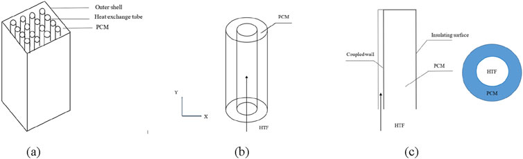
Figure 1. Physical models of phase change energy storage devices, concentric casing heat storage devices, and simplified horizontal and vertical physical models.
2.1.2 Numerical strategies and boundary condition
The problem of phase change heat transfer is also known as the “Stefan problem” (Patanka, 1984). The process of phase change heat transfer is often composed of three physical processes: heat conduction, convection heat transfer and phase change, which is more complex and difficult to solve than a single heat transfer process. Due to the nonlinear change law of the phase transition interface with time, the solution process becomes extremely difficult with many uncertain factors such as the release and absorption of latent heat on the phase transition interface, the properties of the phase change material, the interaction between the volume change and the container. The enthalpy mathematical model can solve this problem well, taking the enthalpy and temperature of the phase change material together as the variables to be solved, so as to establish a unified governing equation for the mixed paste region of both in the solid phase region, the liquid phase region or the liquid and solid phase interface, avoiding the problem that the parameter changes on the two are not only calculated by a simple linear combination method. The idea is approximately simplified to solve a single phase problem. After calculating the enthalpy distribution by numerical method, the temperature values at each node are solved according to the obtained information relationship. Due to the need to use the enthalpy-porosity solution in the melting/solidification module of Fluent software, the liquid phase rate is introduced to describe the movement rule of the two-phase interface indirectly. The source terms in the x and y directions should be added to the momentum conservation equation to obtain the pressure drop in the presence of a solid phase. Therefore, The calculation formula for the phase change process is as Equations 1–15, the governing equation of the phase transition process (Zhang, 2011) is treated as follows:
(1) Mass conservation equation (continuity equation):
(2) Momentum conservation equation:
(3) Energy conservation equation:
Where u and v are the components of the velocity in the x direction and the y direction; ρ is the density; μ is the dynamic viscosity; λ is the thermal conductivity; cp is the specific heat capacity; p is the pressure; Mx, My are the source terms of momentum in the x and y directions respectively; Sh indicates the energy source item.
The equation for enthalpy is:
Momentum equation source term and energy equation source term are:
Where, h is sensible heat; L is the latent heat of phase transformation; Tref is the reference temperature; href is the enthalpy corresponding to the phase change material at the reference temperature; β is the liquid phase fraction; ε is a constant less than 0.001, avoiding a denominator of 0; Amush is the paste region constant, usually 105; ρref is the density at reference temperature; g is the gravitational acceleration; α is the coefficient of volume expansion.
The liquid phase percentage is calculated by the formula:
Where, Tl refers to the liquid phase temperature of the material; Ts refers to the solid phase temperature of the material.
2.2 Phase change process simulation
The grid dimensions directly impact the simulation result accuracy. Thus, the calculation accuracy time needs to be considered, and the time step should be set to 0.1 s according to the same standard. The grid numbers were 6160, 7200, 8400, and 8680 respectively, and two coordinate points were set for observation. The results were shown in Table 1 when the heat storage time was the same. The physical parameters of paraffin phase change materials is shown in Table 2.
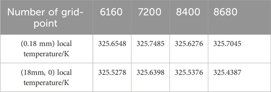
Table 1. The number of grids corresponds to the temperature of the observation point.
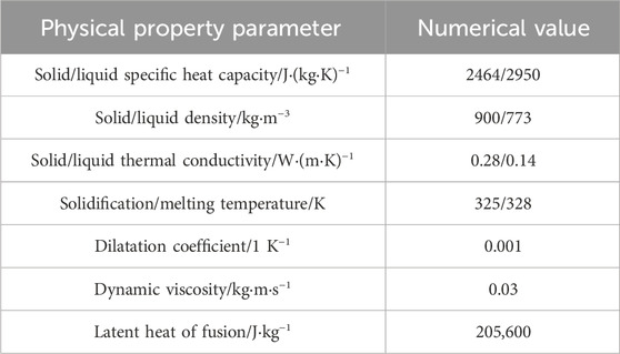
Table 2. Physical parameters of paraffin phase change materials.
The solution of the governing equations is founded upon the Finite Volume Method (FVM) implemented in Fluent. For pressure-velocity coupling, the SIMPLE algorithm is utilized, while the PRESTO scheme is applied for the pressure correction equation. The discretization of both the momentum and energy equations is carried out using the second-order upwind scheme. The under-relaxation factors for pressure, density, momentum, liquid fraction, and energy are designated as 0.3, 1, 0.7, 0.9, and 1, respectively. The convergence criteria for the continuity, momentum, and energy equations are set to 10−3, 10−5, and 10−8 in sequential order.
By comparing that the observation point is in the mushy region of the two-phase interface and the temperature deviation is within the expectation, a heat storage unit with 8400 grids is selected for simulation. In addition, using a structured grid, which is equivalent to a uniform grid within a rectangular domain in terms of topology, is therefore very effective for regularly shaped regions. The grid division is shown in Figure 2.

Figure 2. Meshing of concentric casings.
2.3 Simulation results and analysis
2.3.1 Melting and heat storage process of paraffin in concentric casing
The experimental results in this chapter are based on the horizontally placed heat storage device model of a heat storage unit with an outer tube diameter of 45 mm, an inner tube diameter of 15 mm, an initial temperature of 293 K (the initial temperature of the melting process is basically set at 293 K after referring to relevant materials), a heating source temperature of 350 K, and 8400 mesh elements. The phase change heat transfer process of paraffin phase change material in a concentric sleeve heat storage device under the condition of constant wall temperature is simulated. In actual working conditions, natural convection will inevitably occur and will inevitably have an impact on the heat transfer characteristics of the whole melting process and the movement law of the two-phase interface. Therefore, the prerequisite is under the condition of natural convection, that is, the Boussinesq assumption is selected for the density term, and there is a gravitational acceleration g along the y-axis, pointing in the negative direction of the y-axis. Through the post-processing, The temperature contour plots and melt fraction contours of paraffin at different times are shown in Figure 3.
Figure 3. The temperature contour plots and melt fraction contours of paraffin at t = 300 s (A), 600 s (B), 900 s (C), 1,200 s (D) and 1,500 s (E).
Among them, the blue area represents the solid phase region, the red area represents the liquid phase region, and the yellow-green mixed area simulates the paste region of the two-phase interface. It can be observed from the figures that when the melting time is from the initial moment to around t = 300 s, most of the paraffin phase change material in the whole heat storage device is still in the solid phase, and the temperature distribution is the same as the melting trend. Only a small part of the paraffin around the inner tube starts to melt into a liquid state. It can be observed that the melting speeds of the materials surrounding the inner tube are not the same. The phase change interface expands outward in a left-right symmetric but extremely up-down asymmetric trend. Moreover, the paraffin material above the inner tube has a high temperature and the fastest melting rate. Subsequently, it presents a non-linear development trend towards both sides, with the temperature gradually decreasing and thus the melting rate also becoming slower. The melting rate of the material below is extremely slow as a whole, and there is even no sign of melting at the beginning. The whole melting process lasts for a long time. As the time continuously increases from t = 300 s–1,500 s, the proportion of the liquid phase region also gradually increases. However, during the whole growth and change process, the temperature range, shape distribution, and phase change interface of the melting process always maintain a left-right symmetric but extremely up-down asymmetric development trend, just like a horizontally placed bowl-shaped figure. When the time increases to t = 1,500 s, the melting above has completely ended, the melting rate of the paraffin below is still extremely slow, and the phase change interface has approximately become a horizontal straight line.
The change curve of the liquid phase rate of the paraffin phase change material in the concentric tube over time is shown in Figure 4. According to the figure, the melting process can be divided into four stages: 1) In the initial stage, due to the large temperature difference between the paraffin and the heat source, the melting speed is rapid. 2) After 300 s, the melting speed slows down and then rises again. This is caused by the low liquid phase rate, the lack of strong natural convection, and the decreasing temperature difference between the paraffin and the heat source. 3) As the liquid phase rate increases, natural convection gradually becomes the dominant heat transfer mode. Despite the increase in thermal resistance, the strong natural convection makes the total thermal resistance decrease, resulting in a faster melting speed. 4) In the later stage, since the solid phase paraffin below is not affected by buoyancy, its main heat transfer mode is heat conduction. As the distance from the heating source increases, the thermal resistance increases, the heat transfer process weakens, and the phase rate curve tends to be flat. The simulation results are consistent with the literature (Zuo et al., 2005), indicating that the modeling and calculation are relatively scientific (Li et al., 2012).
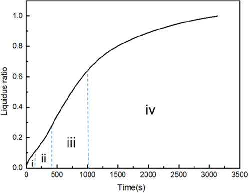
Figure 4. Liquid phase rate of concentric casing over time.
2.3.2 Heat release process of paraffin solidifying in concentric casing
With other parameters unchanged, the solidification process of paraffin was simulated at the initial temperature of 350K and the cold source temperature of 293K. The melt fraction contours of paraffin at different times are shown in Figure 5. The results show that there are two major differences from the melting process: 1) Although the phase change interface in the solidification process still starts to solidify in the trend of left-right symmetry and up-down asymmetry, the solidification rate of paraffin under the circular tube is slightly faster than that on the top; 2) n general, the phase transition interface basically forms a circular surface and steadily solidifies and expands outward.
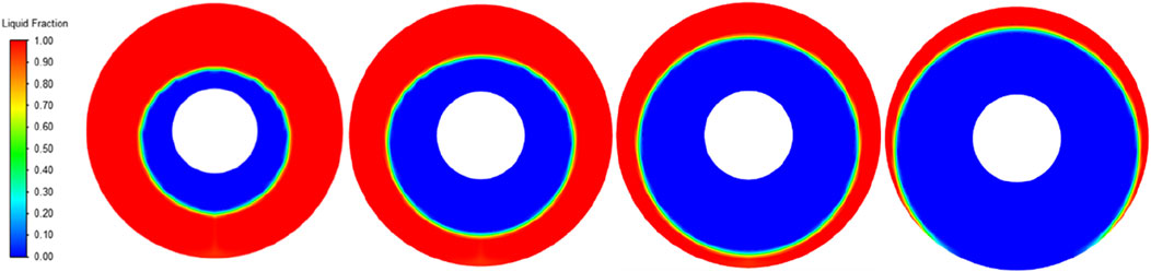
Figure 5. The melt fraction contours of paraffin at 600 s, 1,200 s, 1,800 s, and 2,400 s.
2.3.3 Influence of heat source temperature on the melting heat storage process
With other parameters unchanged and variable heat source temperature changed, the melting process of paraffin wax was simulated at initial temperature of 293K and heat source temperature of 330K, 340K, 350K, and 360K. The liquid phase rate change curve was shown in Figure 6A. The horizontal axis represents the heat source temperature, and the vertical axis represents the melting time. The results show that the liquid rate of paraffin melting process at different heat source temperatures has the same trend with time, and the higher the heat source temperature, the steeper the liquid rate curve. The time required for complete melting is shown in Figure 6B. The horizontal axis represents time, and the vertical axis represents the liquidus radio. In a certain temperature range, the increase of heat source temperature affects and reduces the complete melting time of paraffin. However, when a certain critical temperature is exceeded, the strengthening of the melting process by increasing the heat source temperature gradually weakens, which is consistent with the literature (Zheng and Wang, 2019).
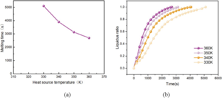
Figure 6. Different heat source temperatures correspond to the paraffin liquid phase rate with time curve and complete melting time.
Further analyze its heat transfer process and efficiency. It can be seen that the changing trend of the liquid fraction with time in the paraffin melting process phase change material at different wall temperatures is roughly the same: When the melting time reaches about 300 s, the rapid melting caused by the large initial temperature difference slows down due to the small liquid fraction, the not intense natural convection and the decreasing temperature difference. After passing through this slowly rising interval, the liquid fraction rises rapidly, the strong natural convection gradually begins to replace heat conduction, and acts together with heat conduction, and the heat transfer quantity increases rapidly. Until finally, about 20% of the paraffin melting takes about 60% of the total time. Since the solid paraffin below is not affected by the buoyancy force, is getting farther and farther away from the heating source, the thermal resistance of heat conduction increases, the heat transfer is weakened, and the melting rate slows down. The quantitative analysis is consistent with the previous conclusions and cause analysis; and the reason why the liquid fraction curve is steeper when the wall temperature is higher is that the increase in the temperature difference accelerates the progress of the above process, resulting in an overall increase in the melting speed.
2.3.4 Influence of cold source temperature on the solidification heat release process
With other parameters unchanged and variable cold source temperature changed, the solidification process of paraffin wax was simulated at initial temperature of 350K and cold source temperature of 283K, 293K, 303K, and 313K. The liquid phase rate change curve was shown in Figure 7A. The horizontal axis represents time, and the vertical axis represents the liquidus radio. The results show that the liquid phase rate of paraffin solidifying process at different cold source temperatures has the same trend with time. The lower the cold source temperature is, the steeper the liquid phase rate curve is. As shown in Figure 7B, the horizontal axis represents the cold source temperature, and the vertical axis represents the solidification time. The higher the cold source temperature, the longer the time required for complete solidification of liquid paraffin wax, and the increasing trend is more significant. Therefore, changing the cold source temperature in the high wall temperature segment is more effective in shortening the solidification time.
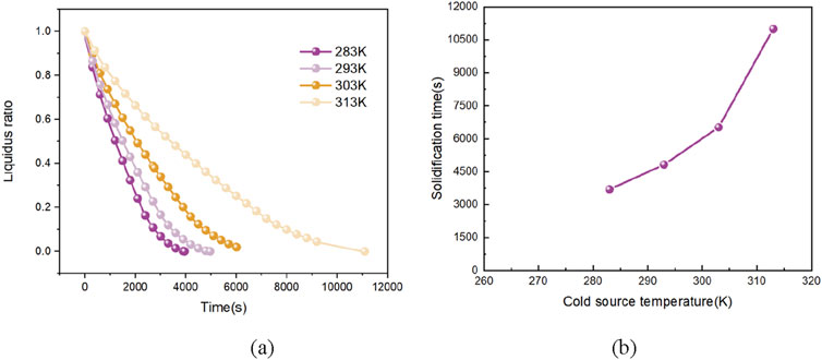
Figure 7. Different cold source temperatures correspond to the variation curve of paraffin liquid phase rate with time and the complete solidification time.
Further analyze its heat transfer process and efficiency. Different from the more effective measure of increasing the heat source temperature in the lower wall temperature interval to accelerate the heat efficiency of the heat transfer process in the melting process, the complete solidification time of paraffin changes more drastically in the higher wall temperature interval. Therefore, changing the wall temperature with a certain higher cooling wall surface will be more conducive to shortening the heat transfer time of the whole solidification process more quickly and achieving a more significant effect. And in the same temperature interval, the time required for the complete solidification of the paraffin phase change material is generally higher than that required for complete melting, which reflects from the side that the decrease in the liquid fraction makes the heat conduction of the solid paraffin gradually become the dominant heat transfer mode, and the role of natural convection in the solidification process is relatively minor compared with that in the melting process.
3 Simulation of heat storage phase change in eccentric casing
3.1 Model construction and phase transformation process simulation
It can be seen from Figure 3 that the thermal efficiency is not ideal due to the asymmetric melting trend of the paraffin phase transformation process in the concentric sleeve heat storage device caused by natural convection. In particular, the melting time of the paraffin wax at the bottom is greatly increased due to deviation from the natural convection area. The eccentric casing can make the heating source and melting area move down as a whole (Ji and Liu, 2022), and the melting of the lower part is much earlier than that of the concentric casing, and the melting of paraffin in both the upper and lower part can develop rapidly, thus improving the thermal efficiency (Ouyang, 2009).The cross section of eccentric casing is shown in Figure 8.
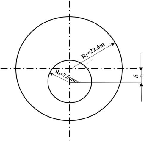
Figure 8. Example of cross-section of an eccentric casing heat transfer device.
3.2 Simulation results and analysis
The eccentricity of the variable was changed, and other parameters were set the same. The melt fraction contours of paraffin with eccentricity of 2 mm, 4 mm, 6 mm, 8 mm, 10 mm, and 12 mm were taken, as shown in Figure 9. The results show that the melting under the inner copper tube is obviously enhanced by increasing the eccentricity at 300 s. Between 300 s and 1,200 s, the eccentricity is increased so that the melting trend of the upper part of the inner copper pipe is similar, while the melting section of the lower part gradually extends to the wall of the outer pipe. When the time reached 1,200 s, the increase of eccentricity made the melting zone of the upper and lower paraffin develop rapidly. Compared with the advantage of the slightly leading melting speed in the early melting stage, the proportion of liquid paraffin increased rapidly at this stage. Finally, when the melting process comes to an end, the overall melting speed begins to slow down gradually, but the eccentric casing with large eccentricity is still ahead.
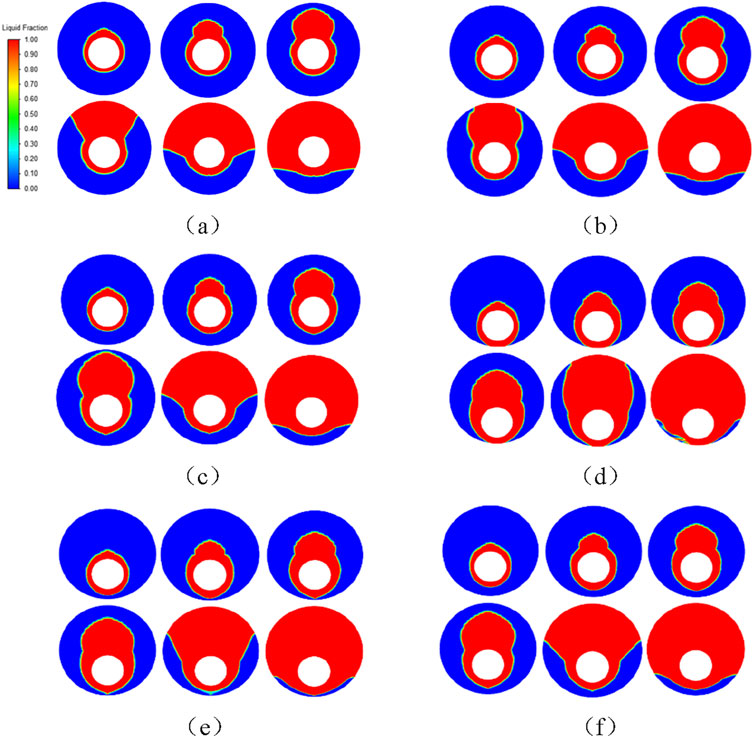
Figure 9. The melt fraction contours of paraffin in eccentric casing with eccentricity of 2 mm (A), 4 mm (B), 6 mm (C), 10 mm (D), 12 mm (E), and 14 mm (F) at 300 s, 600 s, 900 s, 1,200 s, 1,800 s, and 2,400 s.
The velocity vector distributions of the liquid-phase paraffin in the eccentric sleeve heat transfer devices with eccentric distances of 2 mm, 4 mm, 6 mm, 8 mm, 10 mm, and 12 mm at the moments of 300 s, 600 s, 900 s, 1,200 s, 1,800 s, and 2,400 s are shown in Figure 10 respectively. At the initial stage of melting when t = 300 s, in the sleeves with larger eccentric distances, the paraffin beneath the copper pipe inside the sleeve begins to show a downward extending and expanding trend of melting. The paraffin beneath, which would not have melted first under normal circumstances, changes the order of melting and is melted into the liquid phase together with the solid-phase paraffin above from the initial moment, resulting in natural convection in the liquid phase area. However, since the melting has just begun and the liquid fraction is small, the natural convection both above and below is not intense.
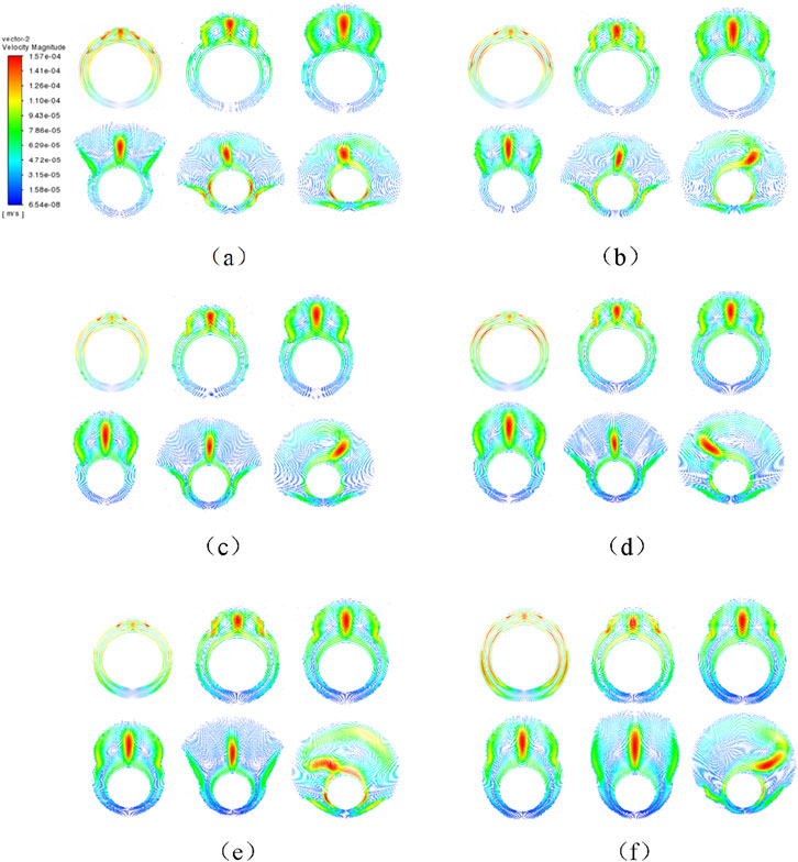
Figure 10. Velocity distribution vector diagrams of liquid-phase paraffin wax in eccentric casing with eccentricity of 2 mm (A), 4 mm (B), 6 mm (C), 10 mm (D), 12 mm (E), and 14 mm (F) at 300 s, 600 s, 900 s, 1,200 s, 1,800 s, and 2,400 s.
With the progress of the melting process, the sleeves with smaller eccentric distances follow the melting pattern of the concentric sleeves. The upward buoyancy force caused by the density difference pushes the liquid-phase paraffin, and the impact of the heat flow makes the melting area above expand rapidly, with a relatively large melting velocity vector. Meanwhile, the paraffin beneath is not affected. However, as the eccentric distance increases, while the melting trend above the inner copper pipe remains similar, the overall heating source and melting area move downward slowly and expand to the outer pipe wall. The proportion of the paraffin beneath the inner copper pipe drops sharply, and the thermal resistance of heat conduction of the solid-phase paraffin increases due to the increased distance from the heating source, which accelerates the melting speed. At the same time, the melted liquid-phase paraffin in contact with the outer pipe wall surface generates natural convective circular flow, and the velocity vector distribution in the liquid-phase area cannot be ignored, laying the foundation for the further development of melting. When the melting time reaches 1,200 s, the circular flow area caused by natural convection further expands with the increase of the liquid fraction. The advantage that the increase of the eccentricity can promote the further development of the natural convection both above and below becomes more obvious, and the heat transfer efficiency rises. Finally, when the melting process is nearing the end, the sleeve heat transfer devices with larger eccentricities, which have developed more rapidly and are filled with more widely distributed natural convective circular flows, complete the melting process first, and their overall melting speed is faster than that of the sleeve heat transfer devices with smaller eccentricities under the same conditions.
The variation curve of the liquid phase rate of paraffin is shown in Figure 11A. The horizontal axis represents time, and the vertical axis represents the liquidus radio. Before 1,200 s, the curve fit was close to almost coincidence, the large eccentricity caused the heating source and melting region to move down as a whole, and the natural convection generated by contact with the outer tube wall accelerated the melting speed, but the liquid phase rate was still low and could not produce strong natural convection. After 1,200 s, the increase of eccentricity increases the circulation flow interval caused by natural convection up and down, and the heat conduction of the lower solid phase paraffin is less due to the lower solid phase paraffin itself, the blocked liquid is less and the thermal resistance is smaller and the melting speed is accelerated, and the melting of the upper and lower are rapid development. The time required for each to completely melt is shown in Figure 11B. The horizontal axis represents the eccentricity, and the vertical axis represents the melting time. Increasing the eccentricity in a certain range is conducive to accelerating the melting process; However, the melting time decreases with the increase of eccentricity, and the influence of eccentricity on heat transfer is weakened.
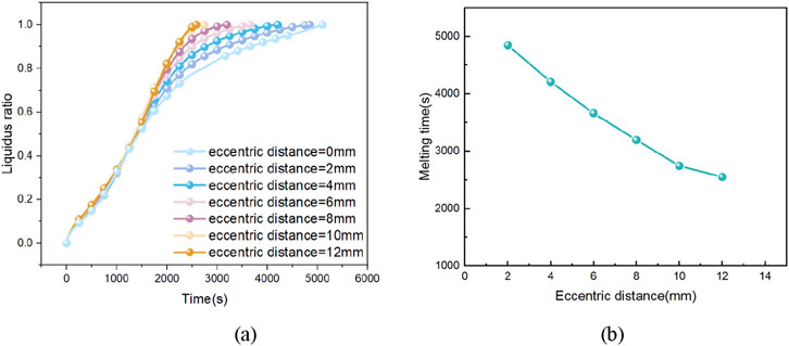
Figure 11. Liquid phase rate of paraffin wax in eccentric casing with different eccentricity and time of complete melting time.
Further analyze its heat transfer process and efficiency. The overall changing trend of the six curves is basically the same, and it is also extremely similar to the changing trend of the liquid fraction in the concentric double-pipe heat storage device. Before the melting time reaches 1,200 s, the six curves are closely attached and almost coincide. However, the overall downward movement of the heating source and the melting area caused by the larger eccentricity, and the natural convection generated due to the contact of the outer pipe wall accelerate the melting speed. But at this time, the value of the liquid fraction is still low and a strong natural convection has not been generated. So in this stage, the increase in the eccentricity only slightly accelerates the melting speed, and it is not obvious in the overall liquid fraction curve. When the melting time is greater than 1,200 s, it can be clearly found that with the increase in the eccentricity, the range of the cyclic flow caused by the natural convection above and below the inner copper pipe increases, playing a decisive role in the whole heat transfer process. And the heat conduction of the solid paraffin below is also because the amount of the solid paraffin in the lower part itself is small, the liquid blocked is less, so the thermal resistance is small and the heat transfer quantity is large. The natural convection and heat conduction act together, showing from all aspects that the increase in the eccentricity will accelerate the melting process of the un-melted solid paraffin and improve the overall heat transfer efficiency. Until the end of the melting process, the eccentric double-pipe device with a smaller eccentricity still follows the characteristics of the concentric double-pipe: The last 20% of the solid paraffin takes a lot of time to melt. And the increase in the eccentricity accelerates this slow melting process, and the larger the eccentricity, the more obvious this advantage is.
To further explore the impact of the eccentricity on the heat transfer characteristics of paraffin during the melting process in the casing, the time-average heat transfer coefficient during the melting process is calculated. The calculation formula is as follows:
According to Newton’s law of cooling, the convective heat transfer coefficient can be expressed as:
In the formula,
Combined with the above formula, in order to study the heat transfer performance during the phase change heat transfer process, the time-based average heat transfer coefficient is defined as follows:
In the formula,
After substitution, the comparison of the average heat transfer coefficients of paraffin in the concentric casing and the eccentric casing during the melting process and the differences in the average heat transfer coefficients of paraffin under different eccentricities during the melting process are obtained, as shown in Figure 12. It can be seen that the variation law of the average heat transfer coefficient during the melting process is consistent: it is the largest in the initial stage and decreases rapidly within a very short time. At this time, only a small amount of PCM near the heating surface melts, and the phase interface is distributed in a circular ring. In the second stage, the average heat transfer coefficient fluctuates within a small range for a relatively long period of time and basically remains stable until the PCM in the upper part of the container is completely melted. In the third stage, the heat transfer coefficient decreases rapidly to a very low value and then decreases slowly. In this stage, only a small amount of PCM in the lower part of the container remains in a solid state. Combining the results of the previous analysis, this variation law also conforms to the transformation of the heat transfer mechanism during the melting process. The average heat transfer coefficient of the eccentric container is higher than that of the concentric container. The larger the eccentricity, the more obvious the difference in the average heat transfer coefficient. The eccentric structure increases the PCM capacity above the heating surface, which is equivalent to expanding the region where natural convection occurs, thus prolonging the second stage of the melting process, that is, the stage where natural convection dominates heat transfer. The larger the eccentricity, the later the transition from the second stage to the third stage occurs.
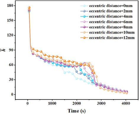
Figure 12. The changing trend of
4 Simulation of phase change heat storage process for finned enhanced heat transfer
4.1 Model construction and phase transformation process simulation
Through the simulation of phase change heat transfer process of paraffin wax in smooth casing, it is found that its thermal efficiency is not ideal, so strengthening the heat transfer and improving the heat transfer efficiency of phase change heat storage unit has become the primary problem. The addition of fins can increase the heat transfer area and improve the thermal efficiency. It should be particularly pointed out that the fins are not heat conducting. This section introduces fins to strengthen heat transfer and discusses its geometric parameters. The physical models and meshing of the casing model and the fin part are all presented in Figure 13. The physical model is a finned tube heat storage device with 4 straight ribs of equal section added to the outer wall of the copper pipe, as shown in Figure 13A. Each fin has a width of 2 mm and a height of 12.5 mm and is meshed, as shown in Figure 13B.
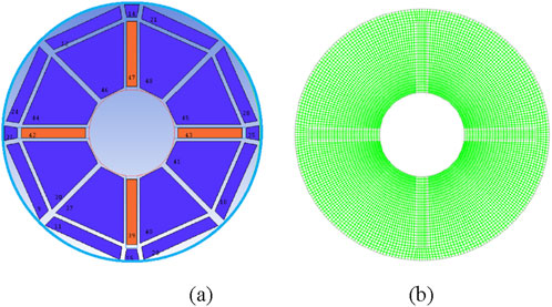
Figure 13. Physical model and meshing of finned tubes.
4.2 Simulation results and analysis
4.2.1 The process of melting and heat storage in finned tube is added
Other parameters are set to be the same. The temperature of the heat source is 350 K, and the initial temperature is 293 K. The melting and heat storage process of paraffin in the finned tube is simulated. The number of straight fins with equal cross-section of the increased extended surface is 4. Each fin has a width of 2 mm and a height of 12.5 mm, and the fin area is 100 square millimeters. The temperature contour plots and the distribution contours of paraffin phase transition interfaces at different times are shown in Figure 14. Place the temperature scale and the liquid fraction scale respectively on the left side of the contour map.
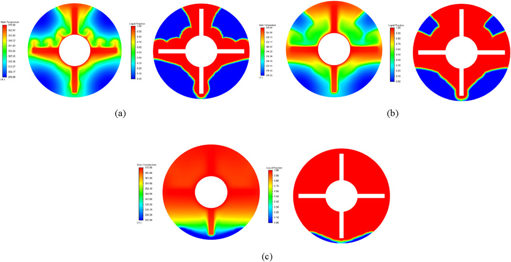
Figure 14. The temperature contour plots and melt fraction contours of paraffin at 300 s, 600 s, and 900 s.
It can be seen from the figure that before the melting starts, the heat transfer mode of the whole heat transfer process is the heat conduction of solid-phase paraffin. The paraffin begins to melt only when it reaches the phase change temperature. In the early stage of melting, when the time is from the initial moment to around t = 300 s, most of the paraffin phase change material in the whole heat storage device is still in the solid phase. The distribution range of liquid-phase paraffin is relatively narrow. The whole heat transfer path is still mainly based on the heat conduction in the solid-phase region. Visually, the solid-liquid two-phase interface seems to grow uniformly in all directions around the heat source and the rib wall surface except for the effect of natural convection above until there is an obvious change after the melting time gradually increases. As the time continuously increases within the range of t = 300 s–600 s, along with the continuous progress of the melting process, the increase in the proportion of the liquid-phase region is more intense compared with that of the bare tube. The natural convection in the liquid-phase region gradually becomes the main heat exchange mode of the whole heat transfer process and works together with heat conduction to transfer heat. Even though the heat conduction thermal resistance increases, the rapid increase in the proportion of the liquid-phase region makes the natural convection above very strong, and the melting range below is also larger than that of the bare tube heat storage device due to the extended surface, resulting in a decrease in the total thermal resistance and a high melting rate. When the time increases to t = 900 s, the melting of the phase change material above the fins has been completely finished, and the melting of the paraffin below the fins starts to move downward again from the previously melted small area around the fins. The phase change interface gradually becomes a curve that bypasses the fins. Similarly, the melting time of the last about one-third of the solid-phase phase change material accounts for more than half of the total melting time.
The change curve of liquid rate over time during the melting and heat storage process of paraffin wax in finned tube is shown in Figure 15. Compared with the curve of liquid rate change of paraffin wax in concentric casing, it can be seen that under the same working conditions, the change of liquid rate during the melting process of paraffin wax in finned tube is similar to that in casing, but the melting time of paraffin wax in casing is nearly three times that in finned tube. It can be seen that the addition of finned tubes is of great benefit to the improvement of thermal efficiency. Then the geometrical parameters of finned tubes are discussed.
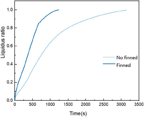
Figure 15. Variation curves of paraffin liquid phase rate with time in finned heat transfer device and plain tube heat transfer device.
Further analyze its heat transfer process and efficiency. The influence of natural convection on the heat transfer device with fins is still significant. During the whole heat storage process, just like the bare tube, starting from the initial moment t = 0 s, due to the large temperature difference between the paraffin and the heating source with fins and the expansion of the heat transfer area, the paraffin begins to melt rapidly, and the liquid fraction curve keeps rising. The paraffin close to the heating source including the fin area is first affected by the temperature of the heat source and begins to store heat, melts into the liquid phase, and generates a regional natural convection cyclic flow blocked by the fins upward. Subsequently, the slope of the liquid fraction curve slows down slightly for a short time less than 200 s due to the sparse distribution of liquid paraffin, the not intense natural convection, and the decreasing temperature difference between the paraffin and the heating source with fins and other factors. When the melting continues to the middle stage of melting around 300 s, at this time, the natural convection becomes stronger as the melting process progresses and the liquid fraction rises, becoming the mainstream heat transfer mode in the whole melting process, and acting together with heat conduction. The paraffin phase change material above the fins is continuously impacted by the heat flow, and the melting speed continues to increase with the increase in the liquid fraction. Visually, it is similar to the melting process of the bare tube under natural convection: The melting area above the fins is much larger than that below the fins, and it expands from the small melting area between the fins to the whole upper half area due to the blocking of the left and right fins, while the paraffin around the fins below expands slowly except for the small range of melting in the initial stage. Then, when it reaches the later stage of melting around t = 700 s, the paraffin below the copper tube begins to melt. Since the solid paraffin is not affected by the buoyancy force, is getting farther and farther away from the heating source, the thermal resistance increases, and the cyclic flow caused by natural convection makes the temperature of the whole liquid phase region uniform, the heat transfer temperature difference decreases, the temperature gradient becomes smaller, and the heat transfer process is weakened. The liquid fraction change curve of the finned tube heat storage device during the whole melting process is similar to that of the bare tube heat storage device, and the time is greatly shortened.
To further characterize the impact of adding fins on the heat - transfer process, the average Nusselt number Nu within the time interval of
Among them,
Among them,
After substitution, the comparison of the average Nusselt numbers of paraffin in the concentric smooth casing and the concentric finned casing during the melting process is obtained, as shown in Figure 16. It can be seen that for the two working conditions,
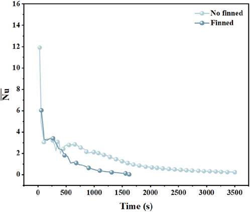
Figure 16. The changing trend of
4.2.2 Effect of fin height on melting and heat storage process of paraffin
Other parameters are set unchanged, take the height of the straight fin with equal cross-section as a variable. Select different heights of straight fins with equal cross-section, namely, 8.5 mm, 10.5 mm, 14.5 mm, and 14.5 mm respectively the fin areas are 68, 84, 100, and 116 mm2. Simulate the melting process of paraffin at the initial temperature of 293K and the heat source temperature of 350K. Figure 17 shows the melt fraction contours of paraffin in the thermal storage device with fin height of 8.5 mm and 12.5 mm at 300 s, 600 s, and 900 s. It can be seen that the presence of the fins has the effects of blocking, dividing and guiding the natural convection. Compared with the bare tube heat storage device, the natural convection generated above the inner copper tube is divided into two parts by the upper fins for regular flow respectively, and at the same time, the fins at the left and right ends force the two ends where there was originally no strong natural convection to extend to both sides, and are divided again into completely different flow situations above and below with the fins at both ends as the new dividing lines. Therefore, the addition of fins not only improves the thermal efficiency from the perspective of increasing the heat transfer area, but also improves the uneven distribution situation where the upper part of the original bare tube melts first and then the lower part melts slowly as if being divided. Overall, the problem of the excessive difference in the heat transfer speed above and below the inner copper tube is effectively alleviated, which has a positive impact on the entire heat transfer process.
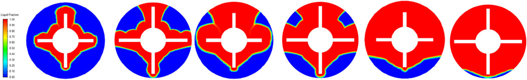
Figure 17. The melt fraction contours of paraffin in the thermal storage device with a fin height of 8.5 mm and 12.5 mm at t = 300 s, 600 s, and 900 s.
The liquid phase rate change curve is shown in Figure 18A. The horizontal axis represents fin height, and the vertical axis represents the melting time. It can be seen from the figure that the four curves are roughly in the same direction, and the heat transfer efficiency is improved compared with that of the casing. The higher the fin is, the higher the slope of the liquid phase rate curve is and the tighter it is. The time required for complete melting under different fin heights is shown in Figure 18B. The horizontal axis represents time, and the vertical axis represents the liquidus radio. The results show that the melting time gradually slows down with the decreasing trend of fin height, and the increase of fin height in the relatively small range has a significant effect on the improvement of thermal efficiency.
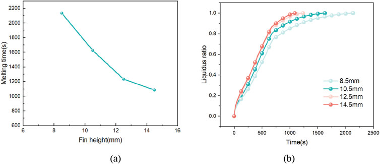
Figure 18. Liquid phase rate of paraffin wax in finned tubes with different fin heights as a function of time and complete melting time.
Further analyze its heat transfer process and efficiency. The general trend of the four curves is the same. The finned tube heat storage device generally saves more than three times the melting time of paraffin in the bare tube heat storage device, and the heat transfer efficiency is greatly improved. And the higher the fin, the larger the contact area between the heating surface and the hot fluid, the larger the slope of the liquid fraction curve and the closer it is, and the less time is required for complete melting.
4.2.3 Effect of fin width on melting and heat storage process of paraffin
Other parameters were set unchanged, take the thickness of the straight fin with equal cross-section as a new variable, and select the straight fins with equal cross-section whose widths are 2 mm, 4 mm, 6 mm, and 8 mm respectively, the fin areas are 100, 200, 300, and 400 mm2. Simulate the melting process of paraffin at the initial temperature of 293K and the heat source temperature of 350K. The melt fraction contours of paraffin in the thermal storage device with the fin widths of 2 mm and 6 mm at 300 s, 600 s, and 900 s was shown in Figure 19.
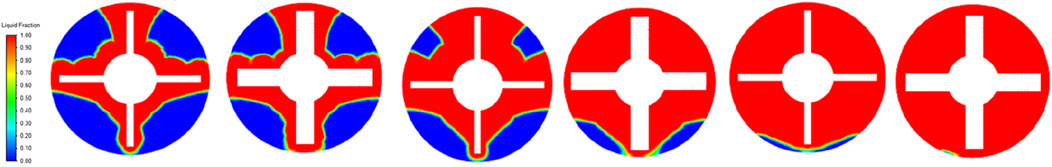
Figure 19. The melt fraction contours of paraffin in the thermal storage device with fin widths of 2 mm and 6 mm at t = 300 s, 600 s, and 900 s.
An increase in fin width, like an increase in fin height, will also block and inhibit the cyclic flow generated by natural convection, narrowing the range of cyclic activities and weakening the overall heat transfer efficiency to some extent. However, the extremely asymmetrical distribution characteristic of the melting speed caused by natural convection differentiates the impacts of an increase in fin width and an increase in fin height on natural convection: the natural convection below will find it difficult to expand the range of cyclic flow upwards due to an increase in the fin height on both sides, resulting in a significant decrease in heat transfer efficiency. In contrast, an increase in fin width will not interfere with the circulation between the upper and lower cycles, and the natural convection above and below with extremely asymmetrical melting speeds will still circulate cooperatively. Therefore, the overall heat transfer efficiency is only slightly weakened due to the narrowing of the range of cyclic flow.
The liquid phase rate change curve is shown in Figure 20A. The horizontal axis represents fin width, and the vertical axis represents the melting time. It can be seen from the figure that the four curves are roughly in the same direction, and the heat transfer efficiency is improved compared with that of the casing. And the distribution is more uniform in the simulation interval. The time required for complete melting under different fin widths is shown in Figure 20B. The horizontal axis represents time, and the vertical axis represents the liquidus radio. The melting time has a sharp downward trend with the increase of fin width, and no obvious slowing trend has been observed in the entire curve within the observed interval. Increasing fin width is an effective measure to strengthen heat transfer.
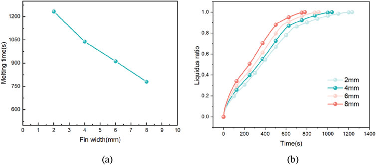
Figure 20. Liquid phase rate of paraffin wax in finned tubes with different fin widths as a function of time and complete melting time.
Further analyze its heat transfer process and efficiency. From a horizontal comparison, the general trend of the four paraffin liquid fraction curves corresponding to different fin widths is the same. The changing trend of the liquid fraction with time in each stage corresponding to each fin width is relatively the same as the influence brought by increasing the fin height on the heat transfer process of the whole heat storage device. But at the same time, from a vertical perspective, although the gradual increase in the fin width has a blocking and suppressing effect on the cyclic flow generated by natural convection, it only narrows the small range of the cyclic flow due to the increase in the fin width and does not have a too great impact on the overall changing trend of the paraffin liquid fraction, and the acceleration of the paraffin melting is still very obvious.
5 Conclusion
Numerical models of paraffin phase change materials with conventional tube type, eccentric tube type and fin enhanced heat transfer type were established by CFD simulation software. The heat absorption and release characteristics and liquid phase rate changes of paraffin phase change materials under the above three conditions were simulated and analyzed, and the heat transfer characteristics were analyzed combined with velocity vector diagram. The main conclusions are as follows:
(1) The melting process of paraffin in concentric casing can be divided into four stages, and the melting process expands with the trend of left-right symmetry and up-down asymmetry. Although the phase change interface in the solidification process still began to solidify in the trend of left and right symmetry and upper and lower asymmetry, the solidification speed of paraffin wax under the circular tube was slightly faster than that on the top.
(2) In the melting process, the higher the temperature of the heat source, the time required for the complete melting of the solid phase paraffin is shorter, but the shortening trend becomes slower with the increase of temperature. During the solidification process, the higher the cold source temperature, the longer the time required for complete solidification of liquid phase paraffin, and the increasing trend gradually increases with the increase of temperature.
(3) Augmenting the eccentricity within the eccentricity range of less than 0.67 is conducive to expediting the melting process. However, once this threshold is surpassed, the impact of eccentricity on the heat transfer process attenuates.
(4) The addition of fins expands the circulation flow area, and the left and right fins interfere with the upward expansion of the paraffin below, driving a wider range of circulation flow. Under the same working condition, the melting time of concentric casing is nearly three times that of finned tube. Increasing fin height in a relatively small interval has a significant effect on the improvement of thermal efficiency. When the fin width is changed, the melting time decreases significantly with the fin width increasing in the set range. That is, increasing fin width is more effective than increasing fin height.
(5) In this study, the optimal range of eccentricity increment for accelerating the melting process, derived from the simulation model, was identified as an eccentricity value less than 10, approximately corresponding to an eccentricity ratio below 0.67. Future research will conduct a series of additional experiments and simulations to validate this finding. From the perspective of optimizing heat transfer and enhancing thermal efficiency during the melting process, it was found that an excessive increase in fin height leads to a significant reduction in the circulating flow region due to natural convection, resulting in a plateau or even a decline in heat transfer efficiency improvement. In contrast, increasing the fin width, considering the economic factors in the manufacturing process, is an effective way to enhance heat exchange. Future work will focus on increasing the number of experiments and simulations to accurately determine the optimal fin width ratio, providing more comprehensive and reliable insights for the development and optimization of related heat transfer systems.
(6) Do not simplify the geometric structure into a 2D domain in order to consider any end effects and axial flow convection caused by the rectangular layout of the equipment.
Data availability statement
The original contributions presented in the study are included in the article/supplementary material, further inquiries can be directed to the corresponding author.
Ethics statement
The studies involving humans were approved by the shanghai university of electric power. The studies were conducted in accordance with the local legislation and institutional requirements. Written informed consent for participation was not required from the participants or the participants’ legal guardians/next of kin because the article does not need an ethical explanation.
Author contributions
SY: Formal Analysis, Methodology, Software, Validation, Visualization, Writing–original draft, Writing–review and editing. ZL: Data curation, Formal Analysis, Investigation, Resources, Writing–review and editing. YY: Investigation, Resources, Writing–review and editing. TZ: Data curation, Methodology, Writing–original draft, Writing–review and editing. LQ: Investigation, Resources, Writing–review and editing.
Funding
The author(s) declare that no financial support was received for the research, authorship, and/or publication of this article.
Conflict of interest
The authors declare that the research was conducted in the absence of any commercial or financial relationships that could be construed as a potential conflict of interest.
Publisher’s note
All claims expressed in this article are solely those of the authors and do not necessarily represent those of their affiliated organizations, or those of the publisher, the editors and the reviewers. Any product that may be evaluated in this article, or claim that may be made by its manufacturer, is not guaranteed or endorsed by the publisher.
References
Abdulrahman, R. S., Ibrahim, F. A., Dakhil, S. F., Darzi, A., Farhadi, M., and Sedighi, K. (2019). Development of paraffin wax as phase change material based latent heat storage in heat exchanger. Appl. Therm. Eng. 150, 193–199. doi:10.1016/j.applthermaleng.2018.12.149
Chen, H., Li, H., Xu, Y., et al. (2024). Research progress of energy storage technology in China in 2023. Energy Storage Sci. Technol. 13 (05), 1359–1397. doi:10.19799/j.cnki.2095-4239.2024.0123
DarziA, R., Farhadi, M., Sedighi, K., et al. (2010). Numerical study of melting inside concentric andeccentric horizontal annulus. Appl. Math. Model. 36 (9), 4080–4086. doi:10.1016/j.apm.2011.11.033
Eslami, M., Khosravi, F., and Kohan, H. R. F. (2021). Effects of fin parameters on performance of latent heat thermal energy storage systems: a comprehensive review. Sustain. Energy Technol. Assessments 47, 101449. doi:10.1016/j.seta.2021.101449
Ji, W., and Liu, W. (2022). Numerical simulation of melting heat transfer in Paraffin Phase Change energy storage Device. Light Ind. Mach. 40 (2), 27–33. Available at: http://m.qikan.cqvip.com/Article/ArticleDetail?id=7106997310
Kumar, R., and Verma, P. (2020). An experimental and numerical study on effect of longitudinal finned tube eccentric configuration on melting behaviour of lauric acid in a horizontal tube-in-shell storage unit. J. Energy Storage 30, 101396. doi:10.1016/j.est.2020.101396
Li, W., Zhao, J., Li, X., et al. (2012). Numerical simulation of external phase variable heat storage process of a horizontal circular tube in a square groove. Therm. power Eng. 27 (2), 181–186.
Li, Y., Wang, C., Zong, J., et al. (2019). Comparative Analysis of different forms of phase change heat storage heat exchangers. Energy Storage Sci. Technol. 8 (2), 347–356.
Liu, G., Yi, W., Guan, J., et al. (2019). Optimization of the number of fins during the water freezing and melting process. J. Ordnance Equip. Eng. 40 (1), 226–230.
Ouyang, M. (2009). Numerical simulation of pin-fin tube phase change heat storage and heat transfer performance. China: Chongqing University.
Patanka (1984). Numerical calculation of heat transfer and fluid flow. Amercia: Beijing Science Press.
Tan, Z., Li, M., and Li, C. (2023). Study on the heat transfer characteristics of phase change cold storage gel in tube-fin cold storage devices. Energy Storage Sci. Technol. 12 (12), 3740–3748.
Wang, H., and Cheng, B. (2024). Optimization of Phase change heat Storage Air source Heat pump System and solar complementary heating system. Energy Storage Sci. Technol. 13 (06), 1980–1982.
Yuan, P., Sun, X., Hongxu, C., et al. (2018). Design of shell-and-tube heat storage devices and three-dimensional numerical simulation and optimization of heat storage units. Therm. Energy Storage Sci. Technol. 17 (2), 02–110.
Zhang, S. (2011) Computational fluid dynamics and its applications [M], 1. Wuhan: Huazhong University of Science and Technology Press.
Zhang, Y., Yun, H., Zhang, Y., et al. (2013). Numerical simulation of shell and tube phase change heat storage device. Refrig. Air Cond. 27 (4), 329–334.
Zheng, Y., and Wang, Z. (2019). Study on the heat transfer characteristics of a shell-and -tube phase change energy storage heat exchanger. Energy Procedia 158, 4402–4409. doi:10.1016/j.egypro.2019.01.777
Zheng, Z. J., Xu, Y., and Li, M. J. (2018). Eccentricity optimization of a horizontal shell-and-tube latent-heat thermal energy storage unit based on melting and melting-solidifying performance. Appl. Energy 220, 447–454. doi:10.1016/j.apenergy.2018.03.126
Zhu, X., Li, Y., and Zhu, Q. (2022). Heat transfer enhancement technology for fins in phase change energy storage. J. Energy Storage 55, 105833. doi:10.1016/j.est.2022.105833
Zou, Y. (2020). Simulation study on heat storage process of paraffin phase change materials. Energy Storage Sci. Technol. 9 (1), 2095–4239.
Keywords: phase change heat storage, paraffin wax, numerical simulation, eccentric distance, fin reinforced heat transfer
Citation: Yiting S, Liting Z, Yongwen Y, Tao Z and Qifen L (2025) Numerical investigation on structure optimization and heat transfer of a phase change accumulator based on changing eccentricity and fin parameters. Front. Therm. Eng. 5:1501448. doi: 10.3389/fther.2025.1501448
Received: 25 September 2024; Accepted: 08 January 2025;
Published: 30 January 2025.
Edited by:
Bidyut Baran Saha, Kyushu University, JapanReviewed by:
Elias Papanicolaou, National Centre of Scientific Research Demokritos, GreeceChandrmani Yadav, Sandip Institute of Technology and Research Centre, India
Copyright © 2025 Yiting, Liting, Yongwen, Tao and Qifen. This is an open-access article distributed under the terms of the Creative Commons Attribution License (CC BY). The use, distribution or reproduction in other forums is permitted, provided the original author(s) and the copyright owner(s) are credited and that the original publication in this journal is cited, in accordance with accepted academic practice. No use, distribution or reproduction is permitted which does not comply with these terms.
*Correspondence: Zhang Liting, MTI5NzI1NjgzMEBxcS5jb20=