 Seyed Soheil Mousavi Ajarostaghi
 Sébastien Poncet
94% of researchers rate our articles as excellent or good
Learn more about the work of our research integrity team to safeguard the quality of each article we publish.
Find out more
ORIGINAL RESEARCH article
Front. Therm. Eng. , 23 September 2022
Sec. Thermal Science and Energy Systems
Volume 2 - 2022 | https://doi.org/10.3389/fther.2022.961083
This article is part of the Research Topic Advancements in Heat and Mass Transfer for the Efficient Design of Thermal Systems View all 4 articles
The present paper investigates the thermal mixing and cooling processes in a passive micromixer, which is applicable for the cooling of electronic devices. Employing a porous block and testing different configurations for the mixing channel is considered to enhance the mixing process and cooling performance. A 2D lattice Boltzmann thermal model is utilized to investigate the thermal performance of a T-micromixer with a porous block. Two different types of mixing channel configurations, including a step-shaped and a zigzag-shaped channel, are considered, and the obtained results are compared with those of the simple mixing channel. The thermal mixing and cooling of two miscible fluids, at 50 and 25°C entering the micromixer, are investigated. The results show that changing the mixing channel configuration may create a chaotic laminar flow, which enhances the heat transfer rate between the mixed flow and the channel wall. Whatever the Reynolds number, the step-shaped mixing channel exhibits better mixing performance than the zigzag-shaped one. For the T-micromixer with a zigzag-shaped and step-shaped mixing channel, the cases with h/H = 0.5 and h/H = 0, respectively, exhibit better thermal mixing and cooling performance.
Many electromechanical systems have been progressively miniaturized, and their thermal management in small volumes is getting more and more challenging. As devices become smaller, heat flux generally rises. So, a practical cooling approach to microdevices is deemed necessary to prevent the formation of hot spots. Microfluidic heat exchangers are among the most promising devices cooling devices for electronics (Cho et al., 2010; Tullius et al., 2011; Mu et al., 2015). Multiple interesting microchannel configurations have been proposed over the last decades, and numerous studies are in process to gain a better understanding of the fluid flow characteristics in microchannels (Siddiqui and Zubair, 2017; Narendran et al., 2018).
Mixing plays a crucial role in different processes, especially in microfluidic systems (Myers et al., 1997; Fletcher et al., 2004; Wasewar and Sarathi, 2008). The simplest micromixer is a T-shaped one in which two streams are mixed in a simple straight channel. Some T- micromixers, which are static mixers, have some advantages over dynamic mixers: a short residence time and lower maintenance costs. Although numerous studies have been done to improve the performance of micromixers, detailed thermal mixing in a T-micromixer has yet to be examined more intensely. Most of the previous studies focused on either thermal mixing for macro-scale applications or on flow dynamics while omitting considering heat transfer in micromixers (Gobby et al., 2001; Wong et al., 2004).
Evrim and Laurien (Evrim and Laurien, 2021) considered thermal mixing in a T-shaped channel in both horizontal and vertical positions. Their numerical simulations have been done using the commercial CFD code, ANSYS ICEM. They evaluated the impact of the cold fluid flow on the proposed channel having different shapes. Their results showed that thermal mixing is enhanced when the channel is placed in a vertical position because of unstable thermal stratification. Feng et al. (Feng et al., 2019) investigated numerically the thermal mixing characteristics of a condensation process using a two-phase model available within the commercial CFD code, STARCCM+. Results demonstrated that the condensation rate was closely related to the coolant thermodynamic ratio between the primary and branch pipes (hot and cold streams). An empirical correlation was also provided to calculate the condensation rate. Su et al. (2020) evaluated numerically using ANSYS FLUENT 17.1 the thermal mixing in a T-shaped channel in the presence of inflow pulsation. Various temperature differences between the two inlet streams (hot and cold) were analyzed. Reverse flow happened in the proposed channel because of inertia, but it could be reduced by raising the temperature difference between the inlet streams, which caused more stable thermal stratification. Douroum et al. (2021) investigated the thermal mixing numerically in micromixers with various geometries, including TLCCM type (Two-Layer Crossing Channels Micromixer), L-Shape, OH-shape, and OX-shape. The Navier-Stokes equations were solved numerically using ANSYS FLUENT. It is worth mentioning that in all considered geometries, the equivalent length and hydraulic diameter were kept constant. The Reynolds number range studied was Re = [0.2–70]. Among the evaluated geometries of the micromixer, the TLCCM type demonstrated the best thermal mixing performance (by about 99% at Re = 20) with the lowest mixing energy cost in comparison with the other models.
Chuang and Ferng (2017) performed tests to evaluate the turbulent thermal mixing process in a T-shaped channel for various mass flow rates (both hot and cold streams) and inlet directions. They defined the velocity ratio Vr = Vb/Vm (Vb and Vm are the velocities in the branches and main pipe, respectively). Thermal mixing was found to depend significantly on this parameter, Vr. They defined a second dimensionless parameter, the momentum ratio MR = Mm/Mb (Mm and Mb are the momentum in the main pipe and the branches, respectively) to identify a possible reverse flow in the channel. For MR<0.05, the probability of backflow increases. Zhou et al. (Zhou et al., 2018; Zhou et al., 2019a) considered the fluid flow and thermal mixing in a T-shaped channel. The tests were performed for various inlet temperatures in the main pipe (including 240, 200, and 160°C), but the inlet temperature in the cold stream (branch pipe) was kept constant at 20°C. Raising the temperature difference between the hot and cold streams (branch and main streams) leads to the more stable thermal classification of the mixed flow. Also, it can be concluded that thermal fatigue depends heavily on the high-temperature fluctuations that could be created by the unstable stratified mixing flow. In another work, Zhou et al. (2019b) performed complementary experimental and numerical tests for a slightly different geometry: the cold stream in one branch enters the main channel at a variable angle. It induces tangential oscillations of the thermal stratification, which reduces the overall thermal fatigue of the main pipe. Selvam et al. (Selvam et al., 2017) investigated thermal mixing in a T-shaped channel for two temperature differences, ∆T = 65 and 143°C, experimentally and numerically. A moderate mixed stratified flow was observed for both temperature differences. ΔT = 143°C produced the most stable stratification due to buoyancy effects.
Using a porous zone is an efficient passive method in various industrial applications, including petroleum processing, heat exchangers (microporous and direct contact), drying processes, solar collectors, etc. Nevertheless, little attention has been paid to thermal mixing in complex systems like a T-shaped micromixer involving porous regions (Baragh et al., 2018; Baragh et al., 2019; Teggar et al., 2021; Mousavi Ajarostaghi et al., 2022).
In this work, a T-micromixer with a porous block located at the junction of two streams was considered, and thermal mixing and cooling processes were investigated by LBM. Here, the properties of the porous medium, including its porosity, position, aspect ratio, and effective thermal conductivity are kept constant. The objective of the present paper is to investigate the impact of the mixing channel configuration on the thermal mixing and cooling processes using the validated LBM solver. Two different types of mixing channel configurations, including step-shaped and zigzag-shaped, are considered, and the results are compared to the simple mixing channel.
A schematic view of the T-micromixer is shown in Figure 1 with its main dimensions. Two streams of the same fluid (kinematic viscosity ν) but at different temperatures are imposed at the two inlets of the microchannel: T1 = 50°C, T2 = 25°C with u1 = u2. Four values of the inlet Reynolds number Re = u1H/ν are considered in the following sections, namely Re = 25, 50, 75, and 100, where H = 20 µm is the width of all channels. The wall temperatures of the two branches, forming an angle α = 90° with the horizontal direction, are fixed to T1 and T2, respectively. After the thermal mixing of the two miscible streams, the cooling of the mixed flow is performed in the mixing channel, whose walls are at a constant temperature of T0 = 0°C. Thus, thermal mixing and cooling processes are investigated in the present case. The porous block of height w = 20 µm and length L = 20 µm is inserted at the inlet of the mixing channel. The coordinates of its center are y = H/2 (fixed) and x = h (variable). Outflow conditions (∂u/∂x = ∂v/∂x = 0) are imposed at the outlet of the mixing channel. Two geometries of the mixing channel are considered, namely a zigzag-shaped and a step-shaped mixing channel, and compared to the base case of a simple straight channel.
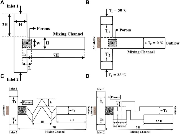
Figure 1. Schematic configuration of the T-micromixer with (A) relevant notations, (B) boundary conditions, (C) zigzag-shaped mixing channel, and (D) step-shaped mixing channel.
The fluid flow and heat transfer are solved on a Cartesian grid with the Lattice Boltzmann Method using the Bhatnagar–Gross–Krook (BGK) operator and a D2Q9 scheme. The collision and streaming steps proper to the LBM are performed, and the classical normalization is adopted so that the grid spacings and time step are set to ∆x = ∆y = 1 and ∆t = 1, respectively.
According to the kinetic theory, LBM uses Single-particle density distribution to simulate the fluid flow. The Lattice Boltzmann equation with external forces writes as (Balootaki et al., 2018; Toghaniyan et al., 2018; Afrouzi et al., 2019):
where the discrete equilibrium function is:
where τ is the relaxation time of the single relaxation time BGK model, which is related to the kinematic viscosity ν by
Besides the distribution functions for the hydrodynamic field f, a distribution function for the thermal field g is utilized for modeling the thermal process. The g distribution function is given by Eqs 3, 4 as proposed by (Balootaki et al., 2018; Toghaniyan et al., 2018; Afrouzi et al., 2019):
where τg is the single thermal relaxation time and:
The density, velocity, and temperature can be obtained by:
The Brinkman-Forchheimer equation is used to model laminar flows in a porous medium. It writes (Jourabian et al., 2018; Kazemi Moghadam et al., 2020):
where G is the gravity acceleration and υeff is the effective viscosity. In Eq. 8, the presented term in the parenthesis on the right-hand side is the body force (F). This term is achieved by utilizing Ergun’s relation.
The corresponding distribution functions for a porous medium are the same as in Eqs 1, 2. However, the equilibrium distribution functions and the forcing term write (Balootaki et al., 2018; Jourabian et al., 2018; Nemati et al., 2018):
The effective thermal conductivity is evaluated through (Balootaki et al., 2018; Jourabian et al., 2018; Nemati et al., 2018):
where
and the effective thermal conductivity ratio (named conductivity ratio hereafter for the sake of brevity) is defined as:
with ks the conductivity of the solid in the porous medium. The porosity and effective thermal conductivity ratio have been kept constant throughout this study and fixed to ε = 0.7 and σ = 0.0001, respectively.
The average Nusselt number and the transfer heat transfer coefficient, are calculated as follows (Guo and Zhao, 2002; Kazemi Moghadam et al., 2020; Kazemi Moghadam et al., 2021):
The domain has been discretized on a uniform Cartesian grid in both directions. Each cell holds a fixed number of distribution functions, representing the number of fluid particles moving in these discrete directions.
Regarding the flow field, the solid walls are assumed to be no-slip, and thus the bounce-back scheme is applied for all walls of the computational domain except at the inlets and outlet. For instance, for the flow field, the following conditions are used for the north and south boundaries of the mixing channel, respectively:
where n indicates the lattice on the boundary. Constant inlet velocity is considered for the inlets of the proposed micromixer which the velocity magnitude is calculated according to the Reynolds number. Outflow condition is considered for the outlet. For boundaries with a specified temperature, T = Tin, the unknown distribution functions are:
In this study, 2D thermal LBM was employed to evaluate numerically the thermal mixing and cooling processes in a T-micromixer with a porous block. The influence of the mixing channel configuration on the thermal mixing and cooling processes is investigated numerically. Two different configurations of the mixing channel, including a step-shaped and a zigzag-shaped channel, are considered for various h/H ratios (see Figure 1).
To validate the present thermal LBM solver as an efficient numerical method, the fluid flow in a channel with a porous zone is modeled for two different configurations, namely a fulfilled channel with a porous medium, considered analytically by Guo and Zhao (Guo and Zhao, 2002), and a partially filled channel with a porous medium, considered analytically by Alazmi and Vafai (Alazmi and Vafai, 2001). In the first validation case (Guo and Zhao, 2002), Re = 100, Pr = 0.7, ε = 0.1, and Da = 10−5, where Da is the Darcy number defined as Da = α/H2 (α and H are thermal diffusivity and the height of the channel filled with porous medium, respectively). In the second validation case (Alazmi and Vafai, 2001), Re = 1, Pr = 0.7, ε = 0.1, and Da = 10−3.
The validation results are illustrated in Figure 2 regarding the axial distribution of the normalized streamwise velocity. For the fully filled channel with a porous medium, an excellent agreement is obtained with a slight underestimation of the boundary layer thickness in Figure 2A. In Alazmi and Vafai’s (Alazmi and Vafai, 2001) case, the porous medium is located for y/H between 0 and 0.5, and a clear region is situated above. The present LBM perfectly matches the analytical solution, especially at the porous-fluid interface, which is usually challenging for numerical methods, as shown in Figure 2B.

Figure 2. Axial distributions of the normalized streamwise velocity: (A) Comparison with the analytical solution of Guo and Zhao (Guo and Zhao, 2002) for a fully filled channel with a porous medium; (B) Comparison with the analytical solution of Alazmi and Vafai (Alazmi and Vafai, 2001) for a partially filled channel with a porous medium.
The analytical results of Kays and Crawford (Kays and Crawford, 1993) were obtained for a parallel-plane duct in which the two surfaces are subject to a heat flux equal to
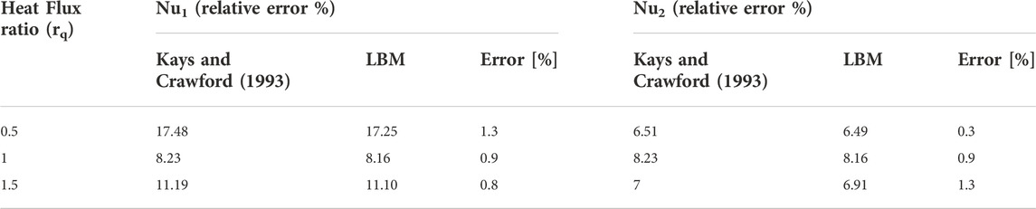
Table 1. Comparison in terms of the average Nusselt numbers between the present LBM and the analytical results of Kays and Crawford (Kays and Crawford, 1993).
All calculations have been performed using a uniform Cartesian grid composed of square elements. A grid independence study was done first for Re = 25, Pr = 0.7, ε = 0.7, σ = 0.0001, β = 90 degrees, h/H = 0, and w/L = 1, considering five different mesh grids, including; 160 × 100, 240 × 150, 320 × 200, 480 × 300, and 640 × 400 in the (x, y) plane. Figure 3 shows that the grids composed of 320 × 200, 480 × 300, and 640 × 400 elements provide very similar results regarding the temperature profile at the outlet and the velocity profile at x = 2H. The grid 320 × 200 offering the best compromise between accuracy and computational effort, has been selected for all numerical simulations.
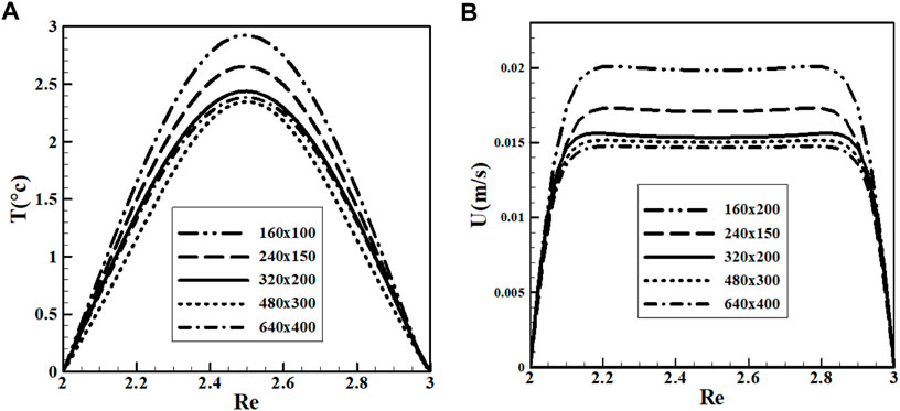
Figure 3. Results of the grid independency analysis for Re = 25, Pr = 0.7, ε = 0.7, σ = 0.0001, β = 90 degrees, h/H = 0, and w/L = 1: (A) temperature profile at the outlet and (B) streamwise velocity profile at x = 2H.
The present thermal LBM solver can now be used confidently to investigate the influence of the different proposed geometric parameters on the mixing and cooling performance of the T-shaped micromixer.
This section considers a T-shaped micromixer (β = 90°, where β is the angle between the two inlet streams.) with a step-shaped mixing channel and three different values of the h/H ratio, including 0, 0.25, and 0.5. Thermal mixing is investigated for Reynolds numbers ranging between 25 and 100. The schematic configuration of the T-micromixer with relevant notations, boundary conditions, and step-shaped mixing channel is shown in Figures 1A,B,D, respectively. The results presented below have been obtained for Pr = 0.7, σ = 0.0001, and ε = 0.7.
Figure 4A shows the vertical temperature profile at the channel outlet for Re = 25. This parameter is a good performance indicator to measure the micromixer's thermal mixing and cooling capacities. A lower maximum temperature value at the outlet indicates better cooling and thermal mixing processes. As a result, the cooling process is accelerated in the case with h/H = 0. Also, the results suggest that the step-shaped micromixer exhibits better thermal mixing than the simple mixing channel, whatever the value of the h/H ratio. The same trend is achieved in Figure 4B for Re = 50, but with higher temperature levels compared to that for Re = 25 (Figure 4A).
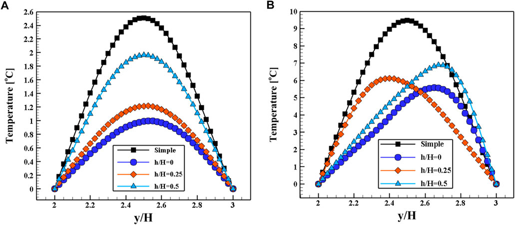
Figure 4. Vertical temperature profile at the outlet for (A) Re = 25, (B) Re = 50. Results were obtained for the T-shaped micromixer with a step-shaped mixing channel at Pr = 0.7, σ = 0.0001, and ε = 0.7.
To better realize the effect of the mixing channel geometry for the T-micromixer with a step-shaped mixing channel, the temperature contours are plotted in Figure 5, along with four values of the h/H ratio. Firstly, changing the shape of the mixing channel (simple to step-shaped) increases the mixing length, leading to a longer mixing time and, consequently, a better cooling process. Accordingly, the step-shaped mixing channel could be an efficient method to increase thermal mixing. However, as the ratio h/H increases, the size of the vortexes located in the corners of the channel rises, which leads to a lower heat transfer rate. In other words, more compact eddies in contact with an isothermal surface lead to a better heat transfer rate. So, the case with h/H = 0 shows a better overall cooling process and thermal mixing.
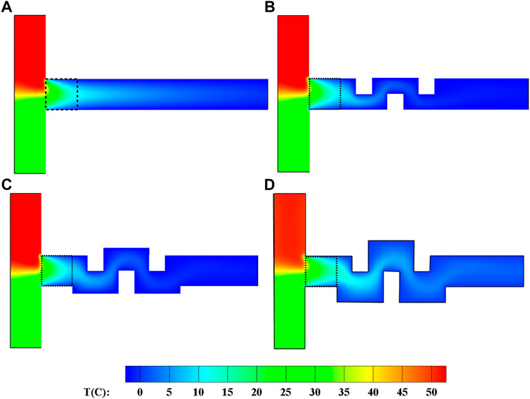
Figure 5. Temperature contours for the step-shaped mixing channel at Re = 25, σ = 0.0001, Pr = 0.7, and ε = 0.7: (A) simple, (B) h/H = 0, (C) h/H = 0.25, and (D) h/H = 0.5.
The average fluid temperature in the mixing channel and average fluid temperature at the outlet versus different Reynolds numbers for various models are illustrated in Figure 6. Generally, both figures exhibit the same trend, whatever the Reynolds number. The case with a simple mixing channel shows a higher temperature or, in other words, lower performance of thermal mixing. However, utilizing a step-shaped channel leads to higher mixing length, higher mixing time, and better thermal mixing. The temperature contours for various models in the step-shaped mixing channel at Re = 25, σ = 0.0001, and ε = 0.7 are shown in Figure 7. It can be seen that at the lowest value of h/H, h/H = 0, the velocity magnitude reaches a maximum. So, due to forced convection, the case with h/H = 0 exhibits a higher heat transfer rate or more thermal mixing.

Figure 6. (A) Averaged fluid temperature in the mixing channel (from x/H = 1–8), and (B) averaged fluid temperature at the outlet (x/H = 8) as a function of the Reynolds number. Comparisons between the simple and step-shaped channels for three values of h/H, at Pr = 0.7, ε = 0.7, and σ = 0.0001.
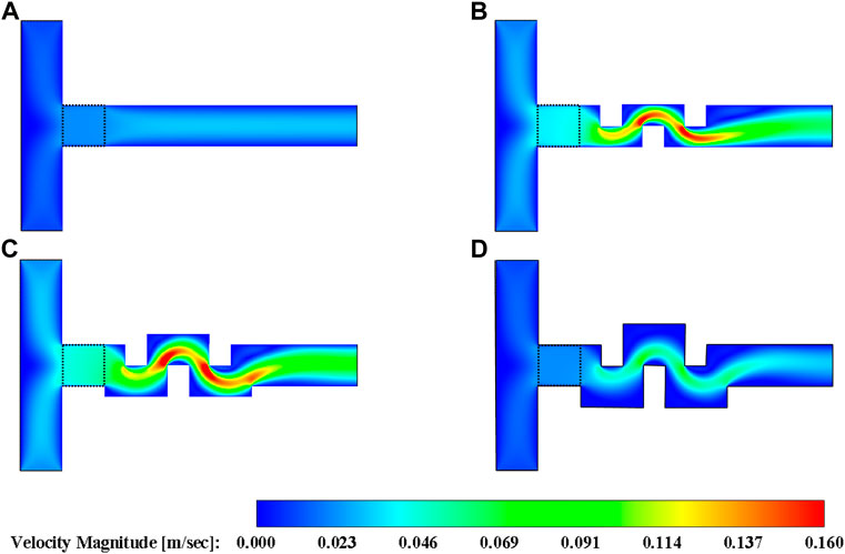
Figure 7. Velocity magnitude contours obtained for Re = 25, σ = 0.0001, Pr = 0.7 and ε = 0.7. Comparison between the (A) simple channel and the step-shaped channel with (B) h/H = 0, (C) h/H = 0.25, and (D) h/H = 0.5.
The total heat transfer between the fluid and the mixing channel wall and the average Nusselt number in the mixing channel are depicted in Figures 8A,B, respectively, for different Reynolds numbers and various models. Both figures exhibit the same trend with different values and slopes. According to Figure 8A, the micromixer with a step-shaped mixing channel shows a higher heat transfer rate to the mixing channel walls in comparison with the base channel. Also, among the studied cases of the step-shaped micromixer with different h/H values, the ratio h/H = 0 displays the highest heat transfer rate for all Reynolds numbers. For instance, at Re = 25 and h/H = 0, the heat transfer is enhanced by 15.38, 50, and 150% compared to the cases with h/H = 0.25, 0.5, and the simple mixing channel, respectively. Furthermore, at Re = 100, these improvements at h/H = 0 receive 19.56, 27.91, and 323.1%. Moreover, by comparing Figures 8A,B, it can be concluded that the trend for the average Nusselt number as a function of the Reynolds number remains the same for all cases.
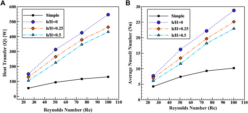
Figure 8. (A) Total heat transfer to the mixing channel wall, and (B) average Nusselt number in the mixing channel as a function of the Reynolds number for four configurations. Results were obtained for Pr = 0.7, ε = 0.7, and σ = 0.0001.
To better compare the influence of the h/H ratio in the step-shaped mixing channel on the heat transfer process and thermal mixing, the temperature contours for each case and different Reynolds numbers are illustrated in Figure 9. Firstly, it can be seen that as the Reynolds number increases, precisely at the outlet of the porous zone, thermal mixing performance declines. So, the temperature difference between the mixed fluid (at the inlet of the mixing channel) and the mixing channel wall rises, leading to an increase in the heat transfer rate between the mixed fluid and the channel wall. Also, as the ratio of h/H decreases at a constant Reynolds number, the cooling process becomes higher because the generated vortices in the corners get more compact. Moreover, at a low Reynolds number (Re = 25), there is no red region in the porous zone, which means that better thermal mixing is achieved. As the Reynolds number increases, a larger red region is shown in the porous zone.
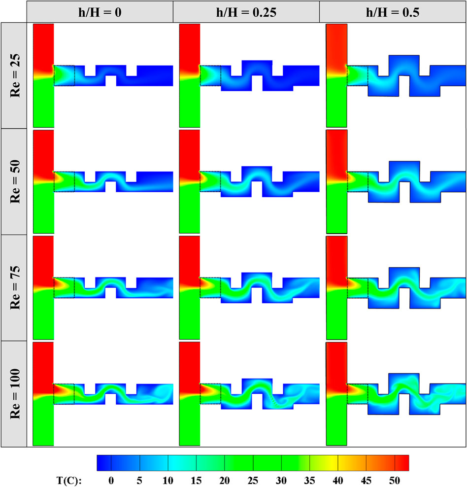
Figure 9. Temperature contours for different cases of step-shaped mixing channel and various Reynolds numbers at Pr = 0.7, ε = 0.7, and σ = 0.0001.
The schematic of the considered T-shaped micromixer is illustrated in Figure 1. The square porous block is placed precisely at the entrance of the mixing channel. Here, two different values of the h/H ratio, including 0.5 and 1, are considered. The obtained results of the zigzag-shaped mixing channel are compared with those of the simple mixing channel. The porosity and thermal conductivity ratio are kept constant to ε = 0.7 and σ = 0.001, similar to the previous section. The studied Reynolds number ranges between 25 and 100. Because of the contact between the porous block and the mixing channel wall at 0°C, the convection between the mixed fluid and the mixing channel wall occurs in the porous zone. After the porous zone, the heat transfer is mainly governed by forced convection (cooling process).
The vertical temperature profiles at the outlet of the zigzag-shaped mixing channel for 3 h/H ratios are displayed in Figure 10. Results were obtained for the T-shaped micromixer with a zigzag-shaped channel at Re = 25, Pr = 0.7, ε = 0.7, and σ = 0.0001. Firstly, employing a zigzag-shaped mixing channel with any value of h/H ratio leads to a lower average temperature at the outlet of the mixing channel compared to the simple mixing channel. Secondly, better mixing and cooling performance belongs to the case with zigzag-shaped mixing channel and h/H = 0.5.

Figure 10. Vertical temperature profile at the outlet of the zigzag-shaped mixing channel for 3 h/H ratios at Re = 25, Pr = 0.7, ε = 0.7, and σ = 0.0001.
The temperature contours for various cases are displayed in Figure 11 at Re = 25. It can be seen that for cases h/H = 0.5 and h/H = 1, the mixing channel length is larger than the simple case, which leads to better thermal mixing and cooling processes. Also, at the same Reynolds number, the temperature distribution in the porous block remains the same, and the differences appear only after the porous block. Moreover, it is worth mentioning that the differences between the cases h/H = 0.5 and h/h = 1 in Figure 11 are very weak. The average fluid temperature at the outlet and the average fluid temperature in the mixing channel are illustrated in Figures 12A,B, respectively, as a function of the Reynolds number for various models.
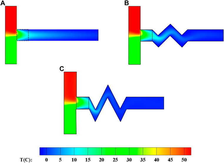
Figure 11. Temperature contours the T-micromixer with the step-shaped mixing channel. Results obtained for Re = 25, Pr = 0.7, ε = 0.7 and σ = 0.0001: (A) simple, (B) h/H = 0.5, and (C) h/H = 1.
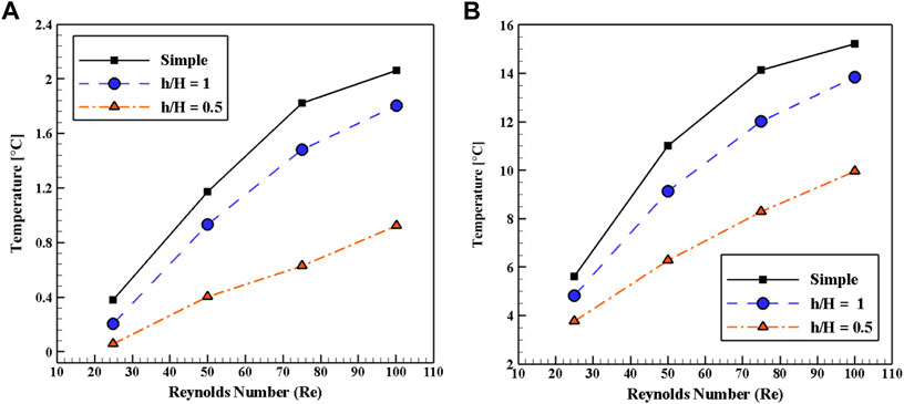
Figure 12. (A) Averaged fluid temperature at the channel outlet (x/H = 8), and (B) averaged fluid temperature in the mixing channel (from x/H = 1–8) as a function of the Reynolds number for three configurations and Pr = 0.7, ε = 0.7 and σ = 0.0001.
Firstly, Figure 12 shows that the trend remains the same: as the Reynolds number increases, the temperature rises. Secondly, it is shown that the highest and lowest temperature values belong to cases with a simple mixing channel and the zigzag case with h/H = 0.5. In other words, as the simple mixing channel has been changed to the zigzag one, the mixing length increases, leading to high thermal mixing. Also, the growth in Reynolds number decreases the mixing process time, which causes lower thermal mixing. To clarify the impact of the shape of the mixing channel on the thermal mixing and cooling processes, the velocity magnitude contours are depicted in Figure 13 for various models in the zigzag-shaped mixing channel at Re = 25.
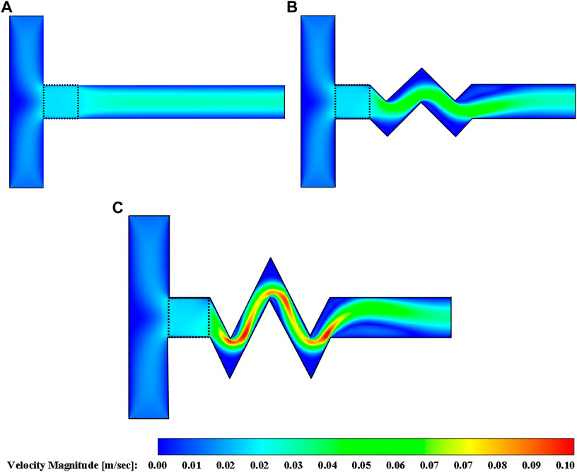
Figure 13. Velocity magnitude contours for the zigzag-shaped mixing channel at Re = 25, σ = 0.0001, Pr = 0.7 and ε = 0.7: (A) simple, (B) h/H = 0.5, and (C) h/H = 1.
Figure 13 illustrates that utilizing a zigzag-shaped mixing channel leads to a lower area of the mixing channel, and consequently, the velocity magnitude increases. The case with a zigzag-shaped mixing channel and h/H = 1 exhibits higher velocity magnitude, which leads to a lower heat transfer rate because the fluid retention time with the ultra-laminar fluid flow is reduced in the proposed micromixer and consequently, the heat exchange time of the mixed fluid with the cold wall (with 0 °C) is reduced.
The total heat transfer and average Nusselt number in the zigzag-shaped mixing channel are presented in Figures 14A,B, respectively, for various models as a function of the Reynolds number. Accordingly, it can be concluded that, firstly, in all considered values of h/H, employing a zigzag-shaped mixing channel causes more heat transfer rate and average Nusselt number compared to the simple mixing channel. Moreover, it is clear that as the Reynolds number increases, the differences rise among the various cases. Secondly, the case with h/H = 0.5 presents a higher heat transfer rate and average Nusselt number compared to other cases in all considered Reynolds numbers.

Figure 14. (A) Total heat transfer to the mixing channel wall, and (B) average Nusselt number in the zigzag-shaped mixing channel for different geometries and Reynolds numbers at Pr = 0.7, ε = 0.7, and σ = 0.0001.
The temperature contours for different cases of zigzag-shaped mixing channel and various Reynolds numbers are displayed in Figure 15. In Figure 15, all cases with any value of h/H perform better than the simple straight channel. Also, at a constant Reynolds number, the differences between the cases with a zigzag-shaped mixing channel are insignificant.
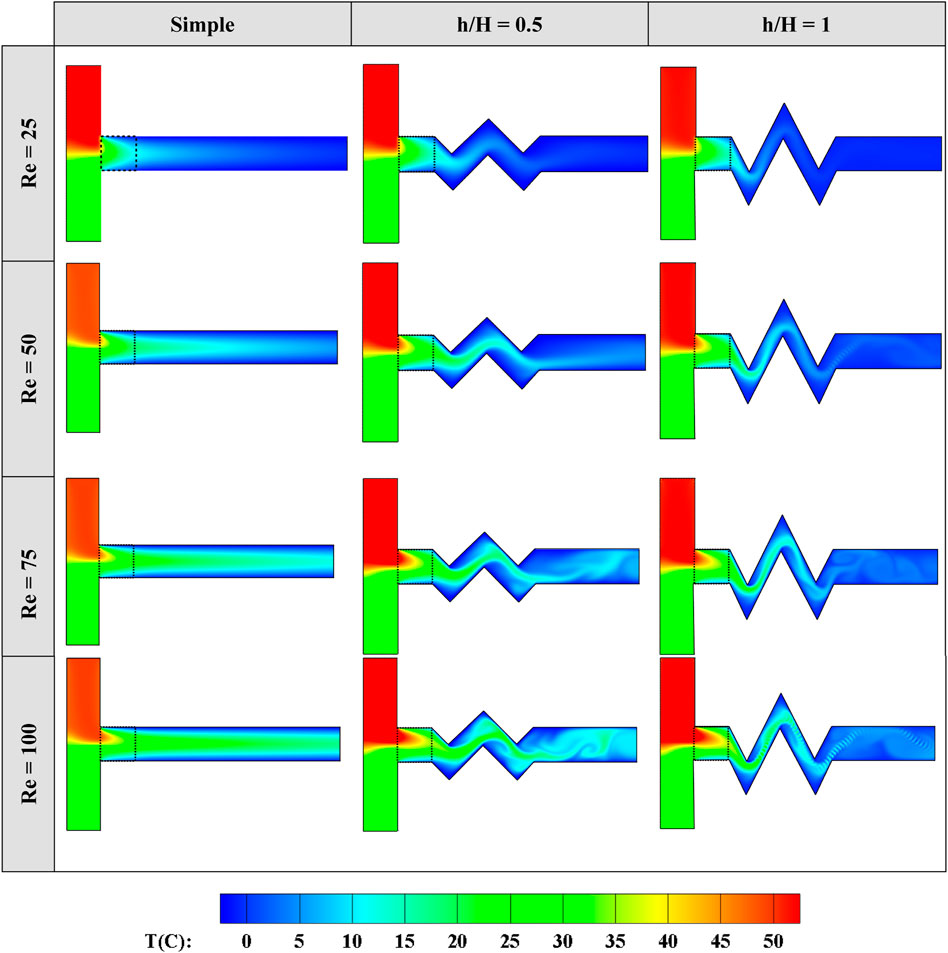
Figure 15. Temperature contours for the zigzag-shaped mixing channel geometries and various Reynolds numbers at Pr = 0.7, ε = 0.7, and σ = 0.0001.
In this section, a comparison between the best models of both zigzag-shaped and step-shaped cases is achieved. The T-shaped micromixer with a step-shaped mixing channel and h/H = 0, and the T-shaped micromixer with a zigzag-shaped mixing channel and h/H = 0.5 are selected as being the best geometrical models according to Sections 4.3, 4.4.
Firstly, the average fluid temperature in the mixing channel and the average fluid temperature at the outlet versus different Reynolds numbers for various models are presented in Figures 16A,B, respectively. According to Figure 16A, both cases with an advanced mixing channel shape exhibit a lower average temperature compared to the straight case, which means that the proposed micromixer could perform cooling and mixing processes successfully. Also, in all considered Reynolds numbers, the T-micromixer with the step-shaped mixing channel with the ratio of h/H = 0 shows a lower average temperature, leading to better thermal mixing and, consequently, more heat transfer between the mixed flow and the mixing channel wall (cooling process). The trend of the illustrated profiles in Figure 16B as the outlet average temperature is the same as Figure 16A. However, the differences between the models are lower than Figure 16A because along the mixing channel, the mixed fluid has enough time to transfer the heat with the mixing channel wall with zero degree.
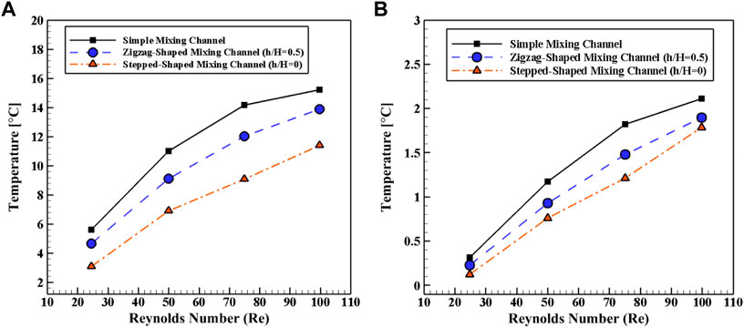
Figure 16. Averaged fluid temperatures (A) in the mixing channel and (B) at the outlet as a function of the Reynolds number for ε = 0.7, Pr = 0.7, and σ = 0.0001.
To clarify the impact of the mixing channel shape on the cooling process and especially on the thermal mixing, the contours of temperature and velocity magnitude for these three cases are demonstrated in Figure 17. The legend of both contours for all cases is set at the same range to ease comparison. Accordingly, the step-shaped and zigzag-shaped mixing channels exhibit a more suitable temperature distribution in terms of values and homogeneity compared to the simple channel. The velocity magnitude depicts the influence of the shape of the mixing channel on the cooling process. In other words, it can be seen that the step-shaped mixing channel causes an increase in velocity magnitude, which leads to a higher heat transfer rate. Obviously, the difference between the first and second cases based on the maximum velocity magnitude is significant. Temperature contours show that till the outlet of the porous block in all three cases, the mixing process offers the same trend. The differences appear exactly after the porous block.
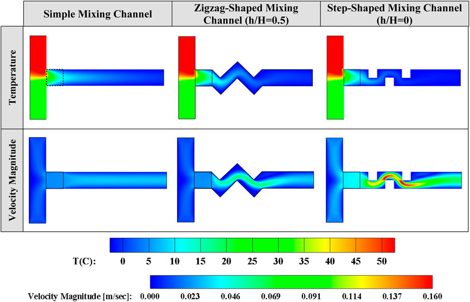
Figure 17. Temperature and velocity magnitude contours for the simple, the zig-zag-shaped, and step-shaped mixing channels for Pr = 0.7, ε = 0.7, Re = 25, and σ = 0.0001.
The total heat transfer and average Nusselt number in the mixing channel are illustrated in Figures 18A,B, respectively, for different Reynolds numbers and models. The difference between these cases remains weak at a low Reynolds number. As the Reynolds number rises, the heat transfer rate and consequently the average Nusselt number increases because of forced convection. For instance, at the lowest considered Reynolds number, Re = 25, the micromixer with the step-shaped mixing channel (h/H = 0) exhibits a heat transfer rate enhanced by 100 and 200% compared to the micromixers with the zigzag-shaped (h/H = 0.5) and simple mixing channels, respectively. Furthermore, at the highest considered Reynolds number, Re = 100, the micromixer with the step-shaped mixing channel (h/H = 0) exhibits a higher heat transfer rate (enhancement by 150 and 323.1% compared to the micromixers with the zigzag-shaped (h/H = 0.5) and simple mixing channels, respectively. The trend for the average Nusselt number remains the same compared to Figure 18A, but with different slopes.
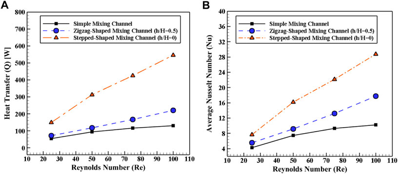
Figure 18. (A) Total heat transfer to the mixing channel wall, and (B) average Nusselt number in the mixing channel as a function of the Reynolds number for Pr = 0.7, ε = 0.7, and σ = 0.0001.
The velocity and temperature contours are displayed in Figure 19 for these three cases to clarify the impact of the mixing channel shape on the heat transfer rate and mixing process. The step-shaped and zigzag-shaped mixing channels cause chaotic flows leading to an increase in the velocity magnitude and, consequently a higher heat transfer rate. Also, for the step- and zigzag-shaped mixing channels, the velocity vectors in the corners are tiny, highlighting a vortical flow in those regions. Creating vortex flows even in the laminar regime (chaotic flow) leads to a higher heat transfer rate.
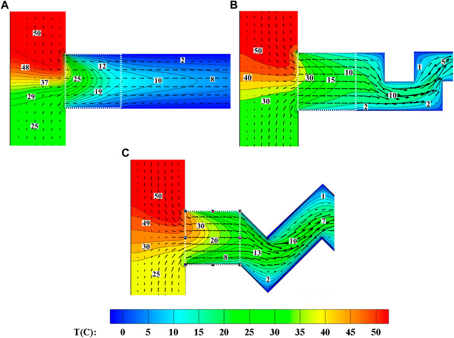
Figure 19. Velocity vectors and temperature contours for the T-micromixer with a (A) simple mixing channel, (B) step-shaped mixing channel (h/H = 0), and (C) zigzag-shaped mixing channel (h/H = 0.5) at Re = 25, Pr = 0.7, ε = 0.7, and σ = 0.0001.
Extensive recirculation (red circles) appears in the channel corners for the cases with a step-shaped and a zigzag-shaped mixing channel, as shown in Figure 20. These vortexes are created due to the change in the mixing channel geometry, and they are known to enhance thermal mixing. The thermal mixing is significantly improved by inserting a porous block exactly at the junction between the cold and hot streams.
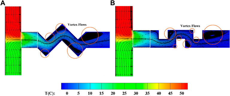
Figure 20. Streamlines and temperature contours for the T-micromixer with a (A) zigzag-shaped and a (B) step-shaped mixing channel at Re = 25, Pr = 0.7, ε = 0.7, and σ = 0.0001.
The thermal mixing and cooling processes were evaluated numerically in different T-micromixers. To improve the performance of the device, a porous block was inserted precisely at the collision point of two hot and cold streams, and the mixing channel shape was changed. The numerical solver is based on the D2Q9 thermal Lattice Boltzmann Method. The properties of the porous block, including its porosity and permeability, have been kept constant. Different micromixers with either a step-shaped or a zigzag-shaped mixing channel and various h/H ratios have been analyzed separately. Finally, the best cases in each section have been compared with each other. The obtained results can be summarized as follows:
- Using a step-shaped or a zigzag-shaped channel leads to a chaotic flow in the laminar regime and, thus, enhances the heat transfer between the fluid and the wall.
- For the T-shaped micromixer with a step-shaped mixing channel, as the ratio h/H increases (increasing the height of the mixing channel), the radius of the created vortexes in the corners of the channel rises, leading to a lower heat transfer rate.
- In the T-micromixer with a step-shaped mixing channel, at the lowest considered Reynolds number (Re = 25), the case with h/H = 0 enhances by 15.38, 50, and 150% the heat transfer compared to the cases with h/H = 0.25, 0.5, and the simple mixing channel, respectively. Furthermore, at the highest considered Reynolds number (Re = 100), the case with h/H = 0 enhances by 19.56, 27.91, and 323.1% the heat transfer compared to the cases with h/H = 0.25, 0.5, and the simple mixing channel, respectively.
- For the T-micromixer with the zigzag-shaped mixing channel, the case with h/H = 0.5 exhibits a higher velocity magnitude, which leads to a higher heat transfer rate because of forced convection.
- For the T-shaped micromixer with a zigzag-shaped mixing channel, the case with h/H = 1 has a lower peak temperature by up to 81.81 and 84.62% compared to the case with h/H = 0.5 and the simple mixing channel, respectively.
- At the lowest considered Reynolds number (Re = 25), the micromixer with a step-shaped mixing channel (h/H = 0) exhibits an enhanced heat transfer rate by up to 100 and 200% compared to the micromixer with a zigzag-shaped (h/H = 0.5) and a simple mixing channel, respectively. For Re = 100, these enhancements get 150 and 323.1%, respectively.
According to the obtained results, it can be concluded that employing the proposed geometries of the mixing channel equipped with a porous block at its entrance leads to a better thermal mixing in comparison with the simple straight case. Consequently, it can be considered a very influential issue on the thermal performance of micromixers, and an experimental study of the proposed models could be an interesting topic for future research in order to confirm the present findings.
The raw data supporting the conclusion of this article will be made available by the authors, without undue reservation.
SA and SP contributed to conception and design of the study. SA organized the database. SA performed the numerical analysis. SA wrote the first draft of the manuscript. SA and SP wrote sections of the manuscript. All authors contributed to manuscript revision, read, and approved the submitted version.
The authors declare that the research was conducted in the absence of any commercial or financial relationships that could be construed as a potential conflict of interest.
All claims expressed in this article are solely those of the authors and do not necessarily represent those of their affiliated organizations, or those of the publisher, the editors and the reviewers. Any product that may be evaluated in this article, or claim that may be made by its manufacturer, is not guaranteed or endorsed by the publisher.
Afrouzi, H. H., Ahmadian, M., Moshfegh, A., Toghraie, D., and Javadzadegan, A. (2019). Statistical analysis of pulsating non-Newtonian flow in a corrugated channel using Lattice-Boltzmann method. Phys. A Stat. Mech. its Appl. 535, 122486. . doi:10.1016/j.physa.2019.122486
Alazmi, B., and Vafai, K. (2001). Analysis of fluid flow and heat transfer interfacial conditions between a porous medium and a fluid layer. Int. J. Heat Mass Transf. 44, 1735–1749. doi:10.1016/s0017-9310(00)00217-9
Balootaki, A. A., Karimipour, A., and Toghraie, D. (2018). Nano scale lattice Boltzmann method to simulate the mixed convection heat transfer of air in a lid-driven cavity with an endothermic obstacle inside. Phys. A Stat. Mech. Its Appl. 508, 681–701. . doi:10.1016/j.physa.2018.05.141
Baragh, S., Shokouhmand, H., Ajarostaghi, S. S. M., and Nikian, M. (2018). An experimental investigation on forced convection heat transfer of single-phase flow in a channel with different arrangements of porous media. Int. J. Therm. Sci. 134, 370–379. . doi:10.1016/j.ijthermalsci.2018.04.030
Baragh, S., Shokouhmand, H., and Mousavi Ajarostaghi, S. S. (2019). Experiments on mist flow and heat transfer in a tube fitted with porous media. Int. J. Therm. Sci. 137, 388–398. . doi:10.1016/j.ijthermalsci.2018.11.030
Cho, E. S., Choi, J. W., Yoon, J. S., and Kim, M. S. (2010). Modeling and simulation on the mass flow distribution in microchannel heat sinks with non-uniform heat flux conditions. Int. J. Heat Mass Transf. 53, 1341–1348. doi:10.1016/j.ijheatmasstransfer.2009.12.025
Chuang, G. Y., and Ferng, Y. M. (2017). Experimentally investigating the thermal mixing and thermal stripping characteristics in a T-junction. Appl. Therm. Eng. 113, 1585–1595. doi:10.1016/j.applthermaleng.2016.10.157
Douroum, E., Laouedj, S., Kouadri, A., Naas, T. T., Khelladi, S., and Benazza, A. (2021). High hydrodynamic and thermal mixing performances of efficient chaotic micromixers: A comparative study. Chem. Eng. Process. - Process Intensif. 164, 108394. doi:10.1016/j.cep.2021.108394
Evrim, C., and Laurien, E. (2021). Numerical study of thermal mixing mechanisms in T-junctions. Appl. Therm. Eng. 183, 116155. doi:10.1016/j.applthermaleng.2020.116155
Feng, T., Wang, M., Song, P., Liu, L., Tian, W., Su, G. H., et al. (2019). Numerical research on thermal mixing characteristics in a 45-degree T-junction for two-phase stratified flow during the emergency core cooling safety injection. Prog. Nucl. Energy 114, 91–104. doi:10.1016/j.pnucene.2019.03.009
Fletcher, P. D. I., Haswell, S. J., Pombo-Villar, E., Warrington, B. H., Watts, P., Wong, S. Y. F., et al. (2004). Micro reactors: Principles and applications in organic synthesis. Tetrahedron 58 (24), 4735–4757. doi:10.1016/s0040-4020(02)00432-5
Gobby, D., Angeli, P., and Gavrilidis, A. (2001). Mixing characteristics of T-type microfluidic mixers. J. Micromech. Microeng. 11, 126–132. doi:10.1088/0960-1317/11/2/307
Guo, Z., and Zhao, T. C. (2002). Lattice Boltzmann model for incompressible flows through porous media. Phys. Rev. E 66, 036304. doi:10.1103/physreve.66.036304
Jourabian, M., Darzi, A. A. R., Toghraie, D., and Ali Akbari, O. (2018). Melting process in porous media around two hot cylinders: Numerical study using the lattice Boltzmann method. Phys. A Stat. Mech. its Appl. 509, 316–335. doi:10.1016/j.physa.2018.06.011
Kays, W. M., and Crawford, M. (1993). Solutions manual, convective heat and mass transfer. 3rd ed., 9. New-York: McGraw-Hill–1.
Kazemi Moghadam, H., Mousavi Ajarostaghi, S. S., and Poncet, S. (2020). Extensive numerical analysis of the thermal performance of a corrugated tube with coiled wire. J. Therm. Anal. Calorim. 140 (3), 1469–1481. . doi:10.1007/s10973-019-08876-4
Kazemi Moghadam, H., Mousavi Ajarostaghi, S. S., and Poncet, S. (2021). Numerical modeling of an innovative arc shape rib based solar air heater. Proc. Institution Mech. Eng. Part C J. Mech. Eng. Sci. 235 (24), 7992–8012. . doi:10.1177/09544062211039541
Mousavi Ajarostaghi, S. S., Zaboli, M., Javadi, H., Badenes, B., and Urchueguia, J. F. (2022). A review of recent passive heat transfer enhancement methods. Energies 15 (3), 986. . doi:10.3390/en15030986
Mu, Y.-T., Chen, L., He, Y.-L., and Tao, W.-Q. (2015). Numerical study on temperature uniformity in a novel mini-channel heat sink with different flow field configurations. Int. J. Heat Mass Transf. 85, 147–157. doi:10.1016/j.ijheatmasstransfer.2015.01.093
Myers, K. J., Bakker, A., and Ryan, D. (1997). Avoid agitation by selecting static mixers. Chem. Eng. Prog. 93 (6), 28–38.
Narendran, G., Gnanasekaran, N., and Perumal, D. A. (2018). A review on recent advances in microchannel heat sink configurations. Recent Pat. Mech. Eng. 11 (3), 190–215. doi:10.2174/2212797611666180726124047
Nemati, M., Abady, A. R. S. N., Toghraie, D., and Karimipour, A. (2018). Numerical investigation of the pseudopotential lattice Boltzmann modeling of liquid–vapor for multi-phase flows. Phys. A Stat. Mech. its Appl. 489, 65–77. . doi:10.1016/j.physa.2017.07.013
Selvam, P. K., Kulenovic, R., Laurien, E., Kickhofel, J., and Prasser, H. M. (2017). Thermal mixing of flows in horizontal T-junctions with low branch velocities. Nucl. Eng. Des. 322, 32–54. doi:10.1016/j.nucengdes.2017.06.041
Siddiqui, O. K., and Zubair, S. M. (2017). Efficient energy utilization through proper design of microchannel heat exchanger manifolds: A comprehensive review. Renew. Sustain. Energy Rev. 74, 969–1002. doi:10.1016/j.rser.2017.01.074
Su, B., Zhu, Z., Wang, X., Ke, H., Lin, M., and Wang, Q. (2020). Effect of temperature difference on the thermal mixing phenomenon in a T-junction under inflow pulsation. Nucl. Eng. Des. 363, 110611. doi:10.1016/j.nucengdes.2020.110611
Teggar, M., Ajarostaghi, S. S., Yıldız, Ç., Arıcı, M., Ismail, K. A., Niyas, H., et al. (2021). Performance enhancement of latent heat storage systems by using extended surfaces and porous materials: A state-of-the-art review. J. Energy Storage 44, 103340. . doi:10.1016/j.est.2021.103340
Toghaniyan, A., Zarringhalam, M., Akbari, O. A., Shabani, G. A. S., and Toghraie, D. (2018). Application of lattice Boltzmann method and spinodal decomposition phenomenon for simulating two-phase thermal flows. Phys. A Stat. Mech. its Appl. 509, 673–689. . doi:10.1016/j.physa.2018.06.030
Tullius, J. F., Vajtai, R., and Bayazitoglu, Y. (2011). A review of cooling in microchannels. Heat. Transf. Eng. 32 (8), 527–541. doi:10.1080/01457632.2010.506390
Wasewar, K. L., and Sarathi, J. V. (2008). CFD modelling and simulation of jet mixed tanks. Eng. Appl. Comput. Fluid Mech. 2, 155–171. doi:10.1080/19942060.2008.11015218
Wong, S. H., Ward, M. C. L., and Wharton, C. W. (2004). Micro T-mixer as a rapid mixing micromixer. Sensors Actuators B Chem. 100, 359–379. doi:10.1016/j.snb.2004.02.008
Zhou, M., Kulenovic, R., and Laurien, E. (2019). Advanced flow pattern for describing tangential flow oscillation in thermal-mixing pipe flow at a horizontal T-Junction. Int. J. Therm. Sci. 136, 328–336. doi:10.1016/j.ijthermalsci.2018.10.045
Zhou, M., Kulenovic, R., and Laurien, E. (2018). Experimental investigation on the thermal mixing characteristics at a 90° T-Junction with varied temperature differences. Appl. Therm. Eng. 128, 1359–1371. doi:10.1016/j.applthermaleng.2017.09.118
Zhou, M., Kulenovic, R., and Laurien, E. (2019). T-junction experiments to investigate thermal-mixing pipe flow with combined measurement techniques. Appl. Therm. Eng. 150, 237–249. doi:10.1016/j.applthermaleng.2018.12.161
c Discrete lattice velocity
Da Darcy number [-]
f Distribution function for flow fluid
F Acceleration due to external force, [m.s−2]
g Distribution function for temperature
G Gravity acceleration, [m.s−2]
H Characteristic height, [m]
K Permeability, [m2]
k Thermal Conductivity, [W.m−1.K−1] lattice model direction
Nu Local Nusselt number, [-]
P Pressure, [pa]
Pr Prandtl number, [-]
Q Heat transfer to the horizontal wall, [W]
Re Reynolds number, [-]
r Ratio [-]
t Time, [s]
T Temperature, [K]
u Velocity component, [m.s−1]
x Dimension, [m]
ε Porosity, [-]
µ Dynamic viscosity, [Pa.s]
ρ Density, [kg.m−3]
σ Conductivity ratio, [-]
υ Kinematic viscosity, [m2.s−1]
τ Relaxation time
ω Weighting factor
α Diffusivity, [m2..s−1]
β Angle between the two inlet streams [°]
eff effective
eq equilibrium distribution function
i, j dimension directions
q heat flux
k Thermal Conductivity, [W.m−1.K−1] lattice model direction
gen total generated
f Distribution function for flow fluid
s solid
in inlet
Keywords: micromixer, lattice Boltzmann method, porous medium, passive cooling, Numerical Simulation, Heat Transfer
Citation: Mousavi Ajarostaghi SS and Poncet S (2022) Thermal mixing in T-shaped micromixers with a porous block by the lattice Boltzmann method: Influence of the mixing channel configuration. Front. Therm. Eng. 2:961083. doi: 10.3389/fther.2022.961083
Received: 03 June 2022; Accepted: 16 August 2022;
Published: 23 September 2022.
Edited by:
Rajan Kumar, Dr. B. R. Ambedkar National Institute of Technology Jalandhar, IndiaReviewed by:
Jianfeng Pan, Jiangsu University, ChinaCopyright © 2022 Mousavi Ajarostaghi and Poncet. This is an open-access article distributed under the terms of the Creative Commons Attribution License (CC BY). The use, distribution or reproduction in other forums is permitted, provided the original author(s) and the copyright owner(s) are credited and that the original publication in this journal is cited, in accordance with accepted academic practice. No use, distribution or reproduction is permitted which does not comply with these terms.
*Correspondence: Sébastien Poncet, U2ViYXN0aWVuLlBvbmNldEB1c2hlcmJyb29rZS5jYQ==
Disclaimer: All claims expressed in this article are solely those of the authors and do not necessarily represent those of their affiliated organizations, or those of the publisher, the editors and the reviewers. Any product that may be evaluated in this article or claim that may be made by its manufacturer is not guaranteed or endorsed by the publisher.
Research integrity at Frontiers
Learn more about the work of our research integrity team to safeguard the quality of each article we publish.