 Z. N. Duan
 G. B. Zhang
 J. F. Zhang
 Z. G. Qu
94% of researchers rate our articles as excellent or good
Learn more about the work of our research integrity team to safeguard the quality of each article we publish.
Find out more
ORIGINAL RESEARCH article
Front. Therm. Eng., 05 August 2022
Sec. Heat Engines
Volume 2 - 2022 | https://doi.org/10.3389/fther.2022.931160
This article is part of the Research TopicThermal Management of Electrochemical Energy Devices or SystemsView all 6 articles
All-vanadium redox flow battery (VRFB) is a promising energy storage technique. Flow fields play a crucial role in distributing the electrolyte into the electrode uniformly, but their performance characteristics under different electrode parameters are still unclear. In this work, taking the total pressure drop and total overpotential as performance characterizations, the influence of electrode parameters and operating conditions on the performance of serpentine flow field (SFF) and interdigitated flow field (IFF) are experimentally investigated. It is found that the battery with IFF exhibits lower pressure drop than that with SFF because of the shunt effect of IFF on electrolyte. In terms of promoting the uniform distribution of the electrolyte into the electrode, the SFF outperforms IFF when the electrode porosity is higher than 0.810, but the performance of SFF and IFF could be reversed as the electrode porosity decreases to 0.714, indicating that there may be a performance reversal between SFF and IFF when the electrode porosity decreases from 0.810 to 0.714. Moreover, the increase of current density, the decrease of electrolyte input, and the decrease of electrode thickness strengthen the performance reversal at low electrode porosity. The results well explain the debate on the superiority of IFF and SFF and the discussion on the preference between flow fields and electrode thickness in literatures and provide guidance for the selection of optimal flow field in VRFBs.
Renewable energy such as solar energy, wind energy, and tidal energy has become an important part in power supply. However, since the output of renewable energy is fluctuant, the direct integration of renewable energy with the grid may cause the instability of the grid (Yang et al., 2011). The all-vanadium redox flow battery (VRFB) is a novel electrochemical energy storage technique, and it has the merits of environmental friendliness, high efficiency, deep discharge, and long service life. In addition, the output power and storage capacity of the VRFB are independent with each other, which allows the VRFB to achieve the flexible design of electrical energy storage from kilowatts to megawatts. Therefore, the VRFB provides an effective way to bridge the renewable energy and the grid smoothly and maintain the safe operation of the grid (Amirante et al., 2017).
The VRFB suffers from activation polarization loss, ohmic polarization loss, and concentration polarization loss during operation, which results in the reduction in output power and system efficiency (Duan et al., 2021). To promote the performance of the VRFB, great efforts have been taken from the perspective of the material characteristics and geometric structures. The activation polarization loss depends on the catalyst (Arenas et al., 2017). The commonly used methods to enhance the catalytic activity of electrode include the surface hybridization and surface deposition, like the doping of non-metallic atoms such as nitrogen (Wu et al., 2016) and oxygen (Kim et al., 2014) and the deposition of metal compounds such as NiCoO2 (Xiang and Daoud, 2019) and Nd2O3 (Fetyan et al., 2018). The ohmic polarization loss could be restrained by increasing the concentration of supporting electrolyte (Li et al., 2011), enhancing the permeability of membrane (Minke and Turek, 2015) and the appropriate compression of electrode (Ghimire et al., 2018; Wang et al., 2018). The electrolyte permeation in a porous electrode prefers the pathway with the least permeation resistance, which may deteriorate the uniformity of electrolyte distribution and increase the concentration polarization loss (Tariq et al., 2018). In view of this, the flow fields are introduced to guide the homogeneous distribution of electrolyte, which is generally engraved on the surface of a bipolar plate adjacent to the electrode.
The common flow fields in the VRFB are the interdigitated flow field (IFF) and serpentine flow field (SFF). The IFF consists of an inlet manifold, an outlet manifold, and multiple death-ended channels that are connected with the inlet manifold or outlet manifold in turn. When the electrolyte enters the battery with the IFF, the electrolyte from the inlet manifold is first shunted by inlet channels. Then, the electrolyte gradually penetrates the porous electrode as the electrolyte flows along the inlet channels. Finally, the electrolyte that has completed the electrochemical reaction in porous electrode is collected by outlet channels and flows out through the outlet manifold. The shunt process of electrolyte flow induced by the IFF, known as the “shunt effect,” can promote the uniform distribution of electrolyte at an acceptable pressure drop. Meanwhile, the death-ended design forces the entire electrolyte to permeate into electrodes, which contributes to improving the utilization of electrode and electrolyte (Reed et al., 2016). The SFF has a continuous and meandering channel connecting the inlet and outlet. The high-electrolyte flux in the channel and the severe disturbance along the channel produce a huge pressure drop between adjacent channels, which drives the electrolyte to penetrate the electrode (Ke et al., 2018). Obviously, the SFF and IFF have significant divergence in structure and working principle.
To determine the applicability of SFF and IFF, the comparison between IFF and SFF has been conducted. Kumar and Jayanti (2016) investigated the discharging potential of the battery with IFF and the battery with SFF under various current densities and electrolyte inputs. The results showed that the battery with SFF always had higher discharging potential than the battery with IFF, and the peak power density of the battery with SFF was 30% higher than that with IFF. The authors attributed this phenomenon to the excessive parallel channels in IFF, which made the electrolyte flow rate in each channel very low and thereby resulted in a poor electrolyte penetration in through-plane direction. In addition, Maurya et al. (2018) and Messaggi et al. (2018) also investigated the discharging performance of the batteries with SFF and IFF through experiments and simulations. The experimental results confirmed that the battery with SFF provided higher discharging potential than that with IFF. By simulating the electrolyte flow in two batteries, the authors found that the electrolyte flow rate in the battery with SFF was higher than that in the battery with IFF, and the authors believed that this was the reason for the better discharging performance of the battery with SFF. However, the experiments conducted by Tsushima et al. (2013) obtained opposite conclusions. The experimental results showed that the discharging potential of the battery with IFF was always higher than that with SFF, which indicated that the IFF performed better than the SFF. In addition, Jyothi Latha and Jayanti (2014) also found that the battery with IFF owned higher discharging potential and power density than that with SFF. Meanwhile, the numerical analysis indicated that the residence time of electrolyte in the battery with IFF was shorter than that with SFF, which means that the electrolyte transport in the battery with IFF was faster. Furthermore, Houser et al. (2016); Houser et al. (2017) even observed the performance reversal between the batteries with IFF and SFF. At electrolyte input of 90 ml min−1 and current density of 250 mA cm−2, the discharging potential of the battery with IFF was lower than that of the battery with SFF, while maintaining the electrolyte input unchanged but increasing the current density to 500 mA cm−2, the discharging potential of the battery with IFF exceeded that of the battery with SFF.
Obviously, the researches on the superiority of the IFF and SFF have not reached a unified conclusion; the fundamental reason might be the electrode parameters. The SFF and IFF have distinct divergence in the working principle, which may result in the different responses of IFF and SFF to the changes in electrode parameters. For example, the porous electrode in the VRFB is compressed during the assembly process, which leads to a decrease in electrode porosity and permeability. For the battery with IFF, the death-ended design of IFF ensures that the entire electrolyte must permeate into the electrode, and thereby the electrode compression has no influence on the permeation flux in the battery with IFF. However, for the battery with SFF, the decrease in electrode porosity and permeability causes a decline in the permeation flux in the battery with SFF. The electrode parameters (including the porosity and thickness) in previous works are inconsistent, which is very likely to cause the different results. At present, only a few works involve the effect of electrode parameters. Messaggi et al. (2020) and Houser et al. (2016) investigated the performance of the batteries with electrodes of different thicknesses, and a rule that the IFF and SFF were preferable for the thinner and thicker electrode, respectively, was summarized. Nevertheless, the applicability of this rule lacks the support of quantitative investigations. Moreover, the hydrodynamic properties of electrode greatly depend on its porosity (permeability), which was seldom considered in previous studies. Thus, it is necessary to quantitatively analyze the influence of electrode parameters on the performance of flow fields.
In this work, the influence of electrode parameters on the performance of flow fields is experimentally investigated. By comparing the total pressure drop and total overpotential of the VRFB with IFF and the VRFB with SFF under various operating conditions and electrode parameters, the effects of electrode parameters on the performance of the IFF and SFF are quantitatively studied. Based on the obtained results, the effect of electrode parameters and operating conditions on the performance of IFF and SFF is summarized. The obtained conclusions can provide guidance for the selection of flow fields in VRFBs.
Figure 1 presents the schematic of the VRFB, which has a symmetrical structure with the membrane in middle. On both sides of the membrane, there are electrodes, bipolar plates, current collectors, and end plates. The commonly used membrane is the proton exchange membrane, which separates the positive and negative half-cells and allows only the proton to pass through. The electrode made of carbon fiber provides reaction sites for electrochemical reactions. The carbon-based bipolar plate and metal-based current collector jointly connect the electrode with external circuit. In addition, the flow fields such as SFF and IFF are grooved on the bipolar plates to strengthen the uniform distribution of electrolyte. The end plate bears the assembly force and provides mechanical support for the battery, which is usually prepared by metal with high mechanical strength. The anolyte and catholyte are prepared by dissolving VO2+/VO2+ and V3+/V2+ into supporting electrolyte (sulfuric acid solution), respectively. The electrolyte tanks are employed to store the electrolyte. As the battery operates, the electrolyte is transported into the electrode using a pump to realize the conversion between the electricity and chemical energy. During charging, the VO2+ is oxidized to VO2+ at the positive half-cell, meanwhile, the V3+ is reduced to V2+ at the negative half-cell. During discharging, the reaction processes reverse (Skyllas-Kazacos et al., 2011). The electrochemical reactions are as follows:
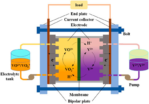
Figure 1. Schematic of the VRFB.
The purpose of this work is to investigate the performance of SFF and IFF in VRFB with electrodes of different porosities and thicknesses. The experiment is conducted based on a self-built experimental test system. Figure 2 provides the schematic of the experimental test system. The system mainly consists of the test batteries (the two VRFBs with IFF or SFF), the electrolyte tanks, the electrochemical workstation, the electronic data acquisition instrument, electrolyte circulating pumps, the pressure sensors, and the computer. The two VRFBs are connected to the electrolyte tanks in parallel to ensure that the state of electrolyte entering two batteries is the same. Meanwhile, the two VRFBs are connected to the electrochemical workstation in series to ensure that the current applied on the two batteries is equal. The terminal potential of the two batteries is measured by the electronic data acquisition instrument. The electrolyte supply is realized by circulating pumps, and the pressure sensors are connected to the inlet and outlet of each battery, respectively, to measure the pressure drop of each battery. In addition, considering that the catholyte could be oxidized by air, nitrogen is injected into the catholyte tank to isolate the air (Pezeshki et al., 2017).
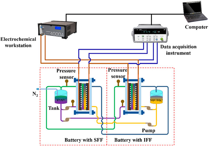
Figure 2. Schematic of the experimental test system.
Figure 3 shows the test platform of the VRFB. The connection of the electrolyte pipelines and wires in the test platform is the same as that in Figure 2. The electrochemical workstation (PARSTAT 4000, AMETEK, United States of America) can provide current in the range of -10 A–+10 A with a resolution of ±0.2%, and the terminal potential of the two batteries are recorded by a multi-channel electronic data acquisition instrument (34970A, Keysight Technologies, United States of America), with an accuracy of 0.0004 V. The electrochemical workstation and the electronic data acquisition instrument are controlled by the computer. The electrolyte circulating pumps are two peristaltic pumps (BT600N, Baoding Shenchen Precision Pump Co., Ltd., China), which have a flux range of 0.027–162 ml min−1. The pressure sensor (CYYZ11, Beijing XingSense Sensor Technology Co., Ltd., China)) has a range of 0–20 kPa, with an accuracy of 0.1 kPa. The flow rate of nitrogen is 100 ml min−1. The experiments are performed at room temperature (about 25 °C), and all tests are conducted three times to eliminate the accidental errors.
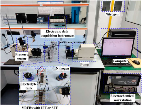
Figure 3. Test platform of the VRFB.
Two single VRFBs with IFF or SFF are assembled in this work. The only difference between the two VRFBs is the structure of the flow field. Figure 4 shows the geometric structures of IFF and SFF. The rib width, the channel width, and the channel depth (not presented in Figure 4) are all set to 2 mm. The proton exchange membrane (Nafion 212, DuPont, United States of America) is employed as the separator. The electrolyte used for the test contains 1.5 M Vn+ and 3 M H2SO4. The electrolyte volume in both anodic and cathodic tanks is 250 ml. The PAN-based graphite felt (Shanghai Carbon Plant, China) with a size of 70 mm × 70 mm × 1.3 mm is used as the electrode. Electrodes with different initial thicknesses are prepared by stacking the graphite felt. Figure 5 shows the schematic of electrodes with initial thicknesses of 5.2, 3.9, and 2.6 mm, which consist of four, three, and two layers of graphite felt, respectively. In addition, to obtain the electrodes with different porosities, electrodes with initial thicknesses of 5.2, 3.9, and 2.6 mm need to be properly compressed. Table 1 provides the relationship between electrode thickness and electrode porosity before and after compression. The thickness of the compressed electrode is controlled to ensure that the compressed electrode has the same porosity. The electrode porosity after compression is calculated according to Eq. 3 (Chi et al., 2010; Bromberger et al., 2014). For the convenience of description and reference, the assembled electrodes are named in the format of the number of graphite felt in the electrode—the porosity of the electrode after compression.
where h0 and hc denote the electrode thickness before and after compression, respectively. ε0 and εc denote the electrode porosity before and after compression, respectively.
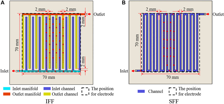
Figure 4. Geometric structure of IFF and SFF.
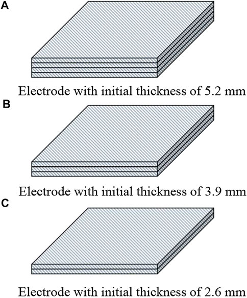
Figure 5. Schematic of electrodes with different initial thicknesses. (A) Electrode with initial thickness of 5.2 mm. (B) Electrode with initial thickness of 3.9 mm. (C) Electrode with initial thickness of 2.6 mm.
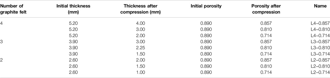
Table 1. Geometric parameters of electrodes.
The total pressure drop of a half-cell in each battery is measured to evaluate their flow behaviors. Considering that the electrolyte used in VRFBs is highly acidic and corrosive, which may damage the pressure sensors, the electrolyte is substituted by water. The total water input is set in the range of 27.0–67.5 ml min−1. Based on the measured fluid pressure at the inlet

Table 2. Total pressure drop test items.
The effects of IFF and SFF on the electrochemical performance of VRFBs are investigated by comparing the total overpotential of VRFBs with IFF or SFF. The detailed test processes are as follows: under the open-circuit condition, the open-circuit potential of the two VRFBs,
In the discharge test, there are no specified values for the SOC of electrolyte and discharge time, which can be determined according to the experimental requirements (Becker et al., 2016; Zeng et al., 2016). Considering that the effect of concentration polarization maybe insignificant when the SOC of electrolyte is very high, and the state of electrolyte may change obviously during the discharging process when the SOC of electrolyte is very low. Therefore, a moderate SOC of electrolyte is selected in this study, that is, the SOC of electrolyte is maintained at about 0.4. On the other hand, since the electrolyte is circulating during the test, the SOC of electrolyte decreases with the progress of the discharging test. In order to prevent the significant change in SOC of electrolyte during the test, the discharging time
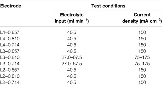
Table 3. Total overpotential test items.
In this section, the working principles of IFF and SFF are first analyzed. In addition, taking the total pressure drop and total overpotential as performance characterizations, the effect of electrode parameters such as porosity and thickness and operating conditions such as electrolyte input and current density on the performance of IFF and SFF are studied. The default current density and electrolyte input are 150 mA cm−2 and 40.5 ml min−1, respectively, unless otherwise stated, these parameters are maintained constant. Furthermore, based on the obtained results, the effect of electrode parameters and operating conditions on the performance of IFF and SFF is summarized, and reasonable explanations are given for the debate on the superiority of IFF and SFF in previous works.
The working principles of IFF and SFF are different due to their divergence in the geometric structure. Figure 6 shows the working principle of SFF and its hydrodynamic network model under ideal conditions. Figure 6A shows the electrolyte transport in the battery with SFF. The electrolyte flowing along the tortuous channels causes a high pressure drop between adjacent channels, which is the driving force for the electrolyte permeation into the electrode underneath ribs. The electrolyte transport between adjacent channels occurs sequentially, indicating that the electrolyte transport in the battery with SFF is a periodic process. Based on this, the battery with SFF is divided into n blocks along the centerline of channels (the black-dotted lines in Figure 6A) to better understand the working principle of SFF. Figure 6B presents the hydrodynamic network model of the battery with SFF under ideal conditions. The electrolyte transport in each block includes the free-flow in channels and the permeation flow in the electrode.
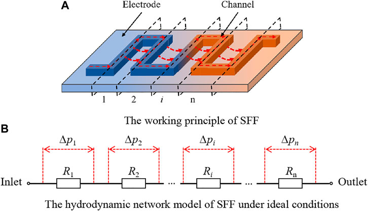
Figure 6. Working principle of SFF and its hydrodynamic network model. (A) Working principle of SFF. (B) Hydrodynamic network model of SFF under ideal conditions.
Similarly, Figure 7 presents the working principle of IFF and its hydrodynamic network model under ideal conditions. Figure 7A shows the electrolyte transport in the battery with IFF. The electrolyte from the inlet manifold is first shunted by inlet channels, and after the permeation in the electrode, the electrolyte is collected by outlet channels and flows out through the outlet manifold. Based on this process, the battery with IFF can be divided into three sections along the pink dot-dash lines in Figure 7A: the inlet manifold section, the parallel channel section (including the inlet channels, the electrode, and the outlet channels), and the outlet manifold section. Figure 7B provides the hydrodynamic network model of the battery with IFF under ideal conditions. The electrolyte flows through the inlet manifold section, the parallel channel section, and the outlet manifold section in sequence. Hence, the flow resistance of the inlet manifold section
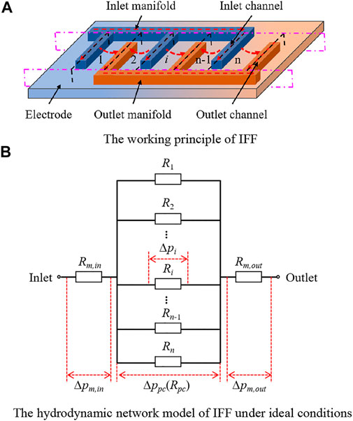
Figure 7. Working principle of IFF and its hydrodynamic network model. (A) Working principle of IFF. (B) Hydrodynamic network model of IFF under ideal conditions.
In addition, due to the shunt effect of the parallel channels, the electrolyte flow in the parallel channel section can be approximated as a symmetric process. Based on this, the parallel channel section is further segmented into n blocks along the black-dotted lines in Figure 7A. The electrolyte flow in each block includes the free-flow in the inlet channel, the permeation flow in the electrode, and the free-flow in the outlet channel, and the three processes occur sequentially. Taking the block i as an example, the flow resistance of electrolyte in channels and the electrode is represented by
The divergence in the working principle determines that the variation of electrode parameters has different effects on the performance of SFF and IFF. For example, the electrode compression causes a decrease in electrode porosity and an increase in permeation flow resistance of the electrode. For the battery with SFF, the free-flow flux in channels and the permeation flow flux in the electrode depend on the free-flow resistance of channels and the permeation flow resistance of the electrode. When the permeation flow resistance increases, the balance between the permeation flow in the electrode and the free-flow in the channel is disrupted, resulting in a decrease in the permeation flow flux and an increase in the free-flow flux. The electrolyte flow becomes stable again when the pressure drop of free-flow equals to the pressure drop of the permeation flow. As a result, the electrolyte flux permeating into the electrode decreases. For the battery with IFF, the death-ended design of IFF ensures all electrolytes to permeate into the electrode. Therefore, the permeation flow flux is always equal to the total electrolyte input, regardless of the permeation flow resistance. Obviously, the divergence in the working principle leads to the different responses of IFF and SFF to the changes of electrode parameters, which may cause the differences in output performance of VRFBs.
Using L3−0.857, L3−0.810, and L3−0.714 as electrodes, respectively, the total pressure drop and total overpotential of batteries with IFF and SFF are compared to study the effect of electrode porosity on the performance of IFF and SFF.
Figure 8 shows the total pressure drop of the two batteries under various electrode porosities. With the increment of porosity, the total pressure drop of both batteries decreases. The permeability of the electrode increases with the increase of porosity. Meanwhile, since the porosity is adjusted by compression, the electrode thickness also increases with the increment of porosity, which expands the permeation flow space of electrolyte. Under the combined effect of the two, the flow resistance decreases with the increase of porosity. Therefore, the total pressure drop of both batteries decreases as the porosity increases. Furthermore, the total pressure drop of the battery with IFF is 1.567, 0.700, and 0.467 kPa lower than that of the battery with SFF at electrode porosity of 0.714, 0.810, and 0.857, respectively. Obviously, the divergence in pressure drop between the two batteries decreases with the increment of porosity, which is attributed to the different working principles of SFF and IFF.
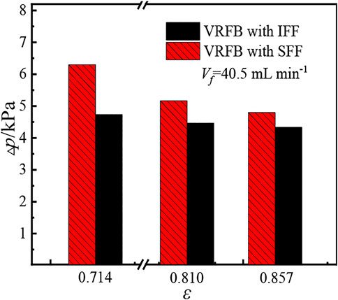
Figure 8. Total pressure drops of batteries with IFF or SFF under various porosities.
According to the analysis of Figures 6, 7, the total pressure drop of the battery with SFF is the sum of the pressure drop of each block, while the total pressure drop of the battery with IFF consists of the pressure drop of the inlet manifold section, the parallel channel section, and the outlet manifold section. Meanwhile, the shunt effect of IFF determines that the pressure drop of the parallel channel section is equal to the pressure drop of a single block in the parallel channel section. Therefore, the pressure drop of the parallel channel section and the total pressure drop of the battery with IFF is limited, which makes the total pressure drop of the battery with IFF lower than that of the battery with SFF. In addition, the shunt effect of IFF leads to a low electrolyte flux in each block of the parallel channel section. Therefore, the pressure drop of the parallel channel section and the total pressure drop of the battery with IFF decreases insignificant as the flow resistance declines. However, the total pressure drop of the battery with SFF significantly decreases with the decrease of the flow resistance. As a result, the divergence in total pressure drop between the two batteries shrinks.
The changes in electrode porosity also affect the electrochemical performance of the batteries with IFF or SFF. Figure 9 shows the total overpotential of the two batteries under various porosities. The total overpotential of both batteries increases with the increment of porosity. The total overpotential consists of activation overpotential, ohmic overpotential, and concentration overpotential. The activation overpotential is considered to remain almost unchanged since the electrode material is unchanged but only deformed. The increase of porosity means the decrease in compression degree of the electrode, which leads to the increase of the bulk resistance of the electrode and the contact resistance between the electrode and bipolar plate. In addition, the increase of porosity also influences the electrolyte distribution, which causes the fluctuation of concentration overpotential (the variation of concentration overpotential is affected by the porosity and thickness of electrode, which is analyzed in section 3.3). The total overpotential has the same variation trend as the ohmic overpotential, which may be attributed to the fact that the increment of ohmic overpotential is larger than the variation of the concentration overpotential, and thereby the variation of total overpotential is dominated by ohmic overpotential.
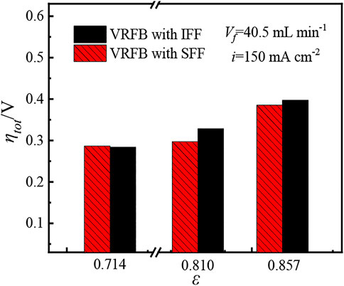
Figure 9. Total overpotentials of the batteries with IFF or SFF.
In addition, at porosity of 0.714, the total overpotential of the battery with IFF is 0.003 V lower than that of the battery with SFF. However, when the porosity increases to 0.810 and 0.857, the total overpotential of the battery with IFF is 0.031 and 0.012 V higher than that of the battery with SFF, respectively. Since the electrodes in the two batteries are the same, it can be considered that the activation overpotential and ohmic overpotential of the two batteries are equal. Hence, the divergence in total overpotential between the two batteries is attributed to their different concentration overpotentials. The analysis of Figures 6, 7 shows that in the battery with IFF, the changes in the electrode permeation resistance do not affect the electrolyte permeation flux into electrode. In addition, though the shunt effect of IFF ensures the uniform distribution of electrolyte in in-plane direction, the shunt effect also leads to a low electrolyte flux in each parallel channel, which results in a weak electrolyte penetration in through-plane direction. For the battery with SFF, the electrolyte flow rate in SFF is much higher than that in IFF, which helps to enhance the electrolyte permeation in both in-plane direction and through-plane direction at a high electrode porosity. However, the electrolyte permeation flux into the electrode in the battery with SFF decreases when the electrode porosity declines. At porosity of 0.714, the excessive low porosity means a high permeation flow resistance, which reduces the permeation flow flux in the battery with SFF but has no influence on the permeation flow flux in the battery with IFF. Therefore, the phenomenon of insufficient electrolyte supply is more likely to occur in the battery with SFF, which leads to a higher concentration overpotential and total overpotential of the battery with SFF than that of the battery with IFF. When the electrode porosity increases to 0.810 and 0.857, the decrease of permeation flow resistance leads to a significant increase of permeation flow flux in the battery with SFF, which helps to suppress the concentration overpotential. Meanwhile, the increase of porosity is accompanied by the increment of electrode thickness, which further magnifies the weakness of IFF on promoting the electrolyte penetration in through-plane direction. As a result, the battery with IFF exhibits higher concentration overpotential and total overpotential than the battery with SFF due to the poorer electrolyte uniformity in through-plane direction. The analysis of Figure 9 indicates that the variation of porosity can cause a reversal of total overpotential between the batteries with IFF and SFF, implying that the change in porosity leads to a performance reversal between IFF and SFF.
The total pressure drop and total overpotential of the batteries with IFF or SFF under various electrode thicknesses are also compared to study the effect of electrode thickness on the performance of flow fields. Figures 10A,B present the total pressure drop of the two batteries with L4 electrodes and L2 electrodes, respectively. The results show that the variation of total pressure drop of the two batteries with L4 electrodes or L2 electrodes is the same as that of the two batteries with L3 electrodes (see Figure 8). That is, the total pressure drop of both batteries decreases with the increase of porosity. Meanwhile, the total pressure drop of the battery with IFF is lower than that of the battery with SFF, and the divergence in total pressure drop between the two batteries decreases with the increase of porosity. In addition, the total pressure drop of the batteries with L4 electrodes is lower than that of the batteries with L2 electrodes. Meanwhile, when using the L4 electrodes, the total pressure drop of the battery with SFF is 1.500, 0.767, and 0.433 kPa higher than that of the battery with IFF at electrode porosity of 0.714, 0.810, and 0.857, respectively. When using the L2 electrodes, the difference in the total pressure drop between the two batteries is 2.100, 1.367, and 0.767 kPa at electrode porosity of 0.714, 0.810, and 0.857, respectively. Obviously, the divergence in total pressure drop between the two batteries with L4 electrodes is smaller than that of the two batteries with L2 electrodes.
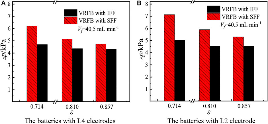
Figure 10. Total pressure drop of the batteries with L4 electrodes or L2 electrodes. (A) Batteries with L4 electrodes. (B) Batteries with L2 electrodes.
The changes of electrode thickness have different effects on the total pressure drop of the batteries with IFF and SFF. Figure 11 is a schematic diagram of electrolyte permeation in batteries with SFF or IFF, which is used to qualitatively illustrate that the variation of electrode thickness has different effects on the total pressure drop of the battery with SFF and the battery with IFF. The red-dashed lines in Figure 11 represent the area in the electrode through which the electrolyte flows. When the number of graphite felts in the electrode is reduced from four (all four layers of graphite felt in Figure 11) to two (two layers of graphite felt above the yellow line in Figure 11), the permeation flow space of the electrolyte decreases, resulting in an increase in the permeation flow resistance. Therefore, under the condition of constant electrolyte input, the total pressure drop of the two batteries with L4 electrodes must be smaller than that of the batteries with L2 electrodes. In addition, according to the analysis of Figures 6, 7, the shunt effect of IFF leads to a low electrolyte flux in each parallel channel and a low electrolyte permeation flux between adjacent parallel channels. Therefore, the electrolyte penetration in through-plane direction in the battery with IFF is weaker than that in the battery with SFF, especially in the case of higher electrode porosity, which is also observed by Gundlapalli and Jayanti (2020) and Messaggi et al. (2018). Obviously, the decrease in permeation flow space has a greater influence on the total pressure drop of the battery with SFF than that of the battery with IFF. As a result, the total pressure drop of the battery with SFF increases faster than that of the battery with IFF when the number of graphite felts in the electrode is reduced from four to two, which causes the divergence in total pressure drop between the two batteries increases with the decrease of electrode thickness. Figures 10, 11 indicate that the reduction in electrode thickness enlarges the divergence in total pressure drop between the batteries with SFF and IFF.
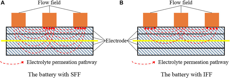
Figure 11. Influence of electrode thickness on the total pressure drop of batteries with IFF or SFF. (A) Battery with SFF. (B) Battery with IFF.
Furthermore, the total overpotential of the two batteries with electrodes of different thicknesses are also investigated. Figure 12A shows the total overpotential of the two batteries with L4 electrodes. With the increase of porosity, the total overpotential of both batteries increases, which is also caused by the increment of ohmic overpotential. In addition, under certain porosity, the total overpotential of the battery with SFF is always lower than that of the battery with IFF. The variation of porosity does not cause the reversal of the total overpotential between the two batteries, which is inconsistent with the results of the batteries with L3 electrodes (see Figure 9). The different results in total overpotential between the batteries with L4 electrodes and the batteries with L3 electrodes may be attributed to two reasons. First, the L4 electrodes provide more reaction sites than the L3 electrodes, and thereby the reaction rate per unit volume of electrode reduces, which is beneficial to alleviate the disadvantage of small permeation flow flux of the battery with SFF at a porosity of 0.714. Second, the ability of IFF to promote the electrolyte penetration along through-plane direction is weaker than that of SFF, and the larger thickness of L4 electrodes further amplifies this deficiency of IFF. Under the combined effect of the two, the total overpotential of the battery with SFF is always lower than that of the battery with IFF.
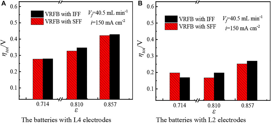
Figure 12. Total overpotentials of the batteries with L4 or L2 electrodes. (A) Batteries with L4 electrodes. (B) Batteries with L2 electrodes.
Figure 12B shows the total overpotential of two batteries with L2 electrodes. As electrode porosity increases, the total overpotential of the battery with IFF increases monotonously while the total overpotential of the battery with SFF first decreases and then increases. Since the activation overpotential remains constant in two batteries and the ohmic overpotential increases monotonically as porosity increases, the different variation in total overpotential of both batteries is attributed to their concentration overpotential. For the battery with IFF, the variation of porosity does not change the permeation flow flux into the electrode, and thereby the influence of porosity on concentration overpotential is weaker than that on ohmic overpotential. The monotonous increase of ohmic overpotential with porosity still dominates the total overpotential. For the battery with SFF, the permeation flow flux increases with the increment of porosity, which contributes to restraining the concentration overpotential. The total overpotential of the battery with SFF first decreases, which means that the decrease in concentration overpotential is greater than the increase in ohmic overpotential when the porosity increases from 0.714 to 0.810; therefore, the variation in total overpotential is dominated by concentration overpotential. With the further increase of porosity, the total overpotential of the battery with SFF increases reversely, which may be because the ohmic overpotential becomes dominant again.
In addition, the total overpotential of the battery with IFF is 0.028 V lower than that of the battery with SFF at porosity of 0.714, and when the porosities are 0.810 and 0.857, the total overpotential of the battery with IFF is 0.030 and 0.017 V higher than that of the battery with SFF, respectively. Obviously, the variation in porosity also causes the performance reversal between SFF and IFF, which is consistent with the phenomenon of the batteries with L3 electrodes (see Figure 9). Moreover, the divergence in total overpotential between the two batteries using L2 electrodes is larger than that of the two batteries using L3 electrodes (see the analysis of Figure 9). The reduction of graphite felt in electrode leads to a surge in the reaction rate per unit volume of the electrode, and thereby the contradiction between electrolyte supply and consumption in batteries with L2 electrodes is intensified. The higher reaction rate per unit volume of the electrode in batteries with L2 electrodes amplifies the shortcoming of insufficient electrolyte supply of the battery with SFF at porosity of 0.714. Meanwhile, the smaller thickness of L2 electrodes shortens the permeation pathway of electrolyte in through-plane direction, which alleviates the weakness of poor ability of IFF on promoting the electrolyte permeation in through-plane direction. Under the combined effect of the two, the total overpotential of the battery with SFF significantly exceeds that of the battery with IFF at porosity of 0.714. When porosities are 0.810 and 0.857, the increased electrode porosity and thickness are more favorable for SFF; as a result, the total overpotential of battery with SFF becomes lower than that with IFF.
The comparisons in total overpotential among the batteries with L2 electrodes (Figure 12B), L3 electrodes (Figure 9), and L4 electrodes (Figure 12A) indicate that the performance reversal between IFF and SFF is pronounced as the electrode thickness decreases, implying that the reduction in electrode thickness helps to promote the performance reversal between IFF and SFF.
The total pressure drop and total overpotential of the batteries with IFF and SFF under different electrolyte inputs and current densities are also analyzed to study the effect of operating conditions on the performance of flow fields. According to the results of Sections 3.2, 3.3, the SFF outperforms IFF when the electrode porosity is higher than 0.810, and a high electrode porosity is more favorable for SFF. Thus, it can be predicted that the performance of SFF is also better than that of IFF at a higher electrode porosity of 0.857. To avoid repetition, only the performances of the batteries using L3−0.810 and L3−0.714 are investigated here.
Figure 13 shows the total pressure drop of the two batteries with L3−0.810 electrode. As the electrolyte input increases, both the permeation flow flux in the electrode and the free-flow flux in channels increase, which causes a monotonical increment in total pressure drop. In addition, the total pressure drop of the battery with SFF is the sum of the pressure drop of each block, and the total pressure drop of the battery with IFF only consists of the pressure drop of the inlet manifold section, the pressure drop of a single block in the parallel channel section, and the pressure drop of the outlet manifold section; hence, the total pressure drop of the battery with SFF is always higher than that of the battery with IFF. Moreover, the shunt effect of IFF determines that the free-flow flux in each parallel channel and the permeation flow flux between adjacent channels is very low; therefore, the increment of electrolyte input has an insignificant effect on the total pressure drop of the battery with IFF. However, the electrolyte flux in SFF is very high, and the increase of electrolyte input causes a great increase in total pressure drop. As a result, when the electrolyte input increases from 27.0 ml min−1 to 67.5 ml min−1, the total pressure drop of the battery with SFF increases from 3.233 to 9.667 kPa, while the total pressure drop of the battery with IFF increases from 2.667 to 8.500 kPa. Obviously, the divergence in total pressure drop between the two batteries enlarges with the increase of electrolyte input. Figure 13 indicates that the increment of electrolyte input enlarges the divergence in pressure drop between the two batteries.
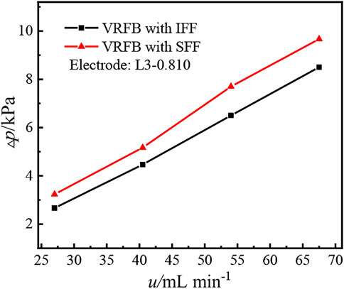
Figure 13. Total pressure drop of two batteries under different electrolyte inputs.
Figure 14 shows the effect of electrolyte input on the total overpotential under different electrode porosities. Figure 14A provides the total overpotential of the two batteries with L3−0.810 electrode. The electrolyte supply is enhanced as the electrolyte input increases, which helps to suppress the concentration overpotential. Hence, the total overpotential of both batteries decreases with the increment of electrolyte input. In addition, for the L3−0.810 electrode, its smaller permeation flow resistance and larger thickness make SFF perform better than IFF on promoting the uniform distribution of the electrolyte (see the analysis of Figure 9); therefore, the total overpotential of the battery with SFF is lower than that of the battery with IFF. In addition, when the electrolyte input increases from 27.0 to 67.5 ml min−1, the total overpotential of the battery with SFF and the battery with IFF decreases by 0.014 and 0.008 V, respectively, indicating that the increment of electrolyte input has a more obvious inhibitory effect on the total overpotential of the battery with SFF, which is attributed that the increase of electrolyte input has different effect on the permeation flow flux in the two batteries. For the battery with IFF, the permeation flow flux is always equal to the electrolyte input; thereby, the growth rate of the permeation flow flux in the battery with IFF is equal to that of the electrolyte input. However, for the battery with SFF, part of electrolyte flows along the channels. When the electrolyte input increases, the growth rate of the pressure drop caused by the free-flow in channels is greater than that of the pressure drop caused by the permeation flow in the electrode, which drives more electrolyte to permeate into the electrode to maintain the balance between the pressure drop caused by free-flow in channels and the pressure drop caused by the permeation flow in the electrode. Hence, the growth rate of permeation flow flux is greater than that of the electrolyte input in the battery with SFF. In other words, the growth rate of permeation flow flux in the battery with SFF is greater than that in the battery with IFF, which leads to a more obvious decline of the total overpotential in the battery with SFF. As a result, the divergence in total overpotential between the two batteries enlarges with the increment of electrolyte input.

Figure 14. Total overpotential of the two batteries under different electrolyte inputs. (A) Batteries with L3−0.810 electrode. (B) Batteries with L3−0.714 electrode.
Figure 14B shows the total overpotential of the two batteries with L3−0.714 electrode. Similarly, since the increased electrolyte input helps to restrain the concentration overpotential, the total overpotential of both batteries decreases as the electrolyte input increases. In addition, the large permeation flow resistance of L3−0.714 electrode inhibits the electrolyte permeation into the electrode in the battery with SFF, resulting in a higher total overpotential of the battery with SFF than that of the battery with IFF at low electrolyte input of 27.0 and 40.5 ml min−1. With the increase of the electrolyte input, since the growth rate of the permeation flow flux in the battery with SFF is higher than that in the battery with IFF, the total overpotential of the battery with SFF declines more obviously. When the electrolyte input exceeds 54.0 ml min−1, the total overpotential of the battery with SFF has become lower than that of the battery with IFF. Figure 14 indicates that the performance reversal between IFF and SFF occurs only at porosity of 0.714, which means that the porosity instead of electrolyte input is the decisive factor for the performance reversal between IFF and SFF. Moreover, the increase of electrolyte input helps to inhibit the performance reversal phenomenon.
Figure 15 investigates the effect of current density on the total overpotential under various electrode porosities. Figure 15A shows the total overpotential of the two batteries with L3−0.810 electrode. As the current density increases, both the ohmic overpotential and activation overpotential increase. Meanwhile, the electrolyte consumption rate increases with the increment of current density. Under the condition of a constant electrolyte input, the contradiction between electrolyte supply and consumption deteriorates, resulting in an increase in the concentration overpotential. Therefore, the total overpotential of both batteries increases with the increment of current density. In addition, the high porosity and the large thickness of L3−0.810 electrode make the SFF show better ability than IFF to promote the permeation and uniform distribution of electrolyte into electrode (see the analysis of Figure 9); therefore, the total overpotential of the battery with SFF is lower than that of the battery with IFF. In addition, the deteriorated contradiction between the electrolyte supply and consumption caused by the increment of current density further amplifies the advantages of the SFF over IFF; as a result, the difference in total overpotential between the two batteries increases from 0.012 to 0.046 V when the current density increases from 75 mA cm−2 to175 mA cm−2, indicating that the divergence in total overpotential between the two batteries enlarges with the increment of current density.
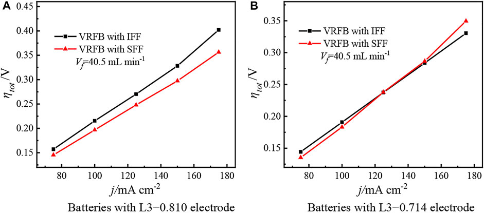
Figure 15. Total overpotential of two batteries at different current densities. (A) Batteries with L3−0.810 electrode. (B) Batteries with L3−0.714 electrode.
Figure 15B shows the total overpotential of the two batteries with L3−0.714 electrode. Similarly, the total overpotential of both batteries increases with the increment of current density. In addition, for L3−0.714 electrode, its low porosity makes the battery with SFF more prone to the problem of insufficient electrolyte supply than the battery with IFF (see the analysis of Figure 9), and the increase in the consumption rate of electrolyte amplifies this disadvantage of the SFF. As a result, the total overpotential of the battery with SFF grows faster than that of the battery with IFF, and the total overpotential of the battery with SFF gradually exceeds than that of the battery with IFF as the current density increases. Figure 15 confirms that the current density is also not the decisive factor for the performance reversal between IFF and SFF. However, the increment of current density promotes the performance reversal phenomenon at low electrode porosity.
Based on the aforementioned analysis, Figure 16 summarizes the effect of electrode parameters and operating conditions on the performance of IFF and SFF, that is, the electrode porosity is the key factor to determine the performance of flow fields. When the electrode porosity is greater than 0.810, SFF can promote the penetration and uniform distribution of electrolyte into the electrode better than IFF; therefore, the discharging performance of the battery with SFF could be better than that of the battery with IFF. As the electrode porosity drops below 0.810, the ability of IFF to promote the penetration and uniform distribution of the electrolyte may be stronger than that of SFF, resulting in a better discharging performance of the battery with IFF. Moreover, the reduction of electrode thickness, the increase of current density, and the reduction of electrolyte input can promote the performance reversal between IFF and SFF.

Figure 16. Effect of electrode parameters and operating conditions on the performance of flow fields.
The aforementioned summary also provides a reasonable explanation for the debate on the superiority of IFF and SFF in previous works. When using the graphite felt as an electrode, Kumar and Jayanti (2016) found that the voltage efficiency of the battery with SFF was higher than that of the battery with IFF, and Maurya et al. (2018) also obtained the results that the power density of the battery with SFF was higher than that of the battery with IFF. Both results indicated that the performance of SFF was better than that of IFF. However, when using the carbon paper as electrode, Houser et al. (2016), Houser et al. (2017), and Tsushima et al. (2013) found that the discharging performance of the battery with IFF was better than that of the battery with SFF, which meant that the performance of IFF was better than SFF. Both the graphite felt and carbon paper are commonly used electrode materials in flow batteries. In addition to the difference in thickness, there are also obvious differences in porosity: the porosity of carbon paper is much lower than that of graphite felt. Taking the commonly used carbon paper electrodes (10AA, 25AA, and 39AA, SGL, Germany) and graphite felt electrodes (GFA series, SGL, Germany) as examples, the initial porosity of carbon paper and graphite felt is about 0.88 and 0.95, respectively. When the two electrodes are properly compressed (the compression ratio is about 40%), the porosity of carbon paper and graphite felt drops to 0.80 and 0.91, respectively. According to the summary of this work, the battery with SFF could provide better discharging performance when using the high porosity graphite felt as an electrode, which is consistent with the results obtained by Kumar and Jayanti (2016) and Maurya et al. (2018). However, when the carbon paper with low porosity is used as an electrode, the discharging performance of the battery with IFF may be better than that of the battery with SFF, which is consistent with the results found by Houser et al. (2016), Houser et al. (2017), and Tsushima et al. (2013). Obviously, the results of this work can well explain the debate on the superiority of IFF and SFF in literatures.
In addition, the summary on the effects of electrode thickness, electrolyte input, and current density on the performance of flow fields are also consistent with the results in literatures. Houser et al. (2016), Houser et al. (2017) found that when the electrolyte input was 90 ml min−1, the battery with IFF and the battery with SFF showed higher discharging potential than each other at current densities of 500 and 250 mA cm−2, respectively. As the electrolyte input decreased to 20 ml min−1, the discharging potential of the battery with IFF was always higher than that of the battery with SFF, and the divergence in discharging potential between the two batteries enlarged as the current density increased from 250 to 500 mA cm−2. These results indicate that IFF performs better than SFF when the current density increases and the electrolyte input decreases, which is consistent with the summary of this work. Furthermore, Houser et al. (2016) also compared the discharging performance of the battery with IFF and the battery with SFF under different electrode thicknesses. The results found that when the electrode was composed of five layers of carbon paper, the discharging potential of the battery with IFF was even lower than that of the battery with SFF. However, the discharging potential of the battery with IFF was always higher than that of the battery with SFF when the electrode was composed of three or one layer of carbon paper, and the divergence in discharging potential between the two batteries widened with the decrease of carbon paper in the electrode. Obviously, this variation trend is consistent with the summary of this work that the reduction of electrode thickness enhances the performance reversal between IFF and SFF at low electrode porosity, which is also consistent with the opinion of Macdonald and Darling (2019) that “SFF preferred thick electrodes and high flow rates in comparison with IFF.” The aforementioned analyses confirm that the conclusions of this work achieve the unification of the results in literatures.
The performance of flow fields is closely related to the electrode parameters. In this work, under various electrolyte inputs and current densities, the effect of electrode parameters including the porosity and thickness on the performance of SFF and IFF are experimentally investigated. The results indicate that the shunt effect of IFF makes the total pressure drop of the battery with IFF smaller than that with SFF. The divergence in total pressure drop between the two batteries enlarges with the decrease of electrode porosity, the increase of electrolyte input, and decrease of electrode thickness. The influence of flow fields on the electrochemical behavior of VRFBs depends on the electrode porosity. When electrode porosity is greater than 0.810, the SFF exhibits a better performance than IFF on enhancing the uniform distribution of electrolyte. However, as electrode porosity decreases to 0.714, the performance of IFF may outperform SFF, resulting in a lower total overpotential in the battery with IFF. In addition, the changes in electrode thickness and operating conditions also influence the performance reversal between IFF and SFF at low electrode porosity. The increase in current density, the decrease in electrolyte input, and the decrease in electrode thickness can enhance the advantages of IFF over SFF in enhancing the uniform distribution of electrolyte at low electrode porosity. The results obtained in this work well explain the debate on the superiority of IFF and SFF as well as the discussion on the preference between flow fields and electrode thickness in literatures; meanwhile, the results also provide guidance for the selection of the types of flow fields in VRFBs.
The original contributions presented in the study are included in the article/Supplementary Material; further inquiries can be directed to the corresponding author.
ZD: conceptualization, methodology, investigation, and writing—original draft; GZ: writing—review and editing; JZ: writing—review and editing; and ZQ: supervision, resources, writing—review and editing.
This work was supported by the Foundation for Innovative Research Groups of the National Natural Science Foundation of China (No. 51721004).
The authors declare that the research was conducted in the absence of any commercial or financial relationships that could be construed as a potential conflict of interest.
All claims expressed in this article are solely those of the authors and do not necessarily represent those of their affiliated organizations, or those of the publisher, the editors, and the reviewers. Any product that may be evaluated in this article, or claim that may be made by its manufacturer, is not guaranteed or endorsed by the publisher.
Aaron, D., Tang, Z., Papandrew, A. B., and Zawodzinski, T. A. (2011). Polarization Curve Analysis of All-Vanadium Redox Flow Batteries. J. Appl. Electrochem 41 (10), 1175–1182. doi:10.1007/s10800-011-0335-7
Amirante, R., Cassone, E., Distaso, E., and Tamburrano, P. (2017). Overview on Recent Developments in Energy Storage: Mechanical, Electrochemical and Hydrogen Technologies. Energy Convers. Manag. 132, 372–387. doi:10.1016/j.enconman.2016.11.046
Arenas, L. F., Ponce de León, C., and Walsh, F. C. (2017). Engineering Aspects of the Design, Construction and Performance of Modular Redox Flow Batteries for Energy Storage. J. Energy Storage 11, 119–153. doi:10.1016/j.est.2017.02.007
Becker, M., Bredemeyer, N., Tenhumberg, N., and Turek, T. (2016). Polarization Curve Measurements Combined with Potential Probe Sensing for Determining Current Density Distribution in Vanadium Redox-Flow Batteries. J. Power Sources 307, 826–833. doi:10.1016/j.jpowsour.2016.01.011
Bromberger, K., Kaunert, J., and Smolinka, T. (2014). A Model for All-Vanadium Redox Flow Batteries: Introducing Electrode-Compression Effects on Voltage Losses and Hydraulics. Energy Technol. 2 (1), 64–76. doi:10.1002/ente.201300114
Chi, P. H., Chan, S. H., Weng, F. B., Su, A., Sui, P. C., and Djilali, N. (2010). On the Effects of Non-uniform Property Distribution Due to Compression in the Gas Diffusion Layer of a PEMFC. Int. J. Hydrogen Energy 35 (7), 2936–2948. doi:10.1016/j.ijhydene.2009.05.066
Duan, Z., Qu, Z., Ren, Q., and Zhang, J. (2021). Review of Bipolar Plate in Redox Flow Batteries: Materials, Structures, and Manufacturing. Electrochem. Energy Rev. 4 (4), 718–756. doi:10.1007/s41918-021-00108-4
Fetyan, A., El-Nagar, G. A., Derr, I., Kubella, P., Dau, H., and Roth, C. (2018). A Neodymium Oxide Nanoparticle-Doped Carbon Felt as Promising Electrode for Vanadium Redox Flow Batteries. Electrochimica Acta 268, 59–65. doi:10.1016/j.electacta.2018.02.104
Ghimire, P. C., Bhattarai, A., Schweiss, R., Scherer, G. G., Wai, N., and Yan, Q. (2018). A Comprehensive Study of Electrode Compression Effects in All Vanadium Redox Flow Batteries Including Locally Resolved Measurements. Appl. Energy 230, 974–982. doi:10.1016/j.apenergy.2018.09.049
Gundlapalli, R., and Jayanti, S. (2020). Performance Characteristics of Several Variants of Interdigitated Flow Fields for Flow Battery Applications. J. Power Sources 467, 228225. doi:10.1016/j.jpowsour.2020.228225
Houser, J., Clement, J., Pezeshki, A., and Mench, M. M. (2016). Influence of Architecture and Material Properties on Vanadium Redox Flow Battery Performance. J. Power Sources 302, 369–377. doi:10.1016/j.jpowsour.2015.09.095
Houser, J., Pezeshki, A., Clement, J. T., Aaron, D., and Mench, M. M. (2017). Architecture for Improved Mass Transport and System Performance in Redox Flow Batteries. J. Power Sources 351, 96–105. doi:10.1016/j.jpowsour.2017.03.083
Jyothi Latha, T., and Jayanti, S. (2014). Hydrodynamic Analysis of Flow Fields for Redox Flow Battery Applications. J. Appl. Electrochem 44 (9), 995–1006. doi:10.1007/s10800-014-0720-0
Ke, X., Prahl, J. M., Alexander, J. I. D., and Savinell, R. F. (2018). Redox Flow Batteries with Serpentine Flow Fields: Distributions of Electrolyte Flow Reactant Penetration into the Porous Carbon Electrodes and Effects on Performance. J. Power Sources 384, 295–302. doi:10.1016/j.jpowsour.2018.03.001
Kim, K. J., Lee, S.-W., Yim, T., Kim, J.-G., Choi, J. W., Kim, J. H., et al. (2014). A New Strategy for Integrating Abundant Oxygen Functional Groups into Carbon Felt Electrode for Vanadium Redox Flow Batteries. Sci. Rep. 4, 6906. doi:10.1038/srep06906
Kumar, S., and Jayanti, S. (2016). Effect of Flow Field on the Performance of an All-Vanadium Redox Flow Battery. J. Power Sources 307, 782–787. doi:10.1016/j.jpowsour.2016.01.048
Li, S., Huang, K., Liu, S., Fang, D., Wu, X., Lu, D., et al. (2011). Effect of Organic Additives on Positive Electrolyte for Vanadium Redox Battery. Electrochimica Acta 56 (16), 5483–5487. doi:10.1016/j.electacta.2011.03.048
Macdonald, M., and Darling, R. M. (2019). Comparing Velocities and Pressures in Redox Flow Batteries with Interdigitated and Serpentine Channels. AIChE J. 65 (5), e16553. doi:10.1002/aic.16553
Maurya, S., Nguyen, P. T., Kim, Y. S., Kang, Q., and Mukundan, R. (2018). Effect of Flow Field Geometry on Operating Current Density, Capacity and Performance of Vanadium Redox Flow Battery. J. Power Sources 404, 20–27. doi:10.1016/j.jpowsour.2018.09.093
Messaggi, M., Canzi, P., Mereu, R., Baricci, A., Inzoli, F., Casalegno, A., et al. (2018). Analysis of Flow Field Design on Vanadium Redox Flow Battery Performance: Development of 3D Computational Fluid Dynamic Model and Experimental Validation. Appl. Energy 228, 1057–1070. doi:10.1016/j.apenergy.2018.06.148
Messaggi, M., Rabissi, C., Gambaro, C., Meda, L., Casalegno, A., and Zago, M. (2020). Investigation of Vanadium Redox Flow Batteries Performance through Locally-Resolved Polarisation Curves and Impedance Spectroscopy: Insight into the Effects of Electrolyte, Flow Field Geometry and Electrode Thickness. J. Power Sources 449, 227588. doi:10.1016/j.jpowsour.2019.227588
Minke, C., and Turek, T. (2015). Economics of Vanadium Redox Flow Battery Membranes. J. Power Sources 286, 247–257. doi:10.1016/j.jpowsour.2015.03.144
Pezeshki, A. M., Sacci, R. L., Delnick, F. M., Aaron, D. S., and Mench, M. M. (2017). Elucidating Effects of Cell Architecture, Electrode Material, and Solution Composition on Overpotentials in Redox Flow Batteries. Electrochimica Acta 229, 261–270. doi:10.1016/j.electacta.2017.01.056
Reed, D., Thomsen, E., Li, B., Wang, W., Nie, Z., Koeppel, B., et al. (2016). Performance of a Low Cost Interdigitated Flow Design on a 1 kW Class All Vanadium Mixed Acid Redox Flow Battery. J. Power Sources 306, 24–31. doi:10.1016/j.jpowsour.2015.11.089
Skyllas-Kazacos, M., Chakrabarti, M. H., Hajimolana, S. A., Mjalli, F. S., and Saleem, M. (2011). Progress in Flow Battery Research and Development. J. Electrochem. Soc. 158 (8), R55–R79. doi:10.1149/1.3599565
Tariq, F., Rubio-Garcia, J., Yufit, V., Bertei, A., Chakrabarti, B. K., Kucernak, A., et al. (2018). Uncovering the Mechanisms of Electrolyte Permeation in Porous Electrodes for Redox Flow Batteries through Real Timein situ3D Imaging. Sustain. Energy Fuels 2 (9), 2068–2080. doi:10.1039/C8SE00174J
Tsushima, S., Sasaki, S., and Hirai, S. (2013). “Influence of Cell Geometry and Operating Parameters on Performance of a Redox Flow Battery with Serpentine and Interdigitated Flow Fields,” in The Electrochemical Society Meeting, San Francisco, CA, October 27–November 1, 2013, 1664.
Wang, Q., Qu, Z. G., Jiang, Z. Y., and Yang, W. W. (2018). Experimental Study on the Performance of a Vanadium Redox Flow Battery with Non-uniformly Compressed Carbon Felt Electrode. Appl. Energy 213, 293–305. doi:10.1016/j.apenergy.2018.01.047
Wu, L., Shen, Y., Yu, L., Xi, J., and Qiu, X. (2016). Boosting Vanadium Flow Battery Performance by Nitrogen-Doped Carbon Nanospheres Electrocatalyst. Nano Energy 28, 19–28. doi:10.1016/j.nanoen.2016.08.025
Xiang, Y., and Daoud, W. A. (2019). Binary NiCoO2-Modified Graphite Felt as an Advanced Positive Electrode for Vanadium Redox Flow Batteries. J. Mat. Chem. A 7 (10), 5589–5600. doi:10.1039/c8ta09650c
Yang, Z., Zhang, J., Kintner-Meyer, M. C. W., Lu, X., Choi, D., Lemmon, J. P., et al. (2011). Electrochemical Energy Storage for Green Grid. Chem. Rev. 111 (5), 3577–3613. doi:10.1021/cr100290v
Keywords: all-vanadium redox flow battery, flow field, electrode parameter, performance reversal, experiment
Citation: Duan ZN, Zhang GB, Zhang JF and Qu ZG (2022) Experimental Investigation on the Performance Characteristics of Flow Fields in Redox Flow Batteries Under Various Electrode Parameters. Front. Therm. Eng. 2:931160. doi: 10.3389/fther.2022.931160
Received: 28 April 2022; Accepted: 13 June 2022;
Published: 05 August 2022.
Edited by:
Haifeng Liu, Tianjin University, ChinaReviewed by:
Dongliang Sun, Beijing Institute of Petrochemical Technology, ChinaCopyright © 2022 Duan, Zhang, Zhang and Qu. This is an open-access article distributed under the terms of the Creative Commons Attribution License (CC BY). The use, distribution or reproduction in other forums is permitted, provided the original author(s) and the copyright owner(s) are credited and that the original publication in this journal is cited, in accordance with accepted academic practice. No use, distribution or reproduction is permitted which does not comply with these terms.
*Correspondence: Z. G. Qu, emdxdUBtYWlsLnhqdHUuZWR1LmNu
Disclaimer: All claims expressed in this article are solely those of the authors and do not necessarily represent those of their affiliated organizations, or those of the publisher, the editors and the reviewers. Any product that may be evaluated in this article or claim that may be made by its manufacturer is not guaranteed or endorsed by the publisher.
Research integrity at Frontiers
Learn more about the work of our research integrity team to safeguard the quality of each article we publish.